ESP32-S3-DualEye-Touch-LCD-1.28

ESP32-S3-DualEye-Touch-LCD-1.28 is a microcontroller development board that supports 2.4GHz Wi-Fi and BT BLE 5. It integrates large capacity Flash and PSRAM, featuring two 1.28inch LCD on board, capable of smoothly running GUI interface programs such as LVGL. Combined with various peripheral interfaces, it is suitable for the quick development of the HMI and other ESP32-S3 applications.
| SKU | Product |
|---|---|
| 32265 | ESP32-S3-DualEye-Touch-LCD-1.28 |
Features
- Powered by the ESP32-S3R8 high-performance Xtensa 32-bit LX7 dual-core processor, with a main frequency of up to 240 MHz
- Supports 2.4 GHz Wi‑Fi (802.11 b/g/n) and Bluetooth 5 (LE) with an onboard antenna
- Built-in 512 KB SRAM and 384 KB ROM, with 8 MB PSRAM stacked and onboard 16 MB Flash (supports connecting external expansion devices)
- Type-C interface for improved user convenience and device compatibility
- Onboard two 1.28inch LCD screens, resolution 240 × 240, 65K colors
- Supports I2C interface for touch control, with interrupt support
- Exposes UART, I2C, and some I/O interfaces
- Onboard 3.7V MX1.25 lithium battery charge/discharge interface
- Onboard TF card slot for expanded storage and fast data transfer, offering flexibility for data logging and media playback, simplifying circuit design
- Supports precise control of flexible clock and multiple power modes for low-power applications across various scenarios
- Multiple GPIOs brought out, can be mapped to various function interfaces for customized development
Onboard Resources
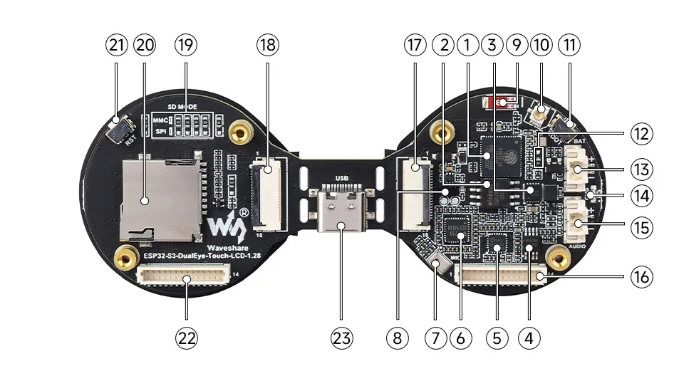
- ESP32-S3R8 Dual-core processor, operating frequency up to 240MHz
- 16MB Flash
- Battery charging management chip
- Power amplifier chip
- ES8311 Low-power audio codec chip
- ES7210
- Microphone
- MP1605GTF-Z Power module, supporting up to 3.3V 2A output
- Onboard ceramic antenna
- IPEX1 connector Switching to use the external antenna via resoldering an onboard resistor
- BOOT button
- GPIO1 function modification resistor Default soldered near the crystal, GPIO1 is used for battery voltage measurement. If changed to the position away from the crystal, the signal is routed to the FPC cable, allowing software modification for triple-screen display
- Battery header MX1.25 2PIN connector for 3.7V lithium battery, supports charging and discharging
- Charging indicator When a system battery is connected, it stays on while charging and turns off when fully charged (status indeterminate when no system battery is connected)
- Speaker header
- LCD1-Board SH1.0 14PIN header For programming and log printing
- 18PIN FPC connector While the main board is powered on, adjust the resistor value at position R12 and modify the display configuration parameters in the software to achieve triple-screen display. If the board is broken off, the FPC cable can connect both screens to work properly (note: the RESET button is not available when the board is broken off and connected via FPC cable)
- 18PIN FPC header For connecting the main controller
- TF card communication mode selection When the board is broken off, the side controlling the TF card can be switched to SPI mode, allowing one SPI to control both the TF card and the screen simultaneously
- TF card slot Allows connection of high-capacity TF cards
- RESET button
- LCD2-Board SH1.0 14PIN cable header When the board is broken off, configure the resistor at position R19 for SPI mode, then the 14PIN FPC can be used to control both the TF card and the screen via one SPI bus
- Type-C port
Interface Introduction
| Pin No. | LCD1-Board SH1.0 14PIN FPC cable header | LCD2-Board SH1.0 14PIN FPC cable header |
|---|---|---|
| 1 | USB_5V | 3V3 |
| 2 | GND | GND |
| 3 | D_N | SD_MISO |
| 4 | D_P | SD_MOSI |
| 5 | 3V3 | SD_SCLK |
| 6 | GND | SD_CS |
| 7 | SDA | LCD_CS2' |
| 8 | SCL | LCD_DC |
| 9 | UART_RXD | LCD_RST2 |
| 10 | UART_TXD | LCD_BL2 |
| 11 | TP2_SDA | TP2_SDA |
| 12 | TP2_SCL | TP2_SCL |
| 13 | GPIO0 | TP2_INT |
| 14 | RESET | TP2_RST |
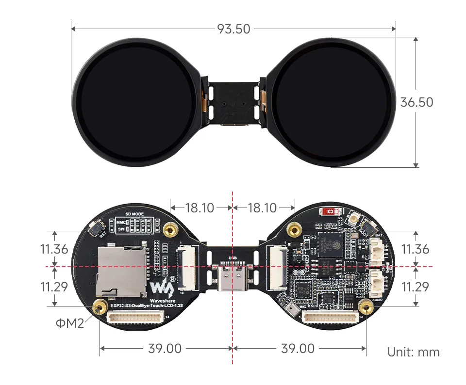
Dimensions
Development Methods
The ESP32-S3-DualEye-Touch-LCD-1.28 supports two development frameworks: Arduino IDE and ESP-IDF, offering flexibility for developers. You can choose the appropriate development tool based on project requirements and personal preferences.
Both development methods have their own advantages. Developers can choose based on their needs and skill levels. Arduino is simple to learn and quick to start, suitable for beginners and non-professionals. ESP-IDF provides more advanced development tools and stronger control capabilities, suitable for developers with professional backgrounds or higher performance requirements, and is more appropriate for complex project development.
-
Arduino IDE is a convenient, flexible, and easy-to-use open-source electronics prototyping platform. It requires minimal foundational knowledge, allowing for rapid development after a short learning period. Arduino has a huge global user community, providing a vast amount of open-source code, project examples, and tutorials, as well as a rich library ecosystem that encapsulates complex functions, enabling developers to implement various features rapidly. You can refer to the Working with Arduino to complete the initial setup, and the tutorial also provides related example programs for reference.
-
ESP-IDF, short for Espressif IoT Development Framework, is a professional development framework launched by Espressif Systems for its ESP series of chips. It is based on C language development and includes compilers, debuggers, flashing tools, etc. It supports development via command line or integrated development environments (such as Visual Studio Code with the Espressif IDF plugin), which provides features like code navigation, project management, and debugging. We recommend using VS Code for development. For the specific configuration process, please refer to the Working with ESP-IDF. The tutorial also provides relevant example programs for reference.