ESP32-S3-LCD-2.8
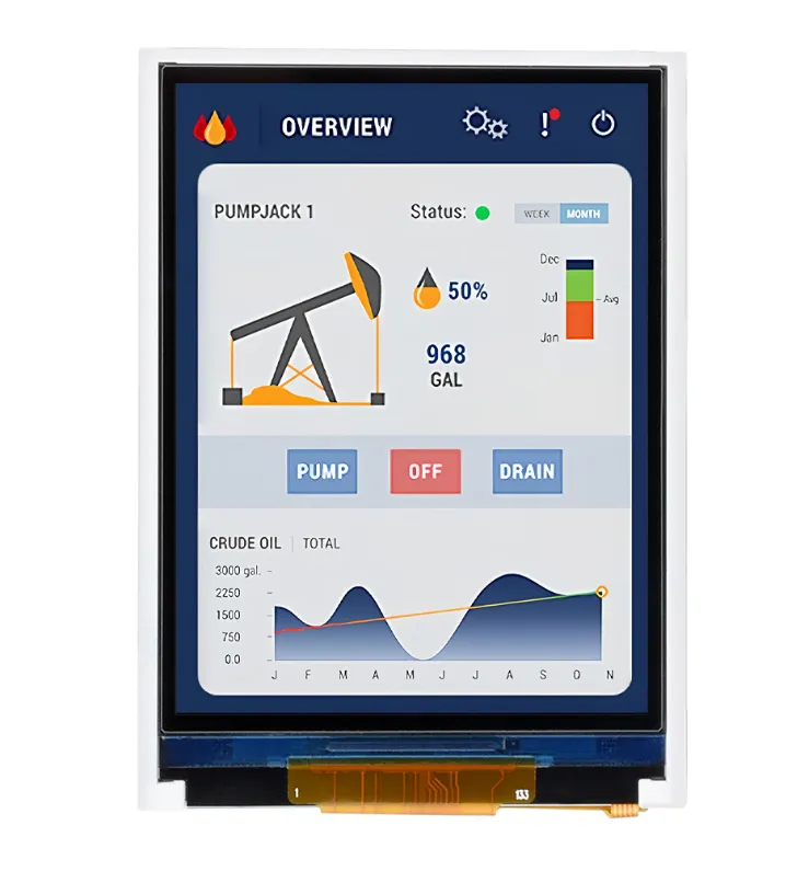
ESP32-S3-LCD-2.8 is a microcontroller development board that supports 2.4GHz Wi-Fi and BLE 5. It integrates large capacity Flash and PSRAM and has onboard 2.8inch capacitive touch screen, can smoothly run GUI programs such as LVGL. Combined with various peripheral interfaces, it is suitable for the quick development of the HMI and other ESP32-S3 applications.
| SKU | Product |
|---|---|
| 27690 | ESP32-S3-Touch-LCD-2.8 |
| 30223 | ESP32-S3-LCD-2.8 |
Features
- Powered by a high-performance Xtensa 32-bit LX7 dual-core processor, with a main frequency of up to 240MHz
- Supports 2.4 GHz Wi-Fi (802.11 b/g/n) and Bluetooth 5 (LE) with an onboard antenna
- Onboard 512 KB SRAM and 384 KB ROM, with stacked 16 MB Flash and 8 MB PSRAM
- Onboard 2.8inch capacitive touch screen, 240 × 320 resolution, 262K colors
- Supports I2C interface control for capacitive touch, with 5-point touch, and supports interrupts
- Exposes UART, I2C, and some I/O interfaces; integrated full‑speed USB serial port
- Onboard speaker, QMI8658 6‑axis IMU, RTC clock sensor, TF card slot, and battery charging management module
- Supports flexible clock control and various power modes for low-power scenarios
Onboard Resources
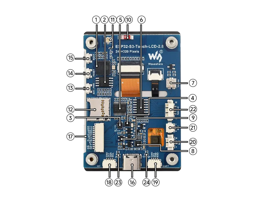
- ESP32-S3R8 Dual-core processor, operating frequency up to 240MHz
- 16MB Flash
- QST Attitude Sensor QMI8658 (6‑axis gyroscope + accelerometer)
- RTC Chip PCF85063 RTC clock
- PCM5101 Audio Decoder Chip
- Amplifier Chip
- Volume Adjustment Knob
- Battery Charging Management Chip
- ME6217C33M5G Low dropout LDO, current (Max) 800mA
- Onboard Ceramic Antenna
- IPEX1 Connector and Switch Resistor Switching to use the external antenna via resoldering the resistor
- TF card slot
- Battery Power Control Button Relevant driver program is required
- RESET Button
- BOOT Button
- USB Type-C Interface For programming and log output
- 12PIN Multi‑function Interface
- I2C Header Connected to other onboard chips; only for connecting external I2C devices, cannot be remapped to other functions
- UART Header
- Battery Header MX1.25 2PIN connector for 3.7V lithium battery, supports charging and discharging
- RTC Battery Header For connecting a rechargeable RTC battery
- Speaker Header Comes with 8Ω 2W 2030 speaker
- Power Indicator
- Charging Indicator When a system battery is connected, it stays on while charging and turns off when fully charged (status indeterminate when no system battery is connected)
Interface Description
When using the ESP32-S3-LCD-2.8, it is important to understand the following interface descriptions.
12PIN Wire Interface Pin Mapping Table (click to expand)
| Pin Marking | Function | Description |
|---|---|---|
| GND | GND | Power ground |
| VBus | 5V | USB power |
| D- | USB differential (GPIO19) | USB differential or GPIO |
| D+ | USB differential (GPIO20) | USB differential or GPIO |
| GND | GND | Power ground |
| 3V3 | 3V3 | 3.3V output |
| SCL | SCL (GPIO10) | I2C clock line, cannot be used as a regular GPIO |
| SDA | SDA (GPIO11) | I2C data line, cannot be used as a regular GPIO |
| TXD | TXD (GPIO43) | UART data transmit or can be used as a regular GPIO |
| RXD | RXD (GPIO44) | UART data receive or can be used as a regular GPIO |
| IO18 | GPIO18 | Spare GPIO pin |
| IO15 | GPIO15 | Spare GPIO pin |
I2C Interface Pin Mapping Table (click to expand)
| Pin Marking | Function | Description |
|---|---|---|
| GND | GND | Power ground |
| 3V3 | 3V3 | 3.3V output |
| SCL | SCL (GPIO10) | I2C clock line, cannot be used as a regular GPIO |
| SDA | SDA (GPIO11) | I2C data line, cannot be used as a regular GPIO |
UART Interface Pin Mapping Table (click to expand)
| Pin Marking | Function | Description |
|---|---|---|
| GND | GND | Power ground |
| 3V3 | 3V3 | 3.3V output |
| TXD | TXD (GPIO43) | UART data transmit or can be used as a regular GPIO |
| RXD | RXD (GPIO44) | UART data receive or can be used as a regular GPIO |
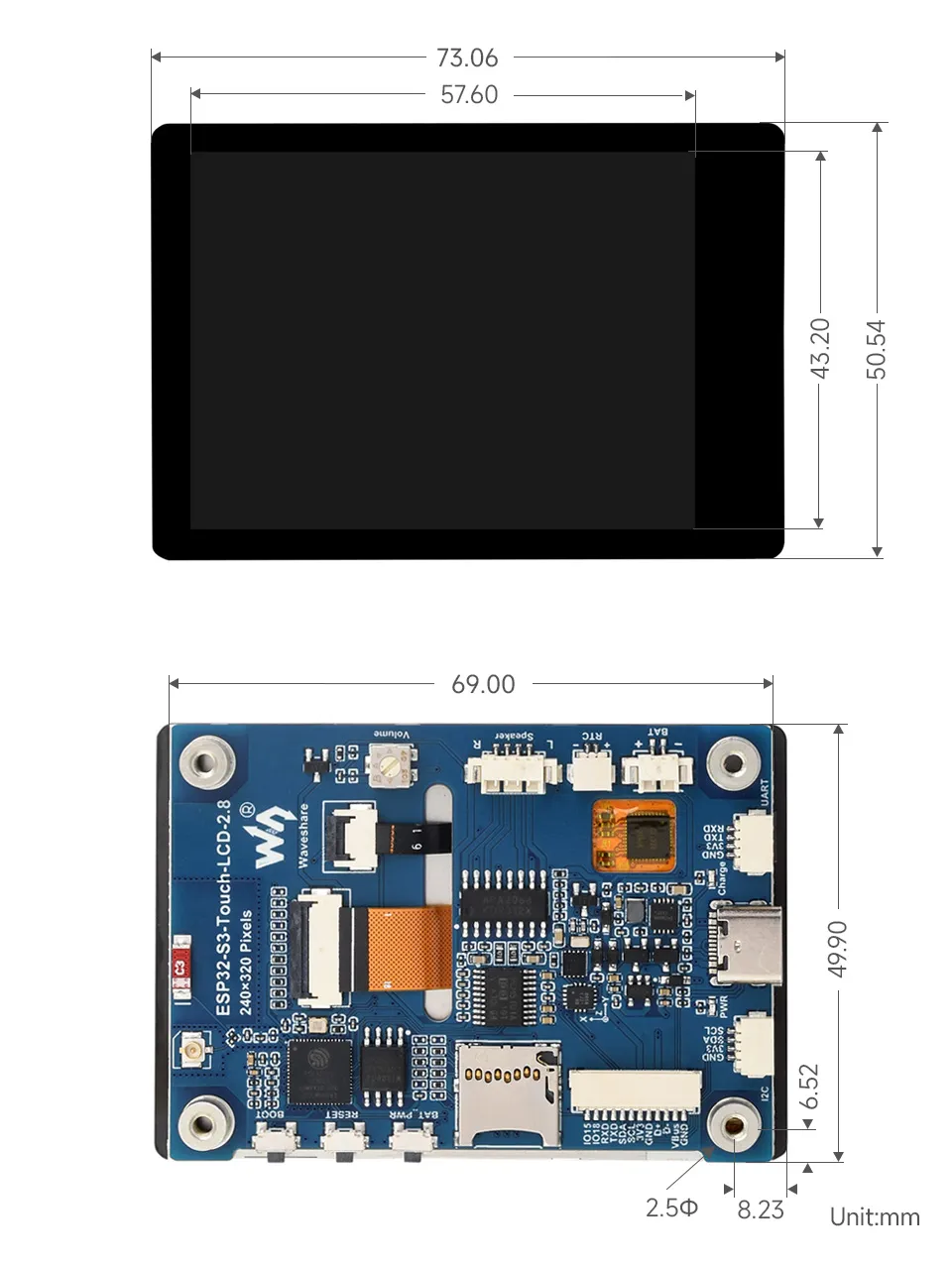
Dimensions
Development Methods
The ESP32-S3-LCD-2.8 supports two development frameworks: Arduino IDE and ESP-IDF, offering flexibility for developers. You can choose the appropriate development tool based on project requirements and personal preferences.
Both development methods have their own advantages. Developers can choose based on their needs and skill levels. Arduino is simple to learn and quick to start, suitable for beginners and non-professionals. ESP-IDF provides more advanced development tools and stronger control capabilities, suitable for developers with professional backgrounds or higher performance requirements, and is more appropriate for complex project development.
-
Arduino IDE is a convenient, flexible, and easy-to-use open-source electronics prototyping platform. It requires minimal foundational knowledge, allowing for rapid development after a short learning period. Arduino has a huge global user community, providing a vast amount of open-source code, project examples, and tutorials, as well as a rich library ecosystem that encapsulates complex functions, enabling developers to implement various features rapidly. You can refer to the Working with Arduino to complete the initial setup, and the tutorial also provides related demos for reference.
-
ESP-IDF, short for Espressif IoT Development Framework, is a professional development framework launched by Espressif Systems for its ESP series of chips. It is based on C language development and includes compilers, debuggers, flashing tools, etc. It supports development via command line or integrated development environments (such as Visual Studio Code with the Espressif IDF plugin), which provides features like code navigation, project management, and debugging. We recommend using VS Code for development. For the specific configuration process, please refer to the Working with ESP-IDF. The tutorial also provides relevant demos for reference.