ESP-IDF
This chapter contains the following sections. Please read as needed:
ESP-IDF Getting Started
New to ESP32 ESP-IDF development and looking to get started quickly? We have prepared a general Getting Started Tutorial for you.
- Section 1: Environment Setup
- Section 2: Running Examples
- Section 3: Creating a Project
- Section 4: Using Components
- Section 5: Debugging
- Section 6: FreeRTOS
- Section 7: Peripherals
- Section 8: Wi-Fi Programming
- Section 9: BLE Programming
Please Note: This tutorial uses the ESP32-S3-Zero as a teaching example, and all hardware code is based on its pinout. Before you start, it is recommended that you check the pinout of your development board to ensure the pin configuration is correct.
Setting Up Development Environment
The following guide uses Windows as an example, demonstrating development using VS Code + the ESP-IDF extension. macOS and Linux users should refer to the official documentation.
The screenshots in this section use ESP-IDF V5.5.2 as an example. When installing, please select the ESP-IDF version that matches your board's example.
Install the ESP-IDF Development Environment
-
Download the installation manager from the ESP-IDF Installation Manager page. This is Espressif's latest cross-platform installer. The following steps demonstrate how to use its offline installation feature.
Click the Offline Installer tab on the page, then select Windows as the operating system and the ESP-IDF version you need (the version shown in the screenshot is for reference only — choose the version that fits your actual needs).

After confirming your selection, click the download button. The browser will automatically download two files: the ESP-IDF Offline Package (.zst) and the ESP-IDF Installer (.exe).

Please wait for both files to finish downloading.
-
Once the download is complete, double-click to run the ESP-IDF Installer (eim-gui-windows-x64.exe).
The installer will automatically detect if the offline package exists in the same directory. Click Install from archive.

Next, select the installation path. We recommend using the default path. If you need to customize it, ensure the path does not contain Chinese characters or spaces. Click Start installation to proceed.

-
When you see the following screen, the ESP-IDF installation is successful.

-
We recommend installing the drivers as well. Click Finish installation, then select Install driver.

Install Visual Studio Code and the ESP-IDF Extension
-
Download and install Visual Studio Code.
-
During installation, it is recommended to check Add "Open with Code" action to Windows Explorer file context menu to facilitate opening project folders quickly.
-
In VS Code, click the Extensions icon
 in the Activity Bar on the side (or use the shortcut Ctrl + Shift + X) to open the Extensions view.
 -
Enter ESP-IDF in the search box, locate the ESP-IDF extension, and click Install.

-
For ESP-IDF extension versions ≥ 2.0, the extension will automatically detect and recognize the ESP-IDF environment installed in the previous steps, requiring no manual configuration.
Demo
The ESP-IDF demos are located in the ESP-IDF directory of the demo package.
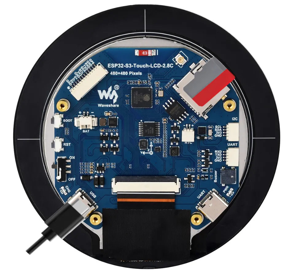
ESP32-S3-LCD-2.8C-Test
Demo Description
- This example demonstrates how to integrate the LVGL graphics library on an embedded device. By coordinating hardware initialization and graphics library initialization, a complete graphical interface runtime environment is built. Continuously calling the LVGL core loop ensures that the graphical interface responds to user interactions and refreshes system status in real time while properly managing CPU resource usage.
Hardware Connection
- Insert the TF card into the development board
- Connect the development board to the computer
Code Analysis
-
Driver_Init():- This function initializes the hardware and creates a task. It initializes the flash memory, the battery, the I2C bus, the real-time clock, the gyroscope, and external IO. It then creates a task
Driver_Loopthat continuously processes the gyroscope, real-time clock, and battery voltage, performing loop operations every 100 milliseconds.
- This function initializes the hardware and creates a task. It initializes the flash memory, the battery, the I2C bus, the real-time clock, the gyroscope, and external IO. It then creates a task
-
Driver_Loop():- Runs as a continuous task, repeatedly processing gyroscope and real-time clock operations and obtaining battery voltage. This ensures that the status of these hardware devices is continuously updated.
-
app_main():- This is the main entry function of the program. It first initializes the wireless module, then calls
Driver_Initfor hardware initialization. Next, initialize the LCD display, TF card, LVGL graphics library and analog touch input in sequence. Next, it initializes the LCD display, TF card, LVGL graphics library, and simulates touch input. In the main loop, it delays for 10 milliseconds and callslv_timer_handlerto process LVGL timer events, ensuring proper operation and updating of the graphical interface.
- This is the main entry function of the program. It first initializes the wireless module, then calls
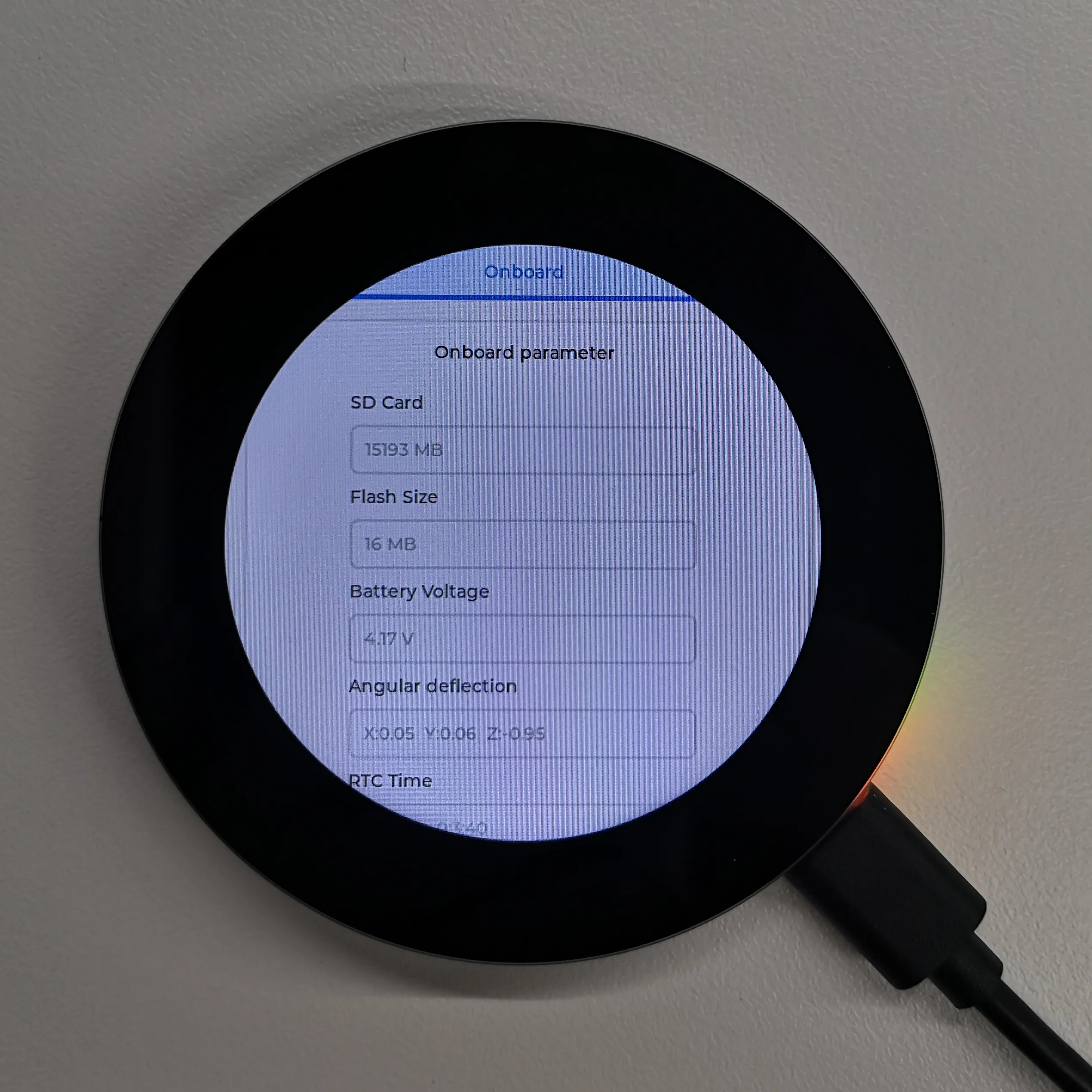
Operation Result
- LCD screen display:
- After the program is successfully flashed, use the BOOT button to control the interface:
- Single click: select the next control option
- Double click: select the previous control option
- Long press: control the selected control option
 |  |
|---|
- Parameter description:
| Parameter | Function | Description |
|---|---|---|
| SD Card | Displays the TF card size | Connect a TF card. If recognition fails, please format the TF card to FAT32 (if initial recognition fails, wait a moment and then reset to check again) |
| Flash Size | Displays the Flash size | Onboard 16MB Flash |
| Battery Voltage | Battery voltage | Battery voltage can be detected when a battery is connected |
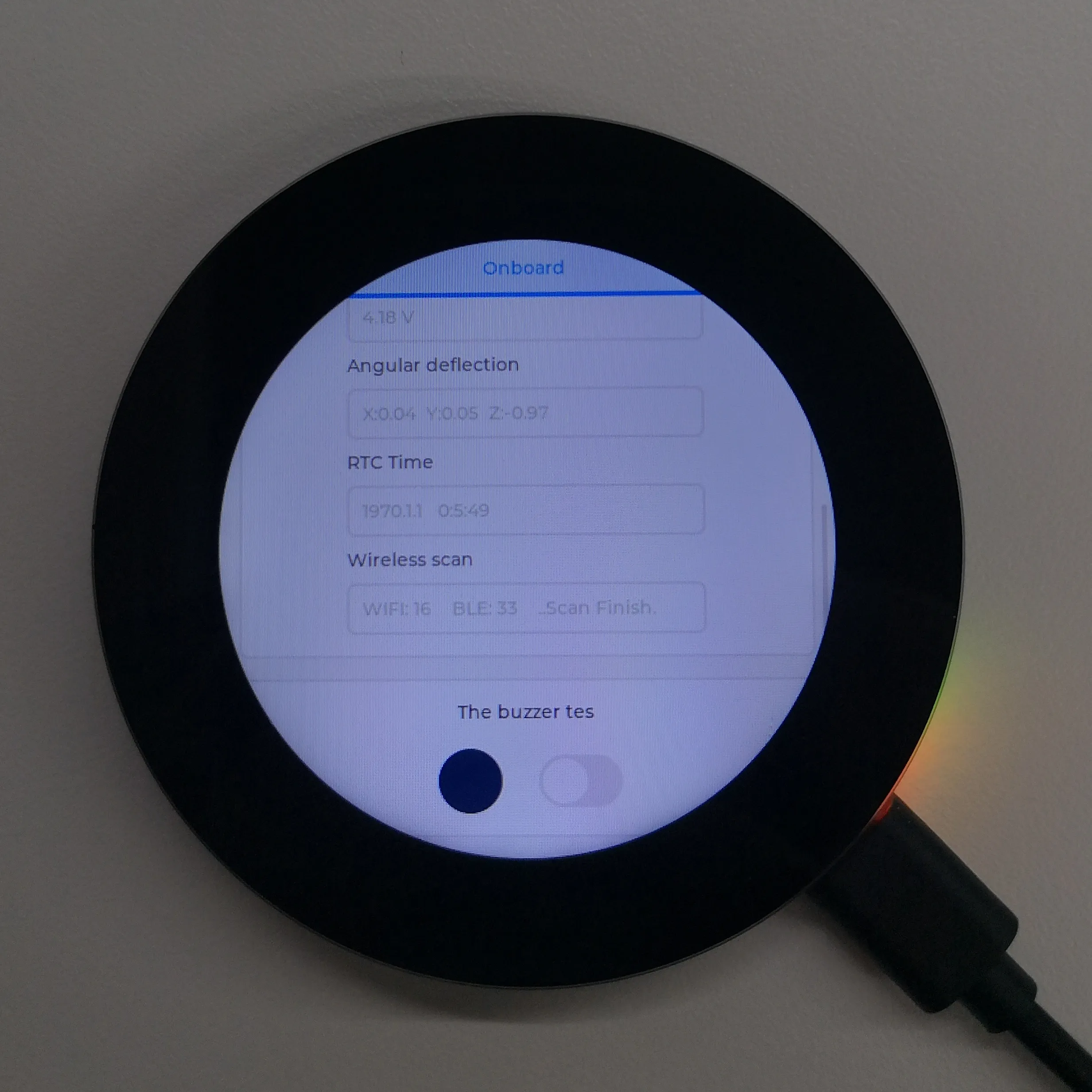
| Angular deflection | Displays the board's angular deviation | Displays deviation in three directions |
| RTC Time | Displays RTC time | The RTC time may not match the current time because data cannot be retained when power is off. To keep the RTC time accurate, you need to connect an RTC battery and update the RTC time |
| Wireless scan | Displays the number of Wi-Fi networks scanned | Scan ends with "Scan Finish" at the end |
| The buzzer test | Buzzer control page | Allows controlling the buzzer on/off |
| Backlight brightness | Brightness slider | Adjusts screen brightness |