Working with Arduino
This chapter includes the following sections. Please read as needed:
Arduino Getting Started
New to Arduino ESP32 development and looking for a quick start? We have prepared a comprehensive Getting Started Tutorial for you.
- Section 0: Getting to Know ESP32
- Section 1: Installing and Configuring Arduino IDE
- Section 2: Arduino Basics
- Section 3: Digital Output/Input
- Section 4: Analog Input
- Section 5: Pulse Width Modulation (PWM)
- Section 6: Serial Communication (UART)
- Section 7: I2C Communication
- Section 8: SPI Communication
- Section 9: Wi-Fi Basics
- Section 10: Web Server
- Section 11: Bluetooth
- Section 12: LVGL GUI Development
- Section 13: Comprehensive Project
Note: This tutorial uses the ESP32-S3-Zero as a reference example, and all hardware code is based on its pinout. Before you start, we recommend checking the pinout of your development board to ensure the pin configuration is correct.
Setting Up the Development Environment
1. Install and Configure the Arduino IDE
Please refer to the tutorial Install and Configure Arduino IDE to download and install the Arduino IDE and add ESP32 support.
This document corresponds to the examples/Arduino/ directory of the example package. Use Arduino-ESP32 3.3.12 and LVGL 9.5.0 according to the current project configuration. Please select the corresponding ESP32 core version in the Boards Manager, and obtain the matching example package from Resources and Documents.
2. Install Libraries
Check the "Sketchbook location" in "File → Preferences" in the Arduino IDE. Copy the matching library folders from the example package's libraries/ into the libraries/ directory at that location, keeping the library folder names. If libraries with the same names already exist, back them up first to avoid mixing different versions.
| Library Name | Description |
|---|---|
| RadioLib | LR1121 LoRa/LoRaWAN wireless communication driver |
| esp32_codec2 | Codec2 voice codec library (used by the walkie-talkie example) |
| GFX_Library_for_Arduino | SSD1309 OLED display driver |
| lvgl (9.5.0) | Lightweight graphics library (used by the 08 OLED example) |
| ESP32-audioI2S | MP3 decoding and I2S audio output library (used by the speaker example) |
| OneButton | Button event handling library (used by the button example) |
| SensorLib | PCF85063A RTC and BQ27220 fuel gauge driver (used by examples 06 and 07) |
Also copy the example package's libraries/lv_conf.h to libraries/ in the Arduino project folder so that it is at the same level as the lvgl/ folder. This configuration enables monochrome display and the fonts used by the examples. After completion, the directory relationship should be:
libraries/
├── lv_conf.h
├── lvgl/
├── SensorLib/
├── RadioLib/
└── …other matching libraries
Do not place only lv_conf.h in the directory where the .ino file is located. If the IDE reports that multiple libraries with the same name were found, check the actual library path in the compilation output.
3. Arduino Parameter Settings
Set the options in the "Tools" menu according to the table below. The menu text may differ slightly depending on the IDE language, so please verify the meaning of the options.
| Setting | Selected Value |
|---|---|
| Board | ESP32S3 Dev Module |
| Flash Size | 16MB (128Mb) |
| Partition Scheme | 16M Flash (3MB APP/9.9MB FATFS) (app3M_fat9M_16MB) |
| PSRAM | OPI PSRAM |
| USB CDC On Boot | Enabled |
| USB Mode | Hardware CDC and JTAG |
| Upload Mode | UART0 / Hardware CDC |
| Port | The serial port corresponding to this development board |
Connect the development board using a USB cable that supports data transfer, open the .ino file of the desired example, then compile and upload. When viewing the serial output, set the serial monitor baud rate to 115200. If the serial port number changes after entering download mode, please select the port again.
Example
The examples are located in the examples/Arduino directory of the example package. Keep all files such as .ino, .h, and .cpp within each example directory intact.
| Example | Description |
|---|---|
| 01_i2c_scan | Scan for device addresses on the I2C bus |
| 02_sd_mmc | Initialize the TF card and mount the FAT file system, read and write a test file |
| 03_button | Read the onboard button status and output button events over the serial port |
| 04_microphone | Read ES7210 microphone audio data via I2S |
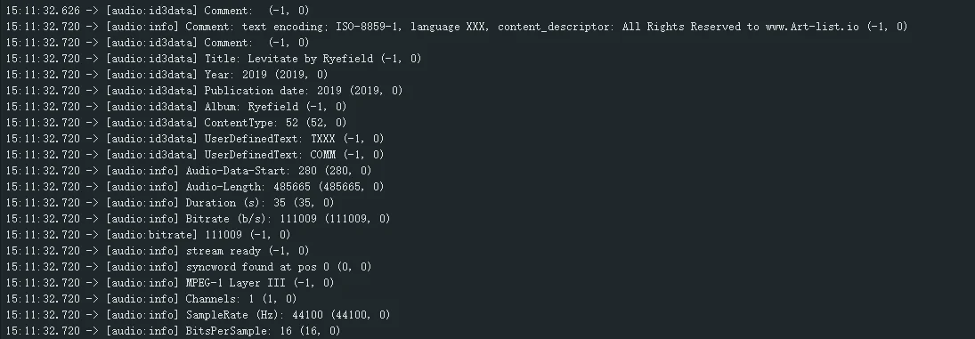
| 05_speaker | Read an MP3 file from the TF card and play it through the ES8311 speaker |
| 06_rtc_pcf85063 | Read and set the PCF85063A RTC time |
| 07_bat_bq27220 | Read the BQ27220 battery voltage, current, and remaining capacity |
| 08_oled_ssd1309 | Drive the SSD1309 OLED display and show an LVGL interface |
| 09_lora_ping_pong | LoRa transmit/receive test, with two devices performing Ping-Pong communication |
| 10_walkie_talkie | Use the onboard microphone, speaker, and LR1121 to implement half-duplex voice intercom |
| 11_lorawan_starter | LoRaWAN starter example, configuring a node to join a LoRaWAN network |
01_i2c_scan
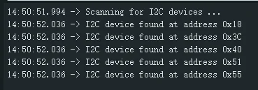
Scan for device addresses on the I2C bus and output the detection results over the serial port.
Code Explanation
Wire.begin(I2C_SDA_PIN, I2C_SCL_PIN): Initialize the I2C bus, SDA=GPIO13, SCL=GPIO14.- Perform a scan every 5 seconds, controlling the scan interval with
millis()timing. Wire.beginTransmission(address)/Wire.endTransmission(): Send a start signal to the specified address. A return value of 0 indicates that the device responded (exists).- The scan range is 0x01-0x7E, trying each address one by one. When a device is detected, output the address and index over the serial port.
- If no device is found, output "No I2C devices found".
Expected Behavior
02_sd_mmc
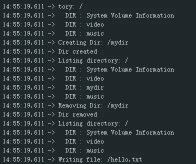
Initialize the TF card and mount the FAT file system, then create directories and read/write test files on the TF card.
Code Explanation
SD_MMC.setPins(CLK, CMD, D0): Configure the SDMMC pins (CLK=GPIO12, CMD=GPIO10, D0=GPIO11), using 1-line mode.SD_MMC.begin("/sdcard", true): Mount the TF card to/sdcard. The second parameter being true enables 1-line mode.SD_MMC.cardType()/SD_MMC.cardSize(): Get the card type (MMC/SDSC/SDHC) and total capacity.listDir(): List directory contents, distinguishing folders and files and showing file sizes.createDir()/removeDir(): Create and delete directories.writeFile()/appendFile()/readFile()/renameFile()/deleteFile(): File write, append, read, rename, and delete.testFileIO(): Read/write speed test, reading the entire file and writing 2048 blocks of 512-byte data, measuring elapsed time.SD_MMC.totalBytes()/SD_MMC.usedBytes(): Get total space and used space.
Expected Behavior
03_button
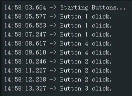
Read the status of the 4 onboard buttons (BOOT, PWR, MENU, PTT) and output button events over the serial port.
Code Explanation
- Use the
OneButtonlibrary to handle button events, supporting single click, double click, long press start, during long press, and long press stop. - 4 buttons: GPIO0 (BOOT), GPIO5 (MENU), GPIO4 (PWR), GPIO6 (PTT). The current program is configured as active low.
button.attachClick(): Register the single click event callback.button.attachDoubleClick(): Register the double click event callback.button.attachLongPressStart()/attachDuringLongPress()/attachLongPressStop(): Register long press related callbacks.- In
loop(), callbutton.tick()every 10ms to scan the button status. - When each of the 5 events for each button is triggered, output the corresponding event name and button index over the serial port.
Expected Behavior
04_microphone
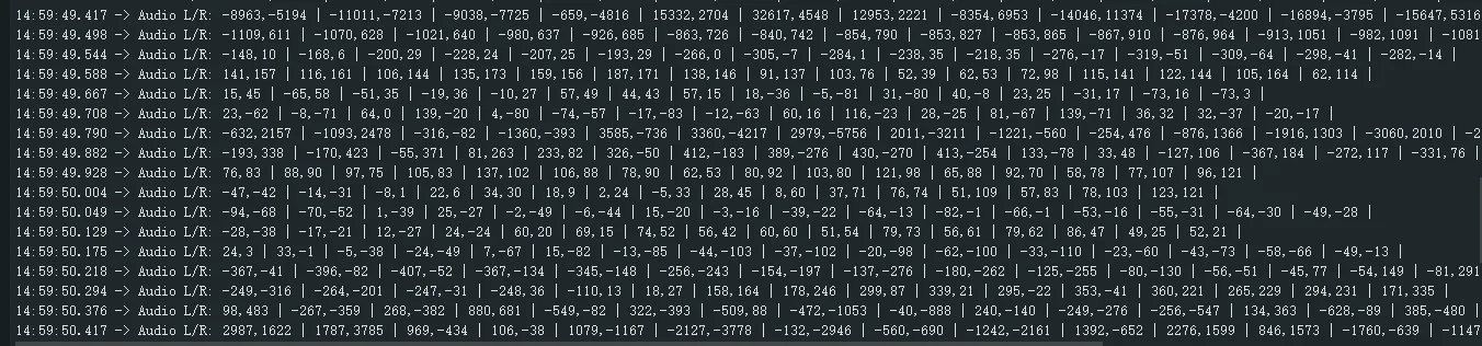
Read ES7210 microphone audio sampling data via the I2S interface and output the sample values over the serial port.
Code Explanation
- Use the ESP-IDF v5.x
i2s_tdm_config_tTDM mode to configure the I2S receive channel. i2s_new_channel(): Create an I2S channel, configuring only the RX (receive) direction.i2s_channel_init_tdm_mode(): Initialize TDM mode with 4 slots, 16-bit width, and 16kHz sample rate.Es7210Adc es7210: ES7210 microphone ADC driver object, configuring registers via I2C, with I2C address 0x40 and gain 30 dB.i2s_channel_read(): Read audio data from the I2S channel, blocking until data is ready (portMAX_DELAY).- The audio frame is 4 channels, 16-bit, with 1024 sample points. Take the first 16 sample points, formatting and outputting channel 0 (left) and channel 2 (right).
Expected Behavior
05_speaker
Read an MP3 file from the TF card and play it on the onboard speaker through the ES8311 audio DAC and amplifier.
Before running, you need to place an MP3 file in the music directory on the TF card.
Code Explanation
Es8311Codec codec: ES8311 audio Codec driver, configured via I2C, with a 48kHz sample rate and volume 85.Audio audio: ESP32-audioI2S library, used for MP3 decoding and I2S output, configuring the I2S pins viaaudio.setPinout()(BCLK=18, LRCK=21, SDOUT=16, MCLK=17).SD_MMC: TF card driver, 1-line mode (CLK=12, CMD=10, D0=11), mounted to/sdmmc.PA_CTRL (GPIO8): Amplifier enable pin. Outputting a high level turns on the amplifier.- A custom
ButtonStatestruct implements button debouncing and repeated press detection, with 25ms debounce, 550ms long press to trigger repeat, and 180ms repeat interval. - 4 button functions: MENU (GPIO5) play/pause, BOOT (GPIO0) previous track, PWR (GPIO4) next track, PTT (GPIO6) single click to increase volume / long press to repeatedly decrease volume.
scanMusicFolder(): Scan for MP3 files in the TF card/musicdirectory, up to 64 tracks, sorted by file name.audio.connecttoFS(SD_MMC, path): Load an MP3 file from the TF card and start playback.audio_eof_mp3()callback: Automatically switch to the next track when playback ends, looping playback.- Volume range 0-100, step 5, mapped to the Audio library's 21 volume levels.
Expected Behavior
06_rtc_pcf85063
Read and set the PCF85063A RTC time, with support for alarm function configuration.
Code Explanation
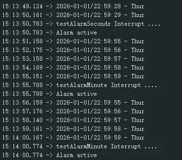
SensorPCF85063 rtc: PCF85063 RTC driver library, I2C address 0x51, SDA=GPIO13, SCL=GPIO14.rtc.begin(Wire, SDA, SCL): Initialize the RTC chip.rtc.setDateTime(year, month, day, hour, minute, second): Set the date and time.rtc.strftime(): Format and output the current time. The default format is "year-month-day/hour:minute:second - weekday".- The alarm test is divided into four stages, testing the second alarm, minute alarm, hour alarm, and day alarm in sequence:
rtc.setAlarmBySecond(30): Set a second-level alarm, triggered at 30 seconds.rtc.setAlarmByMinutes(0): Set a minute-level alarm, triggered at minute 0.rtc.setAlarmByHours(0): Set an hour-level alarm, triggered at hour 0.rtc.setAlarmByDays(1): Set a day-level alarm, triggered on day 1.
rtc.enableAlarm(): Enable the alarm. When the alarm is triggered, the GPIO7 pin goes low, detected viadigitalRead(SENSOR_IRQ).rtc.isAlarmActive()/rtc.resetAlarm(): Check and clear the alarm flag.
Expected Behavior
07_bat_bq27220
Read information such as the voltage, current, remaining capacity, and charging status of the BQ27220 battery fuel gauge.
Code Explanation
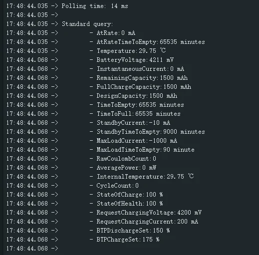
GaugeBQ27220 gauge: BQ27220 fuel gauge driver library, I2C address 0x55.gauge.begin(Wire, SDA, SCL): Initialize the fuel gauge chip.gauge.setNewCapacity(design, fullCharge): Set the battery design capacity and full charge capacity (the example sets it to 1500mAh). You need to enter configuration update mode to write it. Before running, adjust it according to the specifications of the actually installed battery. 1500mAh is not a statement of the standard battery capacity of the product.gauge.getOperationConfig(): Read the operation configuration register, outputting settings such as the temperature detection method, BAT_GD pin configuration, and sleep mode.gauge.refresh(): Refresh all register data, called every 3 seconds.- The output battery parameters include:
- Voltage (mV), current (mA), temperature (℃)
- Remaining capacity (mAh), full charge capacity (mAh), design capacity (mAh)
- SOC battery percentage (%), SOH health (%)
- Time remaining (minutes), time to full (minutes)
- Cycle count, average power (mW), requested charging voltage/current
- Operation status and battery status flags
Expected Behavior
08_oled_ssd1309
Drive the SSD1309 OLED display and show an LVGL graphical interface.
Code Explanation
Arduino_GFX_Library: Use the Arduino_GFX library to drive the OLED via the I2C interface (address 0x3C).- Comment note: The library does not have a dedicated SSD1309 driver, so the SSD1306 driver is used for compatibility (the two are basically register-compatible).
lv_init()/lv_tick_set_cb(millis_cb): Initialize LVGL and set the system tick callback.lv_display_create(128, 64): Create a 128x64 display device.my_disp_flush(): LVGL flush callback function, converting LVGL's 1-bit palette rendering result into the OLED's vertical video memory format, then drawing it viagfx->drawBitmap().- The display buffer size is
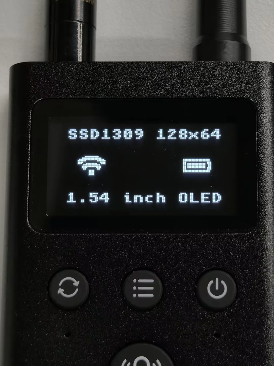
128 * 64 / 8 + 8(full-screen 1-bit data + palette), using full-screen rendering mode (LV_DISPLAY_RENDER_MODE_FULL). - LVGL interface: top title "SSD1309 128x64", WiFi icon on the left, battery icon on the right, and "1.54 inch OLED" at the bottom.
- In
loop(), calllv_timer_handler()to handle LVGL task scheduling.
Expected Behavior
09_lora_ping_pong
LoRa transmit/receive test, performing Ping-Pong communication between two devices to verify wireless link connectivity.
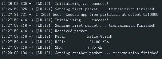
Two devices need to be flashed separately: the initiating end keeps #define INITIATING_NODE in the .ino, and the other end comments out that line. Both ends alternate between transmitting and receiving. The example defaults to 868 MHz. Please confirm that the board's RF version, antenna, and operating frequency band match, and that the modulation parameters on both ends are consistent.
Code Explanation
LR1121 radio = new Module(NSS, IRQ, NRST, BUSY, SPI, SPISettings(...)): Use the RadioLib LR1121 class, communicating via the SPI interface, with an SPI speed of 8MHz.- SPI pins: SCLK=GPIO40, MISO=GPIO46, MOSI=GPIO45, NSS=GPIO42, IRQ=GPIO38, NRST=GPIO39, BUSY=GPIO41.
radio.setRfSwitchTable(): Configure the RF switch table, controlling RX/TX path switching via DIO5/DIO6.radio.setFrequency(868.0): Operating frequency 868 MHz.radio.setOutputPower(22, true, RADIOLIB_LRXXXX_PA_RAMP_48U): Transmit power 22 dBm, 48us ramp.radio.setBandwidth(125.0, false)/radio.setSpreadingFactor(7)/radio.setCodingRate(5): 125kHz bandwidth, SF7, CR4/5.radio.setSyncWord(RADIOLIB_LR11X0_LORA_SYNC_WORD_PRIVATE): Set the private LoRa sync word.radio.setPreambleLength(8): Preamble length 8 symbols.radio.setIrqAction(setFlag): Register the interrupt callback, settingoperationDonewhen transmission/reception is complete.- Initiating end (
INITIATING_NODEmacro): Send "Hello World!" first, then switch to receiving and wait for a reply. - Receiving end: Start receiving. After receiving, output the data, RSSI, and SNR, then reply after a 1-second delay, forming a Ping-Pong loop.
Expected Behavior
10_walkie_talkie
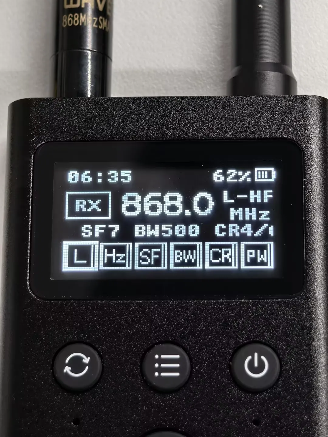
Use the onboard microphone, speaker, OLED, and LR1121 to implement half-duplex voice intercom, using Codec2 3200 bps voice encoding. Hold the PTT button to transmit and release it to receive.
Requires two devices used together. Depends on the RadioLib, esp32_codec2, and GFX_Library_for_Arduino libraries. The frequency band, frequency, modulation method, and related parameters on both ends should be consistent; the default HF configuration is 868 MHz, which should be selected according to the actual RF version and antenna.
Code Explanation
AudioPipeline: Audio pipeline module, managing microphone capture (ES7210, TDM mode, 8kHz sample rate), Codec2 3200bps encoding/decoding, and speaker playback (ES8311).RadioRuntime: LR1121 RF runtime management, supporting both LoRa and GFSK modulation methods, defaulting to 868 MHz, with a transmit data block of 240 bytes.Ui/Sensors: Use Arduino_GFX and a monochrome canvas to draw the 128×64 OLED interface, and collect PCF85063 RTC and BQ27220 fuel gauge data. This walkie-talkie interface does not use LVGL.AppState/Settings: Application state management and parameter saving (NVS), supporting persistence of settings such as frequency, modulation method, and volume.- PTT button controls half-duplex mode: press to enter transmit (capture→AGC→encode→send), release to enter receive (receive→decode→noise reduction→playback).
- Transmitting end: AGC automatic gain control, high-pass filtering, soft-knee limiting; receiving end: noise gate, soft-knee limiting, playback gain.
- Supports low-power Light Sleep: automatically sleeps after 30 seconds of no operation. Before sleeping, clear the audio buffer, turn off the display, and configure LoRa receive wake-up.
- Wake-up sources: the four buttons PTT, MENU, PWR, and BOOT, as well as the LR1121 interrupt pin (high-level wake-up). The active level and wake-up configuration of PWR need to be verified according to the Button Description.
- Audio buffering: 160 samples × 20 frames, supporting continuous voice stream transmission.
Interface Illustration (the layout may differ across frameworks and versions; the actual running interface shall prevail)
11_lorawan_starter
LoRaWAN starter example, configuring a node to join a LoRaWAN network via OTAA and send uplink data.
You need to register the device on a LoRaWAN network server and configure JoinEUI (called AppEUI on some platforms), DevEUI, NwkKey, and AppKey according to the config.h template. The key configuration should be consistent with the selected LoRaWAN version and server requirements. You also need a LoRaWAN gateway already connected to that server; the default EU868 region should match the actual board, antenna, and network region.
Code Explanation
- Use RadioLib's
LoRaWANNodeclass to implement the LoRaWAN protocol stack and drive the LR1121 RF chip. LR1121 radio = new Module(42, 38, 39, 41, SPI, SPISettings(8000000, MSBFIRST, SPI_MODE0)): NSS=42, IRQ=38, NRST=39, BUSY=41, SPI rate 8MHz.radio.setRfSwitchTable(): Configure the DIO5/DIO6 RF switch table, distinguishing modes such as standby, receive, and transmit (HP/HF).radio.setTCXO(3.0): Configure the TCXO temperature-compensated crystal oscillator voltage to 3.0V.radio.setOutputPower(14, true, 48): The example sets the transmit power to 14 dBm and uses the high-power PA path; the remaining parameters are interpreted according to the definitions of the matching RadioLib interface.LoRaWANNode node(&radio, &Region, subBand): Create a LoRaWAN node, frequency band EU868, sub-band 0.Preferences(NVS): Save the LoRaWAN nonce and session data, restoring the state after restart to avoid repeatedly joining the network.saveLoRaWANState()/restoreLoRaWANState(): Save and restore the network join state to NVS.node.beginOTAA(joinEUI, devEUI, nwkKey, appKey): Initialize the OTAA node parameters (DevEUI, JoinEUI, NwkKey, AppKey).node.activateOTAA(): Execute the OTAA join procedure, returning a new session or restoring the session state.node.sendReceive(): Send uplink data and wait for a downlink response in the RX1/RX2 windows.- Uplink period: Send once every 5 minutes, with a payload of 3 bytes of random data (simulating a sensor value).
printHex()/printAscii(): Format a byte array into a hexadecimal or ASCII string for output, used to view the received downlink data.