Working with ESP-IDF
This chapter includes the following sections. Please read as needed:
ESP-IDF Getting Started
New to ESP32 ESP-IDF development and looking to get started quickly? We have prepared a general Getting Started Tutorial for you.
- Section 1: Environment Setup
- Section 2: Running Examples
- Section 3: Creating a Project
- Section 4: Using Components
- Section 5: Debugging
- Section 6: FreeRTOS
- Section 7: Peripherals
- Section 8: Wi-Fi Programming
- Section 9: BLE Programming
Please Note: This tutorial uses the ESP32-S3-Zero as a teaching example, and all hardware code is based on its pinout. Before you start, it is recommended that you check the pinout of your development board to ensure the pin configuration is correct.
Set Up the Development Environment
This document corresponds to the examples/esp-idf/ directory of the current example package. The stable versions configured for the project are ESP-IDF v5.5.5 / v6.1, and the component requirement is >=5.5.5,<6.3. The initial setup steps below give the tool dependencies for these two versions respectively. Please choose one environment to use. The repository also has a fixed 6.2 development-version compatibility channel, which is not used as the default environment for this starter tutorial.
The following guide uses Windows as an example, demonstrating development using VS Code + the ESP-IDF extension. macOS and Linux users should refer to the official documentation.
The screenshots in this section use ESP-IDF V5.5.2 as an example. When installing, please select the ESP-IDF version that matches your board's example.
Install the ESP-IDF Development Environment
-
Download the installation manager from the ESP-IDF Installation Manager page. This is Espressif's latest cross-platform installer. The following steps demonstrate how to use its offline installation feature.
Click the Offline Installer tab on the page, then select Windows as the operating system and the ESP-IDF version you need (the version shown in the screenshot is for reference only — choose the version that fits your actual needs).
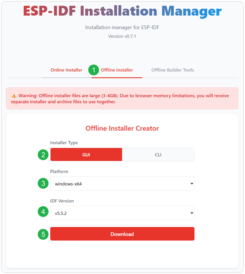
After confirming your selection, click the download button. The browser will automatically download two files: the ESP-IDF Offline Package (.zst) and the ESP-IDF Installer (.exe).
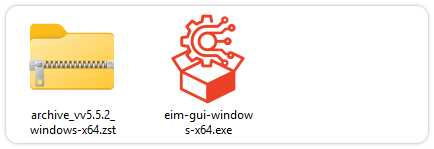
Please wait for both files to finish downloading.
-
Once the download is complete, double-click to run the ESP-IDF Installer (eim-gui-windows-x64.exe).
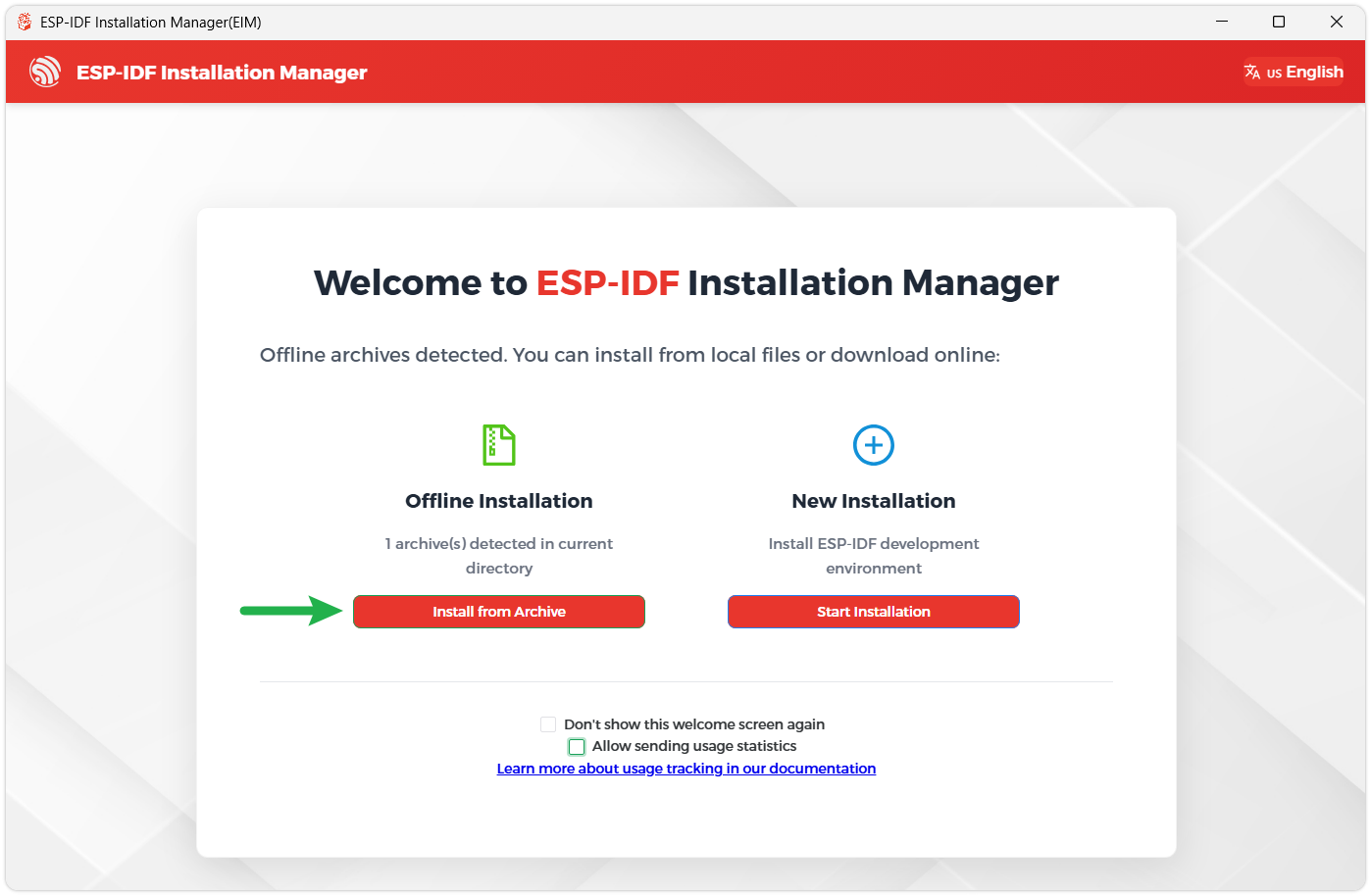
The installer will automatically detect if the offline package exists in the same directory. Click Install from archive.
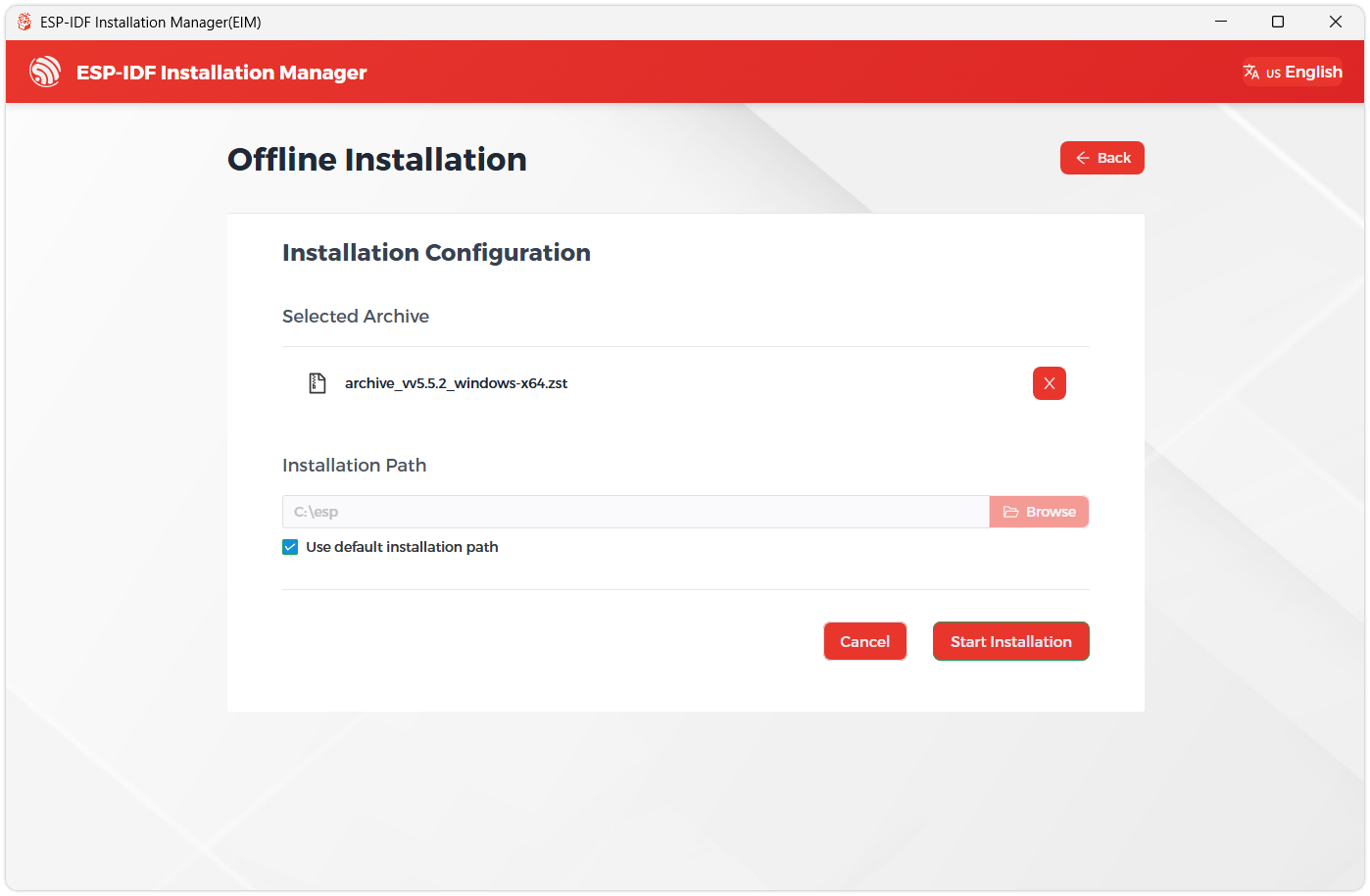
Next, select the installation path. We recommend using the default path. If you need to customize it, ensure the path does not contain Chinese characters or spaces. Click Start installation to proceed.
-
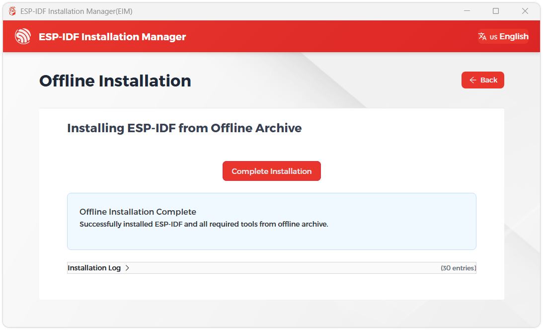
When you see the following screen, the ESP-IDF installation is successful.
-
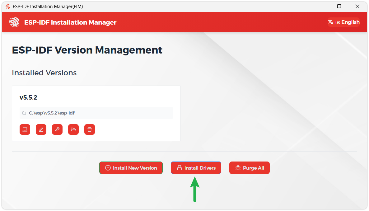
We recommend installing the drivers as well. Click Finish installation, then select Install driver.
Install Visual Studio Code and the ESP-IDF Extension
-
Download and install Visual Studio Code.
-
During installation, it is recommended to check Add "Open with Code" action to Windows Explorer file context menu to facilitate opening project folders quickly.
-
In VS Code, click the Extensions icon
 in the Activity Bar on the side (or use the shortcut Ctrl + Shift + X) to open the Extensions view.
 -
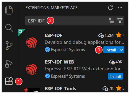
Enter ESP-IDF in the search box, locate the ESP-IDF extension, and click Install.
-
For ESP-IDF extension versions ≥ 2.0, the extension will automatically detect and recognize the ESP-IDF environment installed in the previous steps, requiring no manual configuration.
1. Prepare the Complete Example Package
Obtain the example package from Resources and Documents and extract it completely, keeping the relative positions of directories such as examples/ and config/. Each example has its own project entry point, but depends on repository-level shared configuration, so you cannot copy just one example folder.
2. Install the Board Manager Extension
First activate the selected ESP-IDF environment, or use VS Code's "ESP-IDF: Open ESP-IDF Terminal" to open a terminal for that environment. bmgr is an extension command, and it must be installed separately for each ESP-IDF Python environment.
Windows PowerShell or Ubuntu Bash, ESP-IDF v5.5.5 environment:
python -m pip install idf-component-manager==2.5.0 esp-bmgr-assist==0.8.3
Windows PowerShell or Ubuntu Bash, ESP-IDF v6.1 environment:
python -m pip install idf-component-manager==3.0.3 esp-bmgr-assist==0.8.3
3. Select the Board Definition and Build
The following uses a freshly extracted 01_i2c_scan as an example. Run from the root directory of the example package; when using other examples, replace the directory name.
Windows PowerShell or Ubuntu Bash (with the ESP-IDF environment activated):
cd examples/esp-idf/01_i2c_scan
idf.py set-target esp32s3
idf.py reconfigure
idf.py bmgr -l
idf.py bmgr -b esp32_s3_lr1121_oled_1_54_xf
idf.py build
reconfigure resolves and downloads dependencies; bmgr generates the required code based on the board definition in the project. After the selection is complete, you can open that example directory in VS Code to continue compiling and flashing. The board definition name is a project identifier, and the actual RF version and operating frequency band still need to be selected according to the hardware in use.
The above steps apply to the first build. If you already have a custom sdkconfig, back it up first; the first board definition selection may back up the old configuration to components/gen_bmgr_codes/sdkconfig.bmgr_board.old and remove the original configuration. When switching ESP-IDF environments, you should use a new build directory and handle the existing dependency lock file according to the example package's docs/board-manager.md.
4. Flash and View Logs
Replace the port in the commands with the actual port on your machine.
Windows PowerShell:
idf.py -p COM5 flash monitor
Ubuntu Bash:
idf.py -p /dev/ttyACM0 flash monitor
Use Ctrl+] to exit the serial monitor. If you cannot enter download mode, refer to the FAQ.
Example
The examples are located in examples/esp-idf/. Please complete the above dependency installation and board definition selection first, then compile and flash in the corresponding project directory. The board-level adaptation code and YAML configuration are located in each project's components/ws_board/.
| Example | Description |
|---|---|
| 01_i2c_scan | I2C toolset, providing the i2cdetect, i2cget, i2cset, and i2cdump commands |
| 02_sd_mmc | Initialize the TF card and mount the FAT file system, read and write a test file |
| 03_button | Read the onboard button status and register click callback events |
| 04_microphone | Read ES7210 microphone audio data via I2S |
| 05_speaker | Read an MP3 file from the TF card and play it through the ES8311 speaker |
| 06_rtc_pcf85063 | Read and set the PCF85063A RTC time |
| 07_bat_bq27220 | Read the BQ27220 battery voltage, current, and remaining capacity |
| 08_oled_ssd1309 | Drive the SSD1309 OLED display and show an LVGL interface |
| 09_lora_ping_pong | LoRa transmit/receive test, with two devices performing Ping-Pong communication |
| 10_walkie_talkie | Use the onboard microphone, speaker, and LR1121 to implement half-duplex voice intercom |
| 11_lorawan_starter | LoRaWAN starter example, joining a network via OTAA and periodically reporting data |
01_i2c_scan
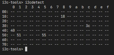
Provides an I2C toolset, supporting the i2cdetect, i2cget, i2cset, and i2cdump commands, and interacts with I2C devices through the serial command line.
Code Explanation
ws_board_init()/bsp_i2c_get_handle(): Initialize board-level management and obtain the shared I2C Master bus handle, SDA=GPIO13, SCL=GPIO14.esp_console_new_repl_usb_serial_jtag(): Start the serial REPL interactive environment, with the prompti2c-tools>.register_i2ctools(): Register console commands such as i2cdetect, i2cget, i2cset, and i2cdump.i2cdetect: The current implementation traverses the 0x00-0x7F address range (including reserved addresses), determining whether a device exists by its ACK response.i2cget/i2cset: Read or write the register value at the specified device address.i2cdump: Continuously dump the register area of the specified device.
Expected Behavior
02_sd_mmc
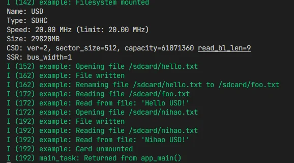
Initialize the TF card and mount the FAT file system, create directories and read/write test files on the TF card, and print the card information.
Code Explanation
bsp_sdcard_mount(): Initialize the TF card through the board-level adaptation layer and mount the FAT file system to/sdcard.- The board definition configures CLK=GPIO12, CMD=GPIO10, D0=GPIO11, using 1-line SDMMC, with a default clock of 20 MHz. This board does not have the data lines required for 4-line mode connected.
- If mounting fails, the TF card is not automatically formatted; please prepare a card using a supported FAT file system in advance.
fopen()/fputs()/fgets()/fclose(): Use standard C library functions to operate on files.- Example flow: write hello.txt → rename to foo.txt → read and verify → write nihao.txt → read and verify → unmount the TF card.
sdmmc_card_print_info(): Print information such as the TF card name, capacity, and speed class.
Expected Behavior
03_button
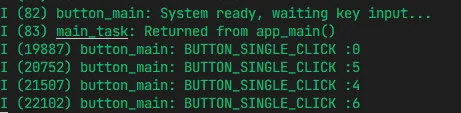
Obtain the button devices through Board Manager, register single click and PTT double click callbacks, and output button events over the serial port.
Code Explanation
ws_button_for_gpio(): Obtain the button object for the corresponding GPIO; the pin and active level are uniformly configured by the board definition.iot_button_register_cb(): The current example registers a single click callback for 4 buttons and additionally registers a double click callback for PTT.- 4 buttons: GPIO0 (BOOT), GPIO5 (MENU), GPIO6 (PTT, supports double click), GPIO4 (PWR).
- Callback function
button_event_cb(): Obtain the event type viaiot_button_get_event(), and output the event name and GPIO number over the serial port. - The callback function retains the handling branches for events such as long press duration and repeat count, but the current example does not register these events; when they need to be demonstrated, the corresponding callback registration should be added first.
Expected Behavior
04_microphone
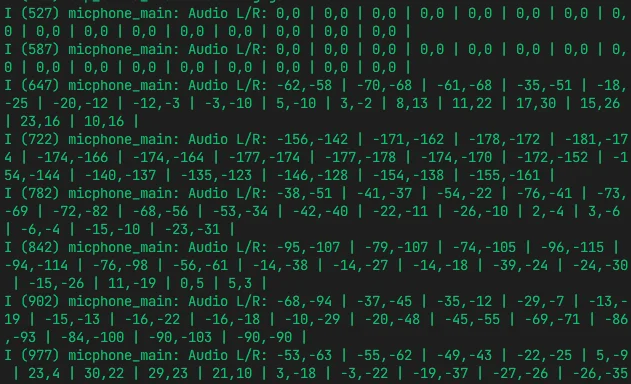
Read ES7210 microphone audio sampling data via the I2S interface and output the sample values over the serial port.
Code Explanation
bsp_extra_codec_init(): Initialize the ES7210 audio Codec, configuring the I2S interface and sample rate.bsp_extra_codec_gain_set(30, NULL): Set the microphone gain to 30dB.bsp_extra_i2s_read(): Read audio data from the I2S receive buffer, blocking until data is ready.- The audio frame is 4 channels, 16-bit, with 1024 sample points, and the array size is
FRAME_SIZE * CHANNEL_COUNT. - In the loop, one frame of data is read each time, taking the left channel (channel 0) and right channel (channel 2) values of the first 16 sample points and formatting and outputting them.
Expected Behavior
05_speaker
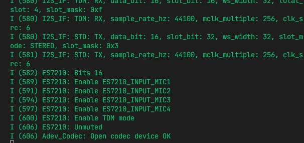
Mount the TF card, scan for MP3 files in the music directory, and play them on the onboard speaker through the ES8311 audio DAC and amplifier.
Before running, you need to place an MP3 file in the music directory on the TF card.
Code Explanation
bsp_sdcard_mount(): Mount the TF card toBSP_SD_MOUNT_POINT.list_files(): Traverse the TF cardmusicdirectory and collect the paths and file names of all.mp3files into an array.bsp_extra_codec_init()/bsp_extra_codec_volume_set(): Initialize the ES8311 audio Codec and set the default volume.bsp_extra_player_init()/bsp_extra_player_play_file(): Initialize the MP3 player and play the specified file.- 4 button controls: GPIO0 (UP, next track), GPIO4 (DOWN, previous track); for the active level see Button Description, GPIO5 (RESUME, play/pause), GPIO6 (VOLUME, single click to increase volume / double click to decrease volume, step 5%).
speaker_callback(): Playback end callback, automatically switching to the next track and looping playback.
Expected Behavior
06_rtc_pcf85063
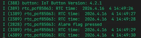
Initialize the PCF85063A RTC, set the default time and alarm, and periodically read and output the current time.
Code Explanation
bsp_rtc_init(): Initialize the PCF85063A RTC chip via I2C.bsp_set_rtc_time_date(rtc_time): Set the initial time (year, month, day, weekday, hour, minute, second).bsp_set_rtc_alarm_time(rtc_time): Set the alarm time, with the alarm seconds set to 29 seconds.bsp_enable_rtc_alarm(): Enable the alarm function. When the alarm is triggered, the GPIO7 pin generates an interrupt.- GPIO7 is configured as a button input. When the alarm is triggered, output a notification through the
BUTTON_PRESS_DOWNevent callback. - The main loop reads the current time once per second, formatting it into a string via
bsp_datetime_to_str()and outputting it over the serial port.
Expected Behavior
07_bat_bq27220
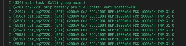
Read and output information such as the voltage, current, remaining capacity, and charging status of the BQ27220 battery fuel gauge.
Code Explanation
bsp_bat_init(1000): Initialize the BQ27220 fuel gauge, with the parameter being the battery design capacity 1000mAh. It should be adjusted according to the specifications of the actually installed battery; this value is not a statement of the product's standard battery capacity.bsp_get_bat_info(&bat_info): Read the battery information into thebsp_bat_info_tstruct.bat_info.mv: Battery voltage (mV).bat_info.ma: Battery current (mA), positive when charging and negative when discharging.bat_info.soc: Remaining battery percentage (State of Charge %).bat_info.mah_rem: Remaining capacity (mAh).bat_info.mah_fcc: Full charge capacity (mAh, Full Charge Capacity).bat_info.tc: Battery temperature (°C).- The main loop reads once per second and formats and outputs all parameters.
Expected Behavior
08_oled_ssd1309
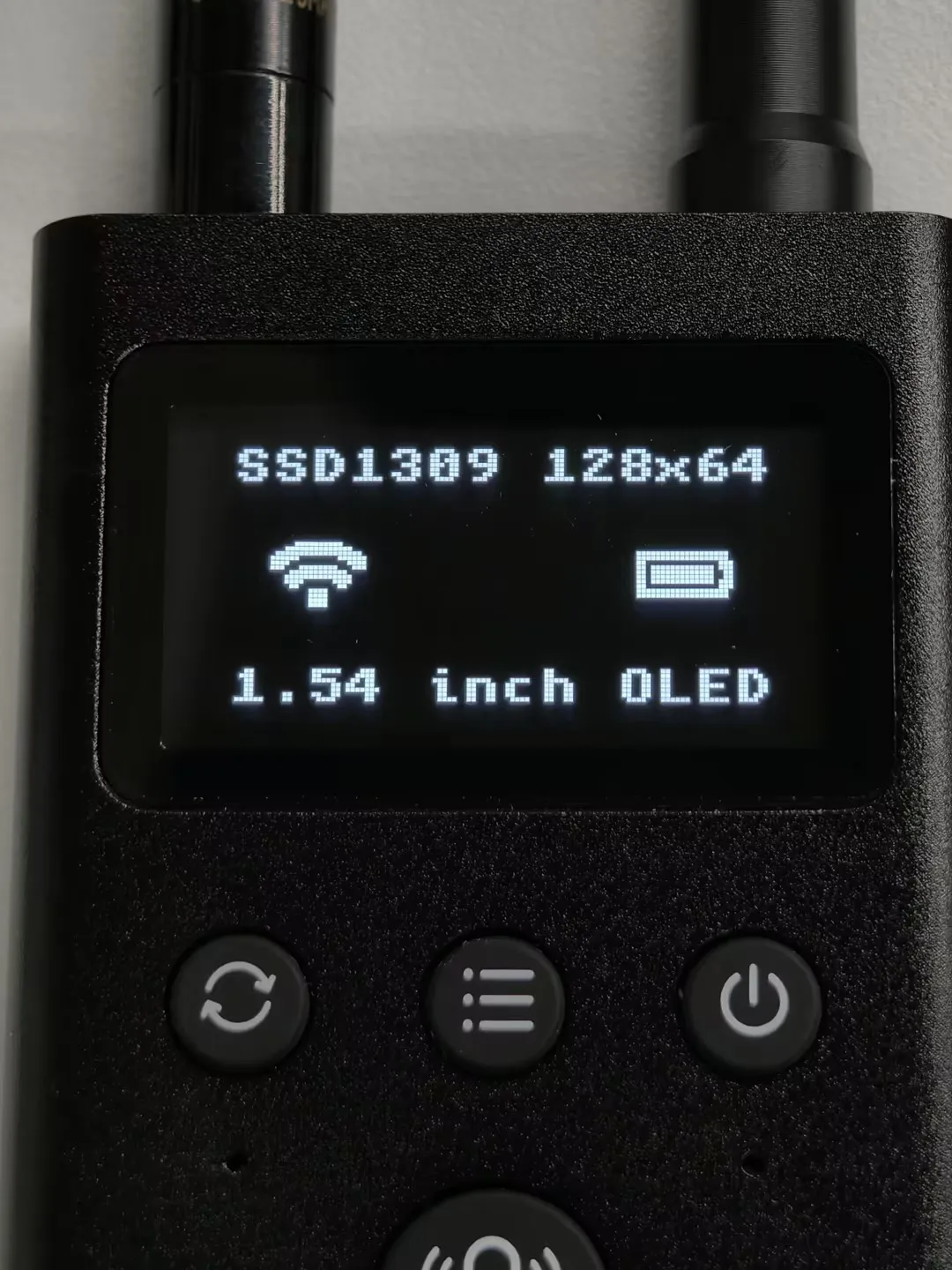
Start the BSP display driver, drive the SSD1309 OLED display, and show an LVGL graphical interface.
Code Explanation
bsp_display_start(): Initialize the I2C OLED display driver and LVGL, returning the display device handle.bsp_display_lock(-1): Acquire the LVGL display lock. -1 means wait indefinitely, ensuring multi-thread safety.lv_display_get_screen_active(display): Get the current active screen object of the specified display device.lv_label_create(): Create text labels, displaying the title "SSD1309 128x64" and the bottom text "1.54 inch OLED" respectively.lv_image_create()+lv_image_set_src(): Create image widgets, displaying LVGL built-in icons (Wi-Fi, battery full).lv_obj_align(): Set the alignment of the widgets (top center, middle left, middle right, bottom center).bsp_display_unlock(): Release the display lock.
Expected Behavior
09_lora_ping_pong
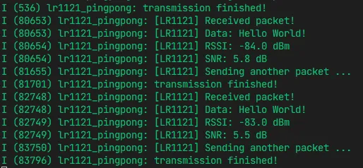
Use RadioLib to perform transmit/receive testing in LoRa packet mode, with two devices performing Ping-Pong communication.
Requires two devices used together: the initiating end keeps #define INITIATING_NODE in main/main.cpp, and the other end comments out that line. Both ends alternate between transmitting and receiving. The example defaults to 868 MHz. Please confirm that the board's RF version, antenna, and operating frequency band match, and keep the parameters on both ends consistent.
Code Explanation
LR1121 radio(&radio_module): Use RadioLib's LR1121 class to drive the RF chip, encapsulating the SPI interface throughModuleandEspHal.radio.setRfSwitchTable(): Configure the RF switch table, controlling RX/TX path switching via DIO5/DIO6.radio.setFrequency(868.0): Set the operating frequency to 868 MHz.radio.setOutputPower(22): Set the transmit power to 22 dBm.radio.setBandwidth(125.0)/radio.setSpreadingFactor(7)/radio.setCodingRate(5): Set the LoRa modulation parameters (125kHz bandwidth, SF7, CR4/5).radio.setIrqAction(set_flag): Register the interrupt callback, setting theoperation_doneflag when transmission/reception is complete.- Initiating end (
INITIATING_NODEmacro definition): Send "Hello World!" first, then switch to receive mode and wait for a reply after sending is complete. - Receiving end: Start receiving. After receiving the data, output the content, RSSI, and SNR, then reply with the same data after a 1-second delay.
Expected Behavior
10_walkie_talkie
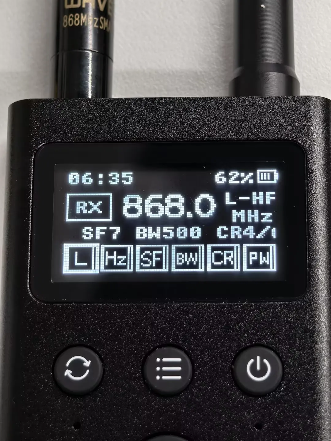
Use the onboard microphone, speaker, OLED, and LR1121 to implement half-duplex voice intercom, using Codec2 3200 bps voice encoding. Hold the PTT button to transmit and release it to receive.
Requires two devices used together. The example includes the ws_board board-level adaptation and the esp32_codec2 component, and the interface uses LVGL. The frequency band, frequency, modulation method, and related parameters on both ends should be consistent, and should match the actual board and antenna.
Code Explanation
audio_pipeline: Audio pipeline module, responsible for microphone capture, Codec2 encoding, decoding, and speaker playback.radio_device/radio_runtime: LR1121 RF driver and runtime management, handling LoRa packet transmission and reception.ui: Draws the OLED interface based on LVGL, displaying information such as wireless parameters, PTT status, time, and battery level.peripheral_guard: Provides a shared mutex to coordinate access to peripherals such as the wireless module, RTC, fuel gauge, and display-side I2C.- PTT button controls the working mode: press to enter transmit mode (I2S capture → Codec2 encoding → LR1121 transmission), release to enter receive mode (LR1121 reception → Codec2 decoding → I2S playback).
- Supports low-power sleep: automatically enters Light Sleep after 30 seconds of no operation, waking up via button or LoRa interrupt. The PWR level and wake-up configuration need to be verified according to the Button Description.
nvs_flash_init(): Initialize NVS, used to save configuration parameters such as channel and volume.
Interface Illustration (the layout may differ across frameworks and versions; the actual running interface shall prevail)
11_lorawan_starter
LoRaWAN starter example, using RadioLib's LoRaWANNode class to join a LoRaWAN network via OTAA, periodically sending uplink data and receiving downlink data, and using NVS to save the session state for reconnection after power loss.
Before running, you need to fill in the LoRaWAN credentials (JoinEUI, DevEUI, AppKey, NwkKey) in main/config.h. Production credentials can be configured through the lorawan_secrets.h file and excluded from version control. You need to register the device on a network server first and use a gateway already connected to that server; the region configuration (default EU868) should be consistent with the board, antenna, and network. JoinEUI is called AppEUI on some platforms, and the key fields should be filled in according to the selected LoRaWAN version and server requirements.
Code Explanation
EspHal: Encapsulates ESP-IDF's SPI/GPIO/timer interfaces, providing a hardware abstraction layer for RadioLib and configuring the SPI bus pins and clock rate.LR1121 radio(&radio_module): Initialize the LR1121 RF module throughModuleandEspHal.radio.setRfSwitchTable(rfswitch_dio_pins, rfswitch_table): Configure the RF switch table, controlling RX/TX path switching via DIO5/DIO6.LoRaWANNode node(&radio, &lorawan_region, lorawan_sub_band): Create a LoRaWAN node, configuring the region as EU868 and sub-band 0.node.beginOTAA(join_eui, dev_eui, nwk_key, app_key): Initialize the node using OTAA, passing in JoinEUI, DevEUI, NwkKey, and AppKey.node.activateOTAA(): Execute the OTAA join procedure. ReturningRADIOLIB_LORAWAN_NEW_SESSIONindicates a new session, andRADIOLIB_LORAWAN_SESSION_RESTOREDindicates the session was restored from NVS.restore_lorawan_state()/save_lorawan_state(): Save and restore the LoRaWAN session state (DevNonce and session context) via NVS, avoiding rejoining the network on every restart.node.sendReceive(uplinkPayload, sizeof(uplinkPayload), 1, downlink, &downlinkLen): Send 3 bytes of uplink data (random value val1 + 2-byte val2) and wait for downlink data. A return value greater than 0 indicates that downlink data was received.uplink_interval_seconds = 5 * 60: Uplink interval 5 minutes.- When downlink data is received, output the receive window number, data length, HEX dump, and ASCII content.