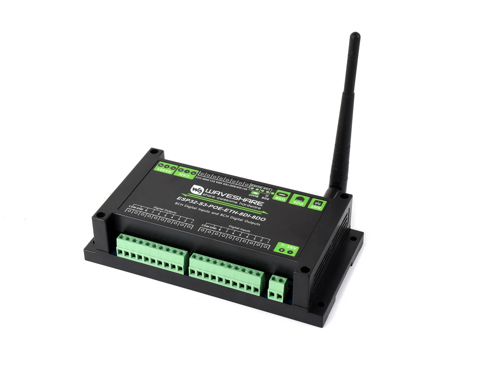
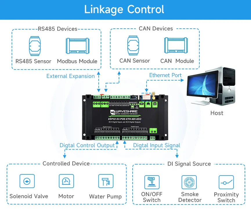
The ESP32-S3-POE-ETH-8DI-8DO is an industrial-grade 8-channel network digital input and digital output device based on the ESP32-S3 main controller, supporting Wi-Fi, Bluetooth, RS485, CAN, and Ethernet. It features built-in power isolation, optocoupler isolation, and other protection circuits, making it suitable for AIoT control applications.
| SKU | Product |
|---|
| 32108 | ESP32-S3-POE-ETH-8DI-8DO |
If you are looking for:
- Coding with AI tools: Click Ask AI and select an AI tool to ask questions about this page, or choose Copy page to copy its content and paste it into an AI tool for coding assistance.
- Datasheets and example code: See Resources
- Arduino development: See Working with Arduino
- Troubleshooting: See Product FAQ or contact Technical Support
Features
- Based on the ESP32-S3 microcontroller, with a built-in Xtensa 32-bit LX7 dual-core processor running at up to 240MHz
- Integrated 2.4 GHz Wi-Fi and Bluetooth Low Energy (Bluetooth LE) dual-mode wireless communication
- Outputs use Darlington transistors with optocoupler isolation, with a sink current of up to 500 mA, and built-in flyback diode protection
- Digital inputs feature bidirectional optocoupler isolation, support both dry-contact and active switch inputs, and digital outputs support linkage mode control with switch inputs
- Onboard isolated RS485 interface, convenient for expanding and connecting various RS485 Modbus industrial expansion modules or sensors
- Onboard isolated CAN interface, convenient for expanding and connecting various CAN devices
- Onboard pin header interface, allowing connection of other devices
- Onboard USB Type-C interface, can be used for power supply and download/debugging, convenient for development
- Onboard power supply screw terminal, supports 7-36V wide voltage input, suitable for industrial applications
- Onboard RTC clock chip, supporting scheduled tasks
- Onboard W5500 Ethernet chip, expanding 10/100Mbps network connectivity via the SPI interface
- Onboard PoE module for Power over Ethernet (IEEE 802.3af compliant)
- Onboard optocoupler isolation, preventing external circuits from interfering with the control chip
- Onboard digital isolation to avoid external signal interference with the control chip
- Onboard integrated isolated power supply provides stable isolated voltage; the isolated side requires no additional power
- Onboard TF card slot for external storage of images or files
- Onboard buzzer, RGB LED, power, RS485 transmit/receive indicators, and CAN indicator, convenient for sensing the device's operating status
- Rail-mounted ABS protective enclosure, easy to install, safe to use
Specifications
| Parameter | Value |
|---|
| Supply Voltage | 7-36V (or 5V/1A Type-C port) |
| Number of Digital Output Channels | 8 channels |
| Number of Digital Input Channels | 8 channels |
| Wiring Port | Type-C |
| Communication Protocol | USB protocol |
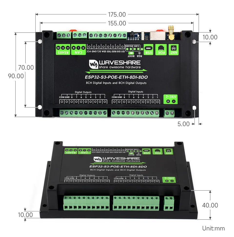
| Product Dimensions | 90 (H) x 175 (V) mm |
Interface Introduction
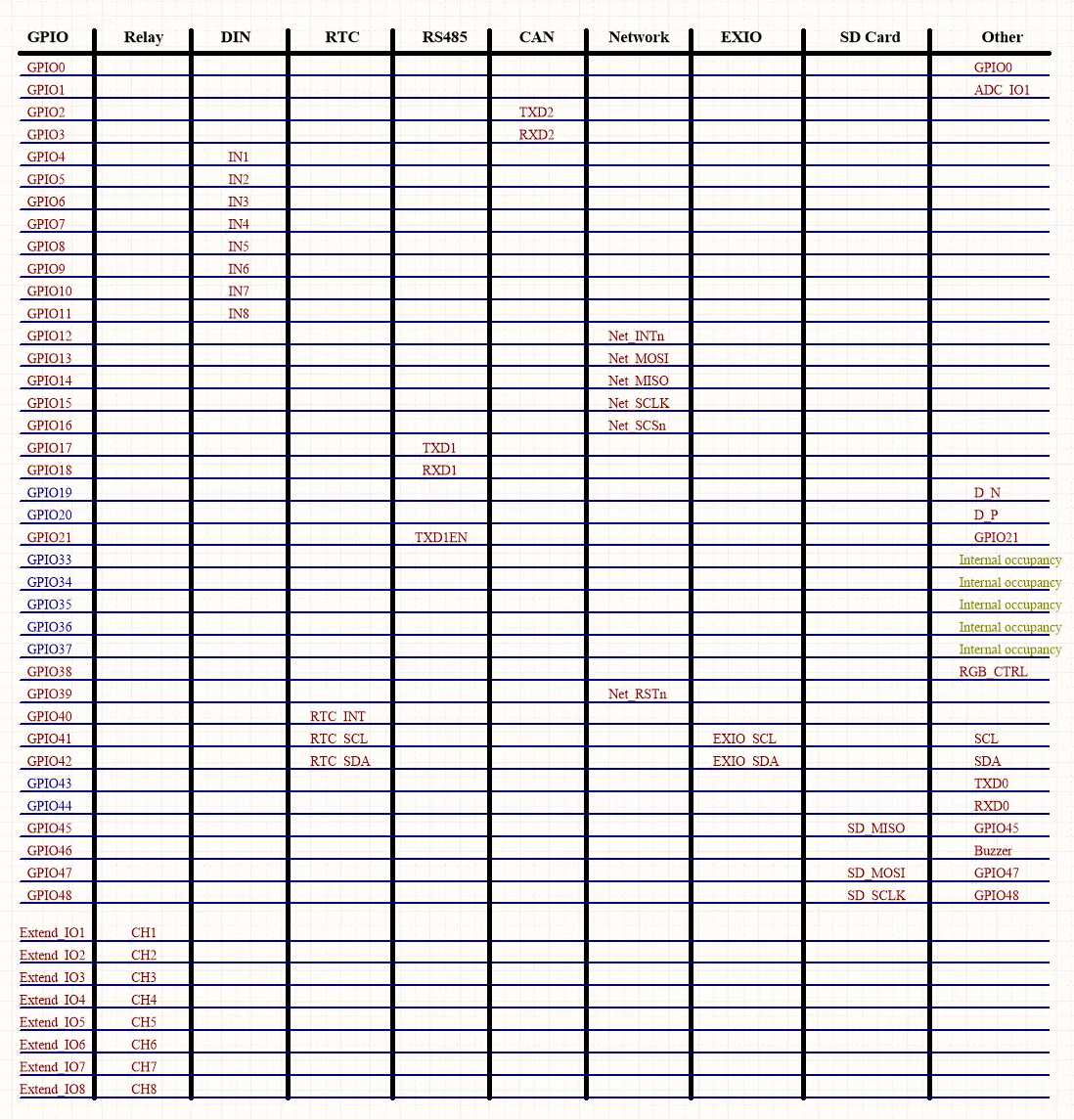
| Control EXIO | Function |
|---|
| EXIO1 | Control pin for digital output 1 |
| EXIO2 | Control pin for digital output 2 |
| EXIO3 | Control pin for digital output 3 |
| EXIO4 | Control pin for digital output 4 |
| EXIO5 | Control pin for digital output 5 |
| EXIO6 | Control pin for digital output 6 |
| EXIO7 | Control pin for digital output 7 |
| EXIO8 | Control pin for digital output 8 |
| Control GPIO | Function |
|---|
| GPIO4 | Detection pin for digital input 1 |
| GPIO5 | Detection pin for digital input 2 |
| GPIO6 | Detection pin for digital input 3 |
| GPIO7 | Detection pin for digital input 4 |
| GPIO8 | Detection pin for digital input 5 |
| GPIO9 | Detection pin for digital input 6 |
| GPIO10 | Detection pin for digital input 7 |
| GPIO11 | Detection pin for digital input 8 |
| Control GPIO | Function |
|---|
| GPIO12 | ETH_INT |
| GPIO13 | ETH_MOSI |
| GPIO14 | ETH_MISO |
| GPIO15 | ETH_SCLK |
| GPIO16 | ETH_CS |
| GPIO39 | ETH_RST |
| Control GPIO | Function |
|---|
| GPIO45 | SD_D0 |
| GPIO47 | SD_CMD |
| GPIO48 | SD_SCK |
| NC | SD_D3 |
| NC | SD_D1 |
| NC | SD_D2 |
| Control GPIO | Function |
|---|
| GPIO17 | RS485 UART TX pin |
| GPIO18 | RS485 UART RX pin |
| GPIO21 | RS485 UART RTS pin |
| Control GPIO | Function |
|---|
| GPIO2 | CAN TWAI TX pin |
| GPIO3 | CAN TWAI RX pin |
| Control GPIO | Function |
|---|
| GPIO40 | RTC_INT, interrupt pin of the RTC chip |
| GPIO41 | RTC_SCL, I2C clock line |
| GPIO42 | RTC_SDA, I2C data line |
| Control GPIO | Function |
|---|
| GPIO38 | RGB control pin |
| Control GPIO | Function |
|---|
| GPIO46 | Buzzer control pin |
| Control GPIO | Function |
|---|
| GPIO0 | BOOT button control pin |
Dimensions
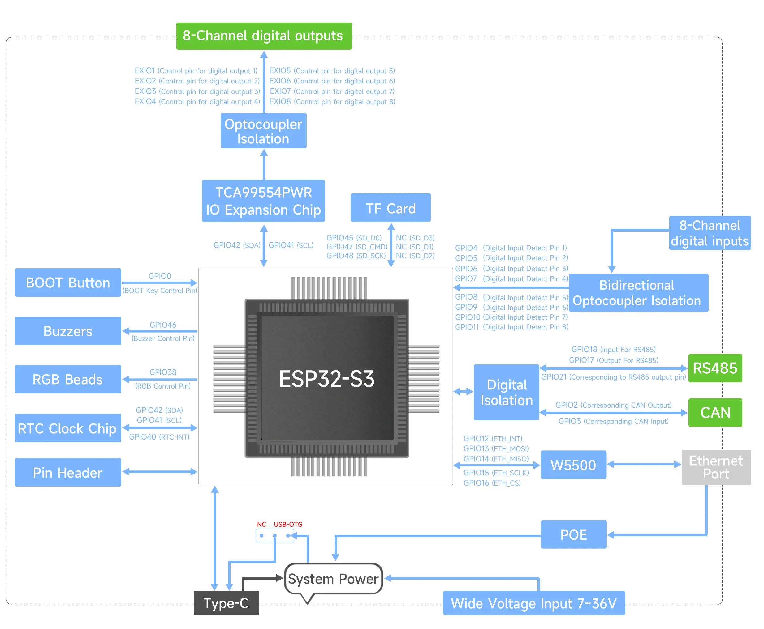
Implementation Logic
Interface Description