ESP32-S3-RGB-Matrix WLED Tutorial
This tutorial describes how to flash the WLED firmware online for the ESP32-S3-RGB-Matrix, connect to Wi-Fi, configure an HUB75 LED matrix panel, and troubleshoot common display issues.
Table of Contents
- Preparation
- Safety Precautions
- Flashing WLED Firmware Online
- Configuring the Development Board Network
- Configuring the LED Screen
- Updating WLED Firmware and Troubleshooting Color Issues
- Configuring Audio-Reactive Mode
1. Preparation
| Material | Quantity | Description |
|---|---|---|
| ESP32-S3-RGB-Matrix | 1 | Main control development board |
| RGB-Matrix-P2.5-64×32 LED matrix panel and accessories | 1 set | HUB75 interface LED matrix panel |
| Power adapter | 1 | For connecting an external 5 V power supply |
| USB data cable | 1 | For connecting the development board to the computer; do not use a cable that only supports charging |
Before starting, make sure the computer can access the internet normally, and use a browser that supports Web Serial (the latest version of Chrome or Edge is recommended).
2. Safety Precautions
- The display operates at 5 V and requires an external 5 V power supply. Do not connect any other voltage to avoid damaging the device.
Before connecting or adjusting the HUB75 ribbon cable and power cables, disconnect the power from the development board and the display to avoid hot-plugging.
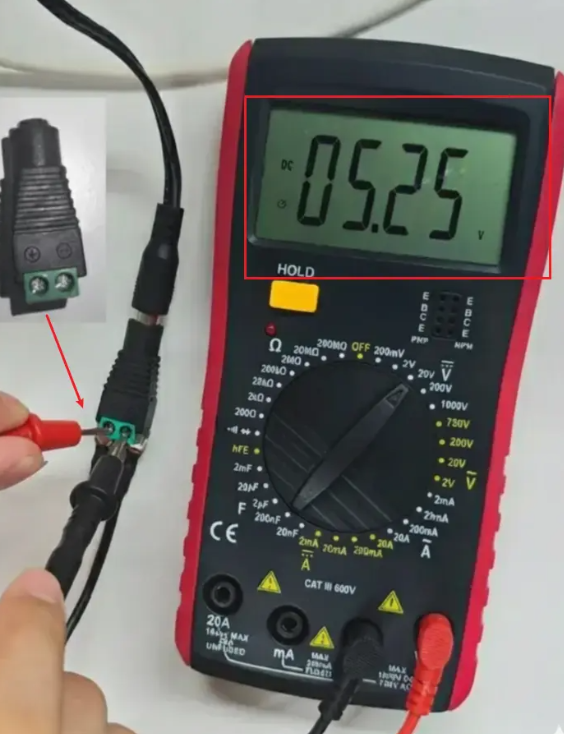
Before connecting the display, measure the output voltage of the power terminal as shown in the figure below:
- The measurement result should be +5 V.
- If you measure -5 V, it means the terminal polarity may be reversed. Stop wiring and contact customer service in time to replace the corresponding terminal.
3. Flashing WLED Firmware Online
1. Select the Firmware and Development Board
Use a browser that supports Web Serial to visit the WLED online installation page.
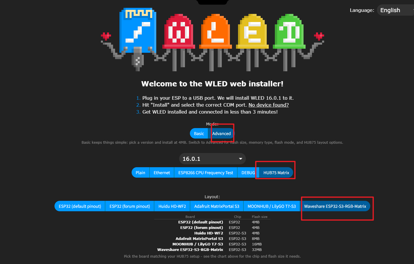
Select the installation options in the following order:
- Switch the installation mode to "Advanced".
- Select "HUB75 Matrix".
- Select "Waveshare ESP32-S3-RGB-Matrix" in "Layout".
- After confirming the selection is correct, click "Install" on the page.
2. Connect the Development Board
Connect the board to your computer using a USB cable. In the pop-up port list, select the serial port corresponding to the development board, and then click Connect.

3. Start the Installation
Select "Install WLED".

Checking "Erase device" will erase the existing data and configuration on the development board.
Check "Erase device", and then click "Next".

After confirming, click "Install".

4. Wait for Flashing to Complete
The installer will automatically erase the device and flash the firmware. This process may take a few minutes; please keep the USB connection stable and do not unplug the development board.


After flashing is complete, click "Next".

4. Configuring the Development Board Network
1. Connect to Wi-Fi
- After flashing is complete, restart the development board.
- Return to the installation page, click "Install", and reconnect the development board.
- Click "Connect to Wi-Fi".

Enter the 2.4 GHz Wi-Fi name and password, and then click "Connect".
WLED network configuration requires 2.4 GHz Wi-Fi; please make sure the network name and password are entered correctly.

2. Wait for the Connection to Complete
Wait for the development board to complete the network configuration and connect to Wi-Fi.

After the connection succeeds, click "Skip" to skip the remaining steps.

5. Configuring the LED Screen
1. Enter the WLED Configuration Page
Click "Visit Device" to open the WLED device page.

What if Visit Device does not appear?
If "Visit Device" does not appear on the page, try reconfiguring Wi-Fi:
- Open the WLED device menu.
- Click "Change Wi-Fi" and re-enter and connect to the 2.4 GHz Wi-Fi.
- After the "Device connected to the network!" prompt appears, click Continue.
- Return to the installation page and click "Visit Device" again.


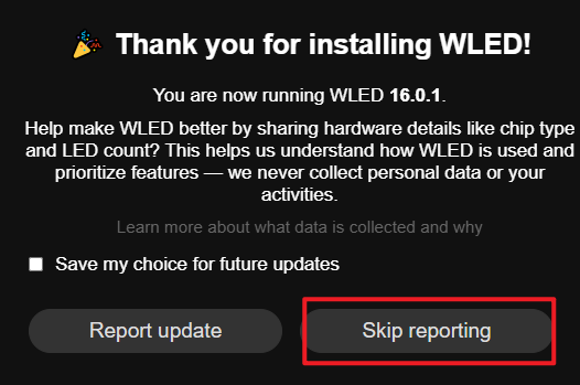
If a data reporting prompt appears, click "Skip reporting".
2. Open the LED and Hardware Settings
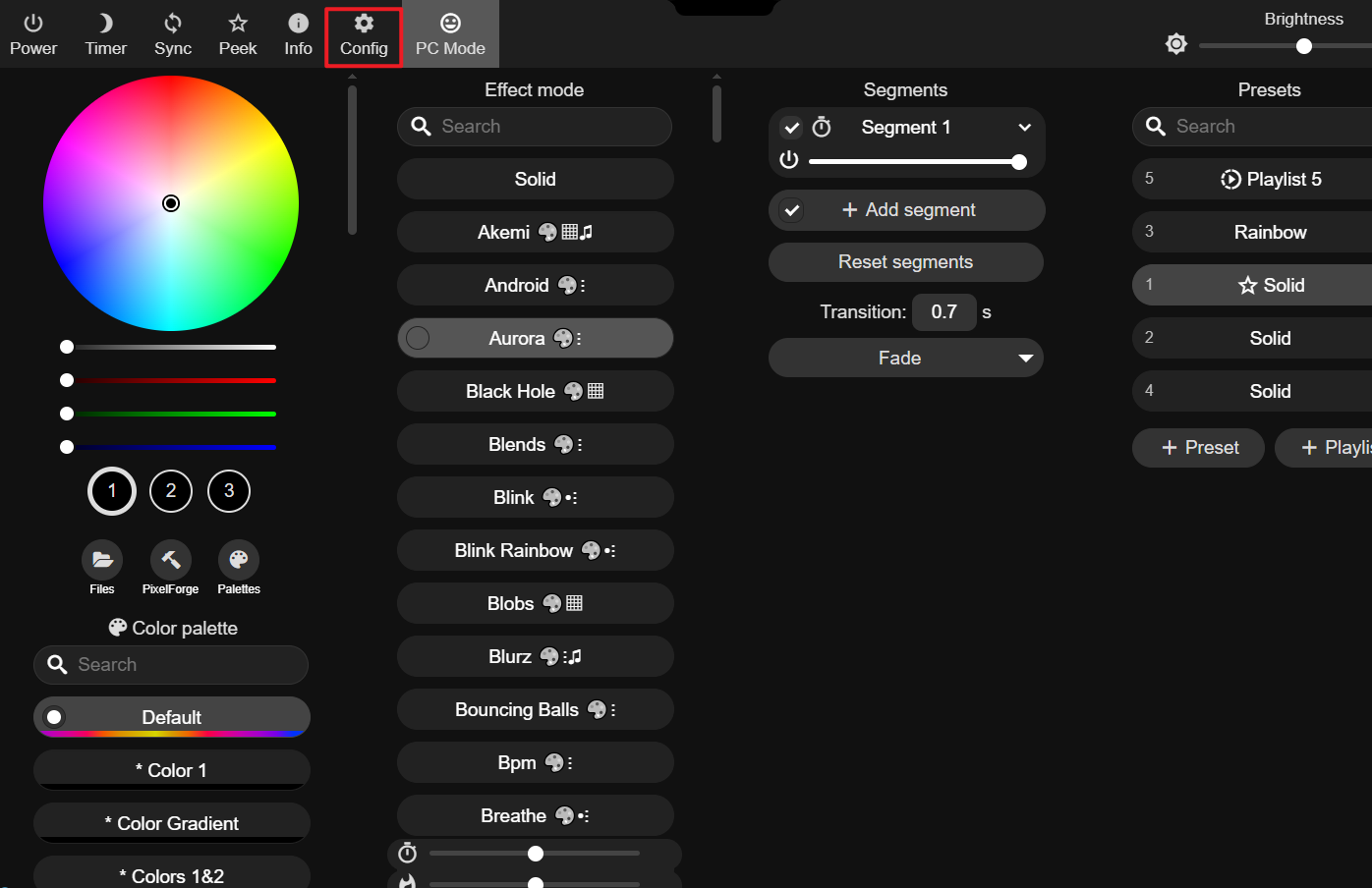
Click "Config" at the top of the WLED home page.
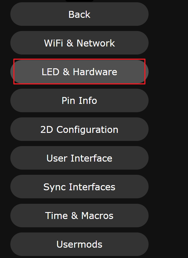
Then go to "LED & Hardware".
3. Add and Configure the LED Screen
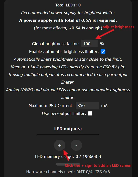
Set the brightness limit, and then click + to add an LED output.
This sets the maximum brightness the device is allowed to use. It is recommended to set a lower brightness first, and then gradually increase it after confirming the power supply and display are normal.
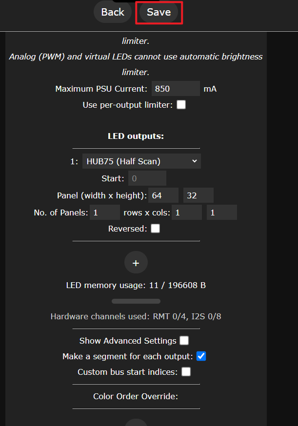
For the single P2.5 64×32 matrix panel used in this tutorial, set the parameters according to the table and screenshot below:
| Configuration Item | Setting Value |
|---|---|
| LED output type | HUB75 (Half Scan) |
| Start | 0 |
| Panel (width × height) | 64 × 32 |
| No. of Panels | 1 |
| rows × cols | 1 × 1 |
| Make a segment for each output | Checked |
If the screen size or number of tiled panels is different, adjust
Panel,rows, andcolsaccording to the actual hardware; do not simply copy the values above.

After completing the configuration, click "Save" at the top of the page to save the settings, and click "OK" in the prompt box.
4. Configure the Screen 2D Properties
Go to the "Config" page, and then select "2D Configuration".
After entering, select "2D Matrix".
Set the matrix parameters according to the actual screen dimensions.
After confirming the parameters are correct, click "Save" to save.
5. Wire Up and Restart the Device
- Click Back to return to the WLED home page.
- Disconnect the power from the development board and the LED matrix panel.
- Connect the development board, the HUB75 ribbon cable, and the external 5 V power cable of the LED matrix panel.
- Check that the power polarity, ribbon cable orientation, and connectors are correct and secure.
- After confirming the wiring is correct, power on again to start the development board and the LED matrix panel.
After modifying the HUB75 parameters and saving, you must restart WLED. The screen may temporarily go black right after the parameters are modified; the new driver configuration takes effect only after a restart.
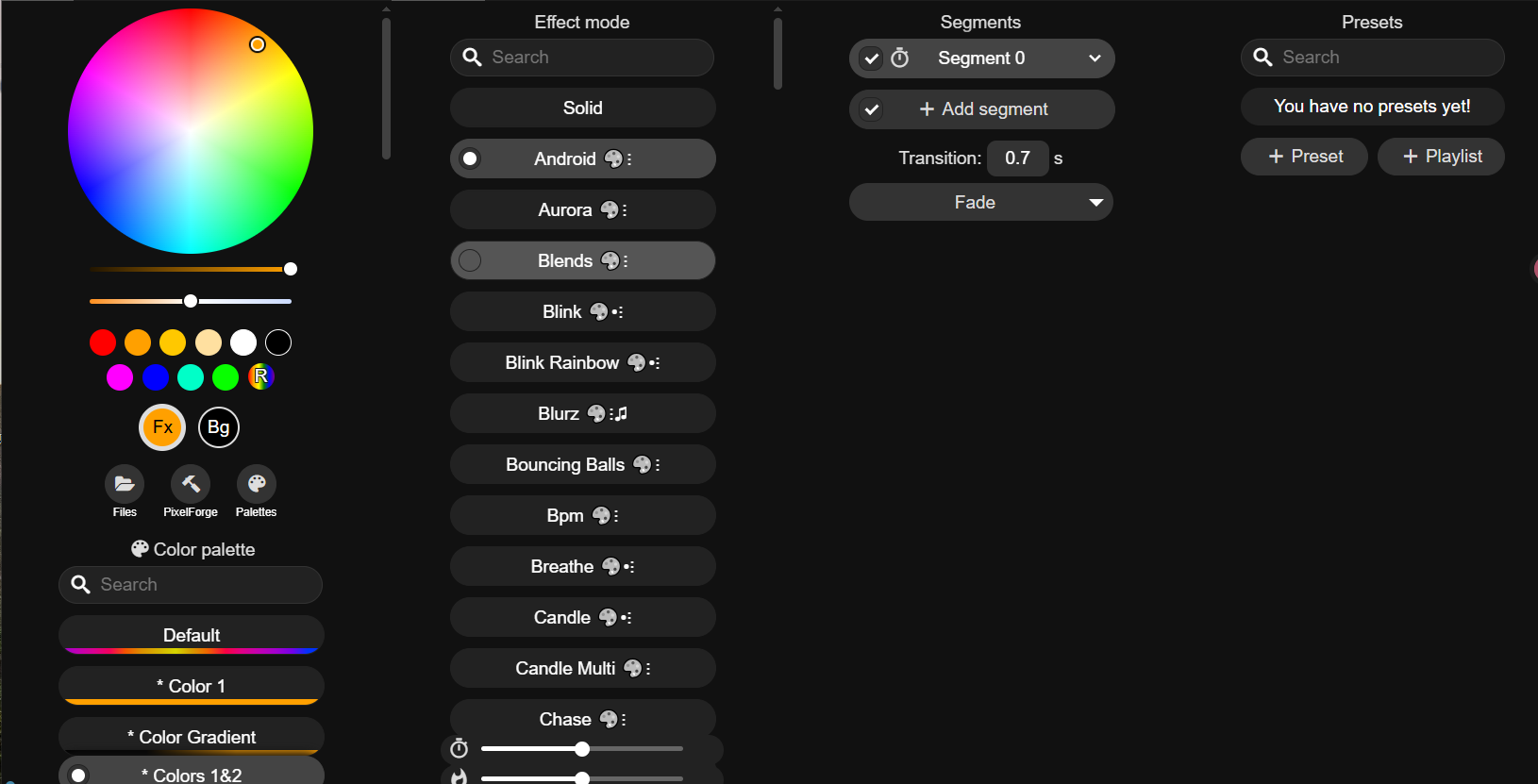
After completing the wiring and powering on again, you can adjust the brightness, color, and display effects on the WLED home page.
6. Updating WLED Firmware and Troubleshooting Color Issues
If the screen lights up but the colors do not match the colors selected on the WLED page, first check the ribbon cable orientation and the screen parameters. After confirming that the hardware connections and parameters are correct, you can try updating the matching firmware. If the current firmware lacks the audio-reactive module, you can also update it by following the steps in this section.
Only upload .bin firmware that matches the ESP32-S3-RGB-Matrix / HUB75. Uploading incorrect firmware may prevent the device from starting normally.
During the update, keep the device power and network connection stable; do not close the page, disconnect power, or restart the device.
1. Prepare the Firmware
Open the ESP32-S3-RGB-Matrix firmware directory, and download the WLED .bin firmware whose file name corresponds to the model and size of the LED matrix panel in use. The test firmware and Xiaozhi firmware in this directory are not applicable to the WLED update in this section.
Only the RGB-Matrix-Px-96x48 panel needs to be flashed with the V2 firmware.
2. Open the Software Update Page
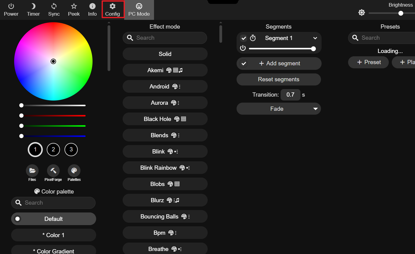
Click "Config" at the top of the WLED home page.
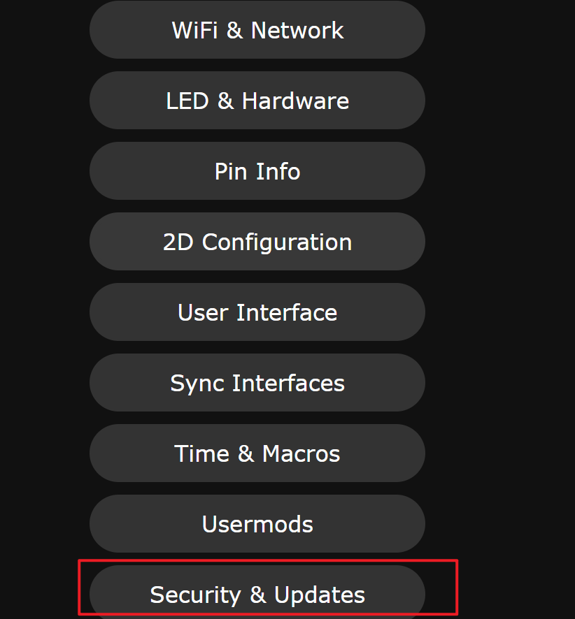
Click "Security & Updates" in the configuration menu.
Find "Software Update", and then click "Update WLED".

3. Manually Upload the Firmware
In the "Manual upload" area, click "Choose File" and select the downloaded WLED .bin firmware.
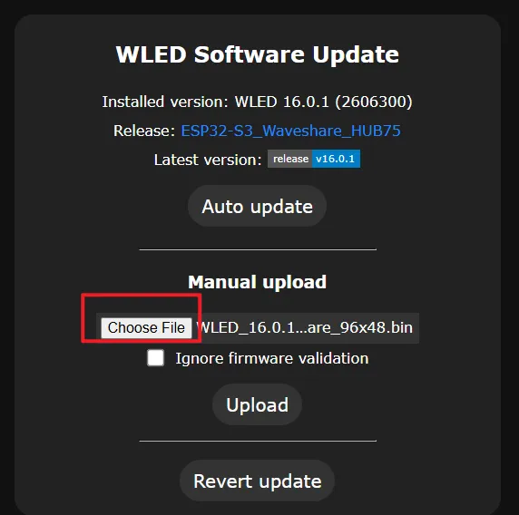
After confirming the file is correct, click "Upload" to start the update.
It is usually not necessary to check "Ignore firmware validation". Unless the firmware provider explicitly requires it, keep this option unchecked.
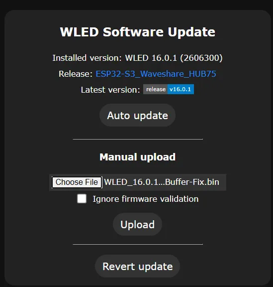
Wait for the firmware upload and device restart to complete. After the page automatically returns to the WLED home page, refresh the web page, and then test whether the screen colors have returned to normal.
7. Configuring Audio-Reactive Mode
The ESP32-S3-RGB-Matrix has an onboard ES7210, ES8311, and dual microphones. The audio-reactive function requires the Waveshare HUB75 dedicated firmware that includes the AudioReactive usermod.
1. Confirm That the Firmware Supports AudioReactive
Open the WLED "Info" page and confirm that the firmware name is:
ESP32-S3_Waveshare_HUB75
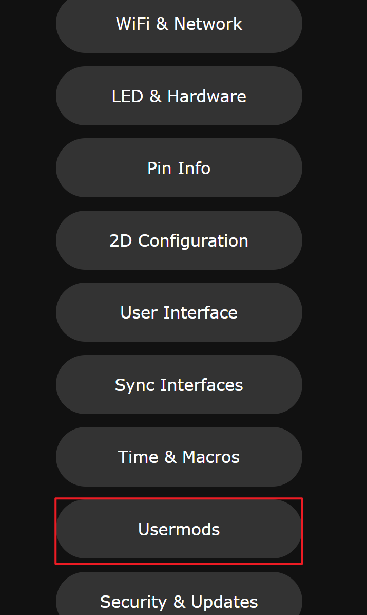
Then go to "Config" > "Usermods".
If "AudioReactive" does not appear on the page, it means the current firmware does not include the audio-reactive module. Please first update the WLED firmware applicable to this development board according to the steps in Updating WLED Firmware and Troubleshooting Color Issues.
2. Set Up the Onboard Microphone
Configure the following in the "AudioReactive" area according to the table below:
| Configuration Item | Setting Value |
|---|---|
| Enabled | Checked |
| Digitalmic Type | ES8311 |
| I2S SD | 39 |
| I2S WS | 38 |
| I2S SCK | 43 |
| I2S MCLK | 12 |
| I2C SDA | unused |
| I2C SCL | unused |
| Squelch | 10 |
| Gain | It is recommended to start from 60, and gradually increase to 120 if the response is weak |
| AGC | Normal |
| Sync Mode | Select Off for standalone use |
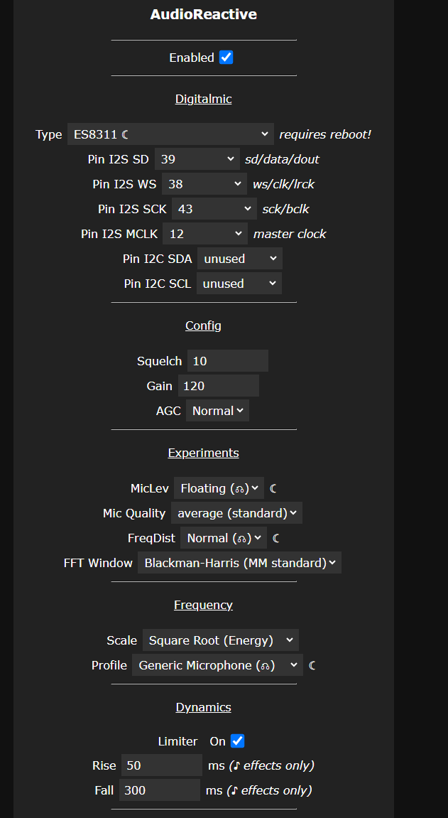

After the settings are complete, save and power on again according to the following steps:
- Click "Save".
- Unplug the USB and other power supplies from the development board.
- Wait about 2 seconds, then power on again.
After modifying the microphone type or audio pins, perform a complete power cycle. The ES8311/ES7210 may sometimes retain register states, and restarting only through the web page may not fully reset the audio chip.
3. Check the Audio Module Status
After powering on again, open the "Info" page and check "Audio Source" and "Sound Processing". Under normal conditions, the audio source is initialized and sound processing is running.
If you see the following information, it means the audio driver did not start successfully:
Audio Source: not initialized - check pin settings
Sound Processing: suspended
If this state occurs, recheck the microphone type and pins in the table above, then save again and perform a complete power cycle.
4. Test the Audio-Reactive Effect
- Return to the WLED main interface.
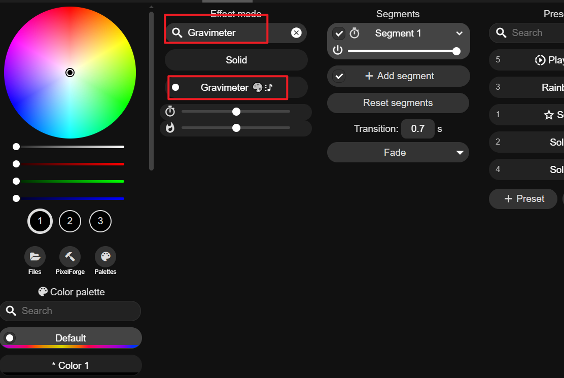
- Open "Effects mode".
- Select an audio-responsive effect, such as
GEQ,Gravimeter,Freqwave, orWaterfall. - Clap in front of the onboard microphone, or play music near the development board.
- Observe whether the LED matrix pattern changes with the sound intensity and frequency.
If the response is weak, gradually increase "Gain"; if the pattern keeps jumping even in a quiet environment, increase "Squelch".
5. Audio Synchronization
For standalone use, set "Sync Mode" to Off. If you need two WLED devices to use the same audio source:
- Set the device with the microphone to
Send; - Set the other device to
Receive; - Connect both devices to the same local area network;
- Use the same audio sync port on both devices; the default port is
11988.
Complete
At this point, the WLED firmware flashing, network connection, and LED matrix panel configuration are all complete. If the screen does not display properly, please check the following items first:
- Whether the external power supply provides a stable 5 V output;
- Whether the positive and negative poles of the power supply are connected correctly;
- Whether the HUB75 ribbon cable orientation is correct and whether the connectors are firmly inserted;
- Whether the LED screen parameters match the figure above;
- Whether the development board has been restarted after saving the HUB75 parameters;
- Whether the WLED web page has been refreshed after restarting the development board;
- If color issues occur, whether it has been confirmed that the firmware matches the development board model.