ESP32-S3-Relay-6CH
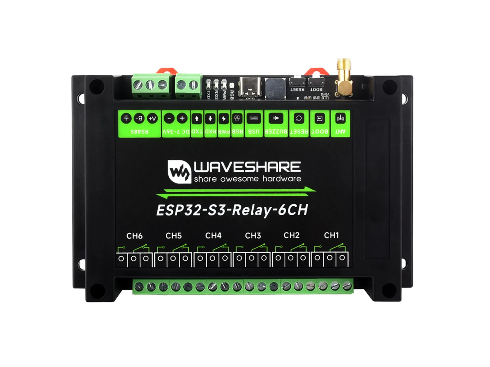
ESP32-S3-Relay-6CH is an industrial-grade 6-channel Wi-Fi network relay based on the ESP32-S3 main controller, supporting Wi-Fi, Bluetooth, RS485, Pico, and other peripheral interfaces. It features built-in power isolation, optocoupler isolation, and other protection circuits, making it safe, stable, and reliable for AIoT applications.
If you are looking for:
- Coding with AI tools: Click Ask AI and select an AI tool to ask questions about this page, or choose Copy page to copy its content and paste it into an AI tool for coding assistance.
- Schematics, datasheets, and example code: See Resources
- Factory firmware: See Firmware Flashing and Erasing
- Arduino development: See Working with Arduino
- MicroPython development: See Working with MicroPython
- Troubleshooting: See Product FAQ or contact Technical Support
| SKU | Product |
|---|---|
| 26756 | ESP32-S3-Relay-6CH |
Features
- Based on the ESP32-S3 microcontroller, equipped with an Xtensa 32-bit LX7 dual-core processor running at up to 240MHz
- Integrated 2.4GHz Wi-Fi and Bluetooth LE dual-mode wireless communication with excellent RF performance
- Uses high-quality relays, allowing load connection: ≤10A 250V AC or ≤10A 30V DC
- Onboard isolated RS485 interface, convenient for expanding and connecting various RS485 Modbus industrial expansion modules or sensors
- Onboard Pico-compatible interface, compatible with some Raspberry Pi Pico expansion boards, convenient for expanding RTC / CAN / RS232 / LoRa / sensors and other functions
- Onboard USB Type-C interface, can be used for power supply and download/debugging, convenient for development
- Onboard power supply screw terminal, supports 7~36V wide voltage input, suitable for industrial applications
- Onboard optocoupler isolation to prevent interference with control chip from external high-voltage circuit connected to the relay
- Onboard digital isolation to avoid external signal interference with the control chip
- Onboard integrated isolated power supply provides stable isolated voltage; the isolated side requires no additional power
- Built-in buzzer, RGB colorful LED, power supply and RS485 TX/RX indicators for monitoring the operating status of the module
- Rail-mounted ABS protective enclosure, easy to install, safe to use
Specifications
| Parameter | Value |
|---|---|
| Supply Voltage | 7-36V (or 5V/1A Type-C interface) |
| Number of Relay Channels | 6 channels |
| Contact Type | One normally open, one normally closed |
| Wiring Port | Type-C |
| Communication Protocol | USB protocol |
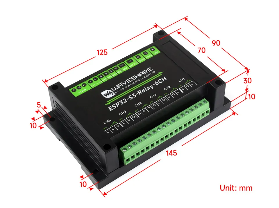
| Product Dimensions | 88 (H) x 122 (V) mm |
Onboard Resources
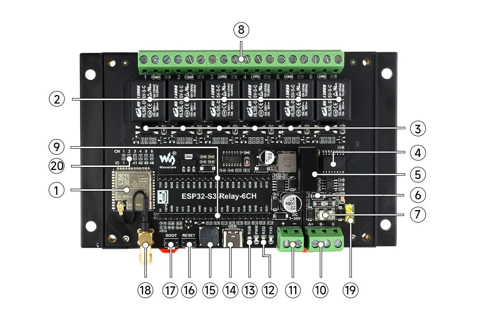
- ESP32-S3 Up to 240MHz, equipped with 2.4GHz Wi-Fi and Bluetooth Low Energy
- High-quality relay Single relay allows load connection: ≤10A 250V AC or ≤10A 30V DC
- Optocoupler isolation Prevents high-voltage circuits connected to the relay from interfering with the control chip
- Digital isolation Prevents external signals from interfering with the control chip
- Power isolation Provides stable isolation voltage, no additional power supply required on the isolated side
- TVS diode (Transient Voltage Suppressor) Effectively suppresses surge voltage and transient spike voltage in the circuit
- Ceramic gas discharge tube
- Relay screw terminals Convenient for users to connect devices
- Raspberry Pi Pico HAT header Can connect to Raspberry Pi Pico expansion boards
- RS485 communication interface Supports connecting external RS485 devices
- Power supply screw terminal Supports DC 7~36V wide voltage input
- LED indicators PWR: Power indicator RXD: RS485 receive indicator TXD: RS485 transmit indicator
- WS2812 RGB LED Can be controlled via GPIO38 pin
- USB Type-C interface Can be used for device power supply, firmware download, and USB communication
- Passive buzzer Sound frequency can be controlled via GPIO21 pin
- ESP32 RESET button
- ESP32 BOOT button
- External antenna connector SMA female connector, for Wi-Fi and Bluetooth wireless communication
- RS485 matching resistor Reserved 120R matching resistor, can be enabled with jumper cap
- Relays default control pin setting
Interface Introduction
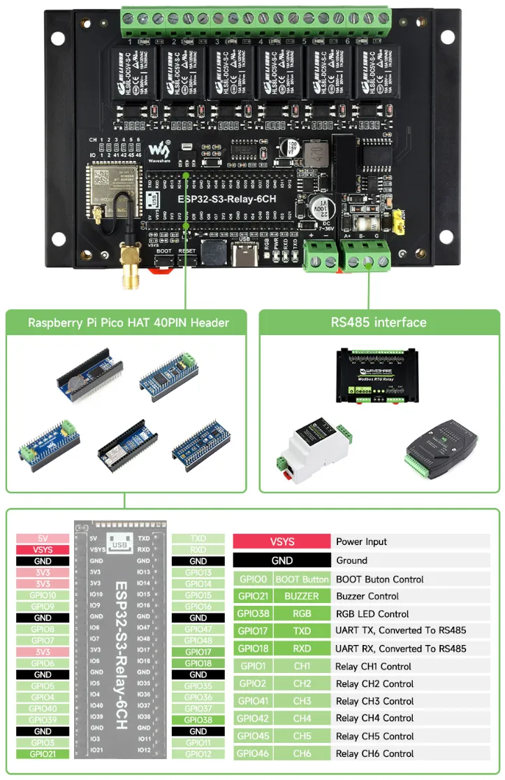
| Control GPIO | Function | Description |
|---|---|---|
| GP0 | BOOT Button | BOOT button control pin |
| GP21 | BUZZER | Buzzer control pin |
| GP38 | RGB | RGB LED control pin |
| GP1 | CH1 | Relay 1 control pin |
| GP2 | CH2 | Relay 2 control pin |
| GP41 | CH3 | Relay 3 control pin |
| GP42 | CH4 | Relay 4 control pin |
| GP45 | CH5 | Relay 5 control pin |
| GP46 | CH6 | Relay 6 control pin |
| GP17 | TXD | RS485 UART TX pin |
| GP18 | RXD | RS485 UART RX pin |
Dimensions
Electrical Safety and Relay Precautions
- This product must be used by professional electricians or technical personnel. Please take appropriate electrical safety, leakage prevention, and insulation measures during use.
- Before installing, maintaining, or replacing relay equipment, be sure to turn off the power and unplug the connector.
- Do not attempt to disassemble the relay equipment to avoid damage or electric shock.
- Install and place the relay product properly. Do not use it in humid, overheated, flammable, or explosive environments to avoid safety accidents caused by improper installation or use.
1. Load Matching
- Ensure that the rated voltage and current of the relay match the load. Do not overload. Excessive current may cause contact melting, sticking, or even fire.
- For inductive loads (motors, coils, lamps, etc.), the inrush current may be much higher than the rated current. Select a relay with sufficient margin for the rated current.
2. Short Circuit and Overcurrent Protection
- Add a fuse or air switch (circuit breaker) to the relay circuit to prevent load short circuits or accidental overcurrent from burning out the relay.
- Ensure no short circuit in the load circuit during wiring, and use protection components with appropriate current ratings if necessary.
3. Arc and Pull-in Protection
- Arcing occurs at the moment of relay switching, which can easily cause contact wear or welding.
- It is recommended to use RC snubber circuits or varistors and other arc suppression protection for inductive loads.
4. Installation Environment
- Avoid using in humid, high-temperature, flammable, explosive, or dusty environments.
- Mount the relay securely to prevent false operation or damage due to vibration or impact.
5. Power Off Operation
- Before maintenance, wiring, or relay replacement, be sure to disconnect power to ensure personal and equipment safety.
- Latching relays are energized only when changing state and are normally de-energized. Avoid strong vibration or magnetic field interference that could alter the relay state.
6. State Confirmation
- After powering on, confirm or reset the relay state as needed to avoid abnormal operation due to transportation, installation, or external interference.
- Avoid cutting power during latching relay operation to prevent undefined states or contact damage.
7. Regular Inspection
- After long-term use, regularly inspect the relay contacts, terminals, and insulation to ensure normal operation.
- If abnormal heating, odor, or burn marks appear, immediately disconnect power and replace the relay.