ESP32-S3-Relay-6CH Working with Arduino
This chapter includes the following sections. Please read as needed:
Arduino Getting Started
New to Arduino ESP32 development and looking for a quick start? We have prepared a comprehensive Getting Started Tutorial for you.
- Section 0: Getting to Know ESP32
- Section 1: Installing and Configuring Arduino IDE
- Section 2: Arduino Basics
- Section 3: Digital Output/Input
- Section 4: Analog Input
- Section 5: Pulse Width Modulation (PWM)
- Section 6: Serial Communication (UART)
- Section 7: I2C Communication
- Section 8: SPI Communication
- Section 9: Wi-Fi Basics
- Section 10: Web Server
- Section 11: Bluetooth
- Section 12: LVGL GUI Development
- Section 13: Comprehensive Project
Note: This tutorial uses the ESP32-S3-Zero as a reference example, and all hardware code is based on its pinout. Before you start, we recommend checking the pinout of your development board to ensure the pin configuration is correct.
Setting Up the Development Environment
1. Install and Configure Arduino IDE
Please refer to the tutorial Install and Configure Arduino IDE to download and install the Arduino IDE and add ESP32 support.
- Board installation instructions for ESP32-S3-Relay-6CH
| Board Name | Board Installation Requirement | Version Requirement |
|---|---|---|
| esp32 by Espressif Systems | "Offline installation" / "Online installation" | 2.0.12 |
2. Installing Libraries
- When installing Arduino libraries, there are typically two options: Online Installation and Offline Installation. If the library installation requires offline installation, you must use the provided library files.
For most libraries, users can easily search and install them via the Arduino software's built-in Library Manager. However, some open-source or custom libraries are not synchronized to the Arduino Library Manager, so they cannot be found through online search. In this case, you can only install these libraries manually offline. - For a library installation tutorial, see the library installation section in the Install and Configure Arduino IDE.
- The ESP32-S3-Relay-6CH library files are stored in the example program. Click here to go to: ESP32-S3-Relay-6CH Example.
- Library installation instructions for ESP32-S3-Relay-6CH
| Library Name | Description | Version | Library Installation Requirement |
|---|---|---|---|
| ArduinoJson | Lightweight JSON library | v6.21.4 | Online or offline installation |
| PubSubClient | MQTT message publish/subscribe library | v2.8.0 | Online or offline installation |
| NTPClient | Network time synchronization client library | v3.2.1 | Online or offline installation |
For more LVGL learning and usage, refer to the LVGL Official Documentation.
Example

ESP32-S3-Relay-6CH Example Programs
| Example | Basic Description | Dependency Library |
|---|---|---|
| 01_MAIN_WIFI_AP | RS485 interface control, Bluetooth control, Bluetooth IP transmission, Web page control (short range) | Can be flashed directly. The Web page can only be used when connected to the device's Wi-Fi |
| 02_MAIN_WIFI_STA | RS485 interface control, Bluetooth control, Bluetooth IP transmission, Web page control (short range) | Requires modifying the Wi-Fi to connect to. The Web page is for intranet use only |
| 03_MAIN_WIFI_MQTT | RS485 interface control, Bluetooth control, Bluetooth IP transmission, Waveshare Cloud control (long range) | Requires modifying the Wi-Fi to connect to. A device must be created in Waveshare Cloud. (Note: Waveshare Cloud is no longer maintained. Please choose another cloud service.) |
| 04_MAIN_ALL | RS485 interface control, Bluetooth control, Bluetooth IP transmission, Web page control (short range), Waveshare Cloud control (long range) | Requires modifying the Wi-Fi to connect to. A device must be created in Waveshare Cloud. The Web page is for intranet use only. (Note: Waveshare Cloud is no longer maintained. Please choose another cloud service.) |
Arduino Project Settings
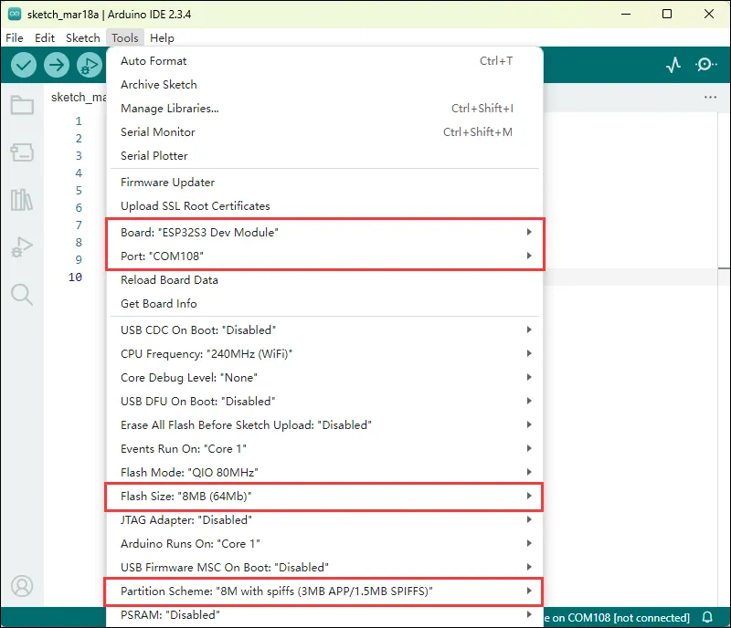
01_MAIN_WIFI_AP
Example Description
- This example implements controlling the switches of 6 relays via Wi-Fi, Bluetooth, and RS485. This example enables the Wi-Fi AP mode.
Note
- Can be flashed directly.
- The Web page can only be used when connected to the device's Wi-Fi.
Code Analysis
-
Relay_Analysis(): This function is mainly used to analyze the received data and, based on the data content, execute the corresponding relay control operations and output the corresponding status prompt information.
- Parameter Analysis
uint8_t *buf: A pointer to an unsigned 8-bit integer array. This array should store the received data. The function determines the specific command content based on the value of the first element of the array (buf[0]).uint8_t Mode_Flag: A mode flag indicating the data source. By checking this flag, it outputs the corresponding data source prompt information (such as Bluetooth data, Wi-Fi data, or RS485 data), and performs different relay operations according to different commands.
- Logic Flow
- First, output the corresponding data source prompt information based on the value of
Mode_Flag. - Then, use a
switchstatement to execute different operations based on the value ofbuf[0]:- For cases
CH1toCH6, use thedigitalTogglefunction to toggle the level state of the corresponding GPIO pin (such asGPIO_PIN_CH1, etc.), update the correspondingRelay_Flagarray element to record the change in relay state, call theBuzzer_PWMfunction to control the buzzer, and output the corresponding on or off prompt information based on the final relay state. - For the
ALL_ONcommand, set all GPIO pins (corresponding to the 6-channel relays) to high level (on state), use thememsetfunction to set all elements of theRelay_Flagarray to 1, indicating that all relays are on, output a prompt that all relays are on, and control the buzzer. - For the
ALL_OFFcommand, similarly set all relevant GPIO pins to low level (off state), update theRelay_Flagarray elements to 0, output a prompt that all relays are off, and control the buzzer, with two additional buzzer control operations (with a delay in between). - If the value of
buf[0]does not match the above command cases, output a prompt indicating that non-command data was received.
- For cases
- First, output the corresponding data source prompt information based on the value of
- Parameter Analysis
-
WIFI_Init (): Configures the device as a Wi-Fi access point (AP), sets up a Web server, and sets request handler functions for different paths, implementing relevant network functions and device control functions, while providing corresponding status prompts.
- AP Creation
- First set the Wi-Fi mode to
WIFI_AP, then attempt to create a soft AP viaWiFi.softAP(ssid, password). If it fails, it will loop with a prompt and retry until successful.
- First set the Wi-Fi mode to
- Parameter Configuration and Prompts
- After successfully creating the AP, provide a prompt using the RGB LED (green light for 1 second).
- IP Address Display
- Get and format the soft AP's IP address, store it in
ipStr, and output it for display, making it easy to know the network address.
- Get and format the soft AP's IP address, store it in
- Web Server Setup
- Use
server.onto set corresponding request handler functions (such ashandleRoot,handleGetData, etc.) for multiple paths (such as "/", "/getData", etc.). Each function should be defined elsewhere for different functional operations, such as returning pages, getting data, controlling switches, etc. - Finally, call
server.begin()to start the Web server and output a startup prompt.
- Use
- AP Creation
RS485 Control
Use an RS485 device to connect to the ESP32-S3-Relay-6CH device. Sending data to the ESP32-S3-Relay-6CH can control the opening and closing of each relay. Communication is performed at a default baud rate of 9600.
| Operation Command | Command Function |
|---|---|
| 06 05 00 01 55 00 A2 ED | Toggle CH1 relay state |
| 06 05 00 02 55 00 52 ED | Toggle CH2 relay state |
| 06 05 00 03 55 00 03 2D | Toggle CH3 relay state |
| 06 05 00 04 55 00 B2 EC | Toggle CH4 relay state |
| 06 05 00 05 55 00 E3 2C | Toggle CH5 relay state |
| 06 05 00 06 55 00 13 2C | Toggle CH6 relay state |
| 06 05 00 FF FF 00 BD BD | Turn on all relays |
| 06 05 00 FF 00 00 FC 4D | Turn off all relays |
- Hardware Connection
The example uses a USB TO RS232/485 Converter for demonstration.
| ESP32-S3-Relay-6CH | USB-TO-RS232-485 |
|---|---|
| RS485 - A+ | Tx B - A+ |
| RS485 - B- | Rx B - B- |
-
Software Operation
-
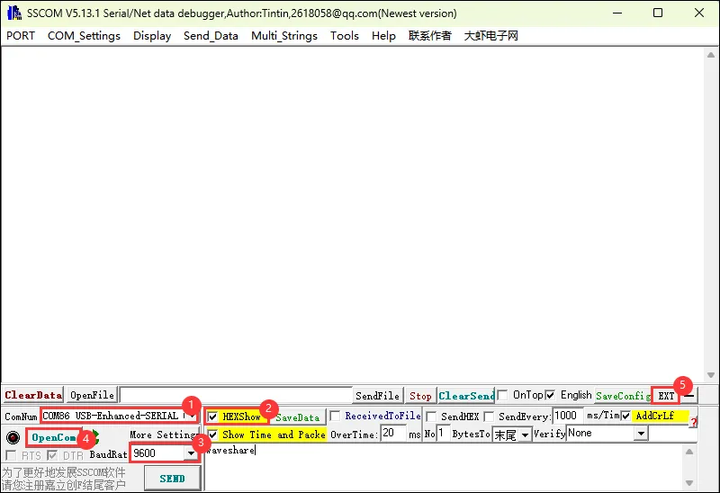
Use SSCOM for data sending
-
Open the SSCOM software and select the COM port corresponding to the Port B connected above.
-
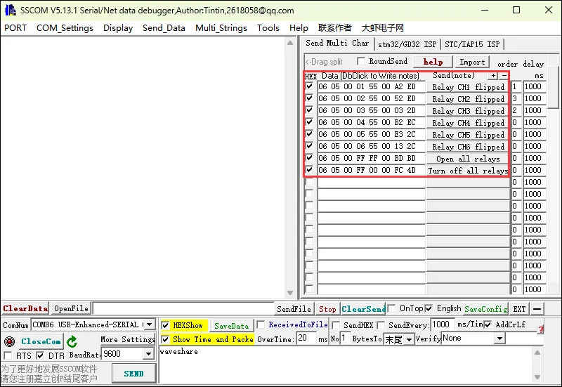
Open the serial port and use the multi-send function to quickly send commands
-
-
The following commands can be used for relay control.
Bluetooth Control
Use a mobile Bluetooth debug assistant to connect to the ESP32-S3-Relay-6CH device. Sending data to the ESP32-S3-Relay-6CH can control the opening and closing of each relay. Please note: some Bluetooth debug assistants send data in ASCII format by default. Before controlling the device, you need to enter the correct control commands according to the Bluetooth debug assistant.
| ASCII | Hex | Command Function |
|---|---|---|
| 1 | 0x31 | Toggle CH1 relay state |
| 2 | 0x32 | Toggle CH2 relay state |
| 3 | 0x33 | Toggle CH3 relay state |
| 4 | 0x34 | Toggle CH4 relay state |
| 5 | 0x35 | Toggle CH5 relay state |
| 6 | 0x36 | Toggle CH6 relay state |
| 7 | 0x37 | Turn on all relays |
| 8 | 0x38 | Turn off all relays |
- Software Operation (View IP)
- Use the mobile Bluetooth debug assistant nRF Connect for relay control (other Bluetooth debug assistants can also be used).
- The following uses nRF Connect for functional demonstration.
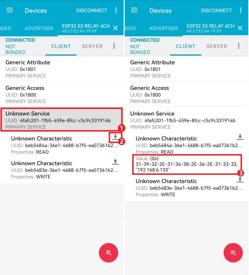
- Connect to the Bluetooth device named ESP32 S3 Relay 6CH.
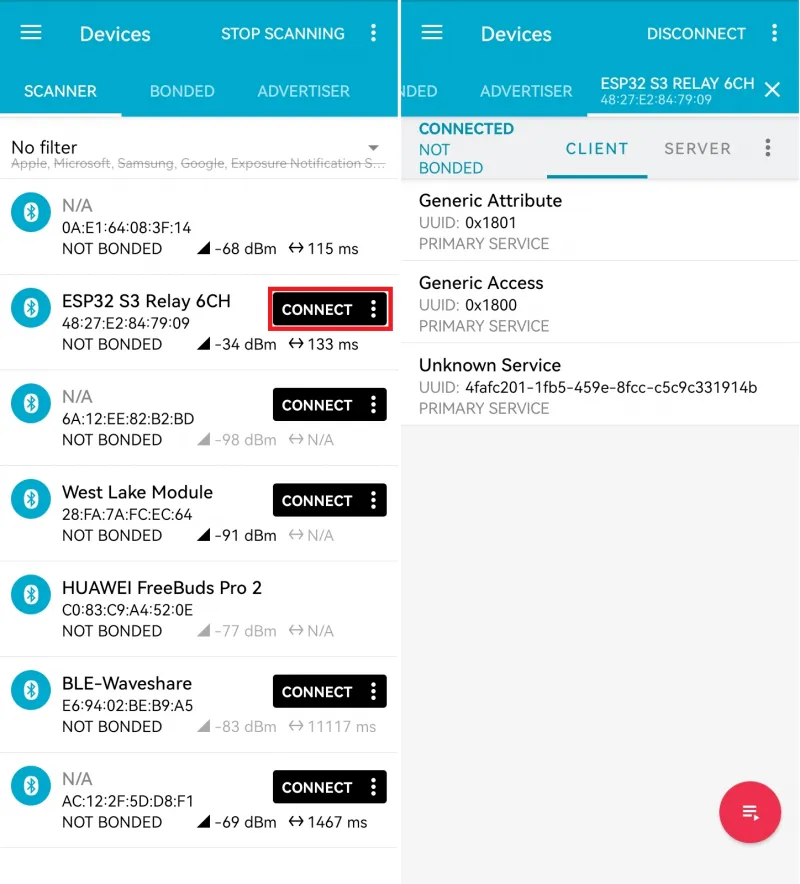
- After successful connection, select Unknown Service, click to read data. If Wi-Fi connection fails for a long time, the RGB will stay red, and this operation will have no response.
- When Wi-Fi is successfully connected, the device IP will be received as follows. The device IP is 192.168.6.133.
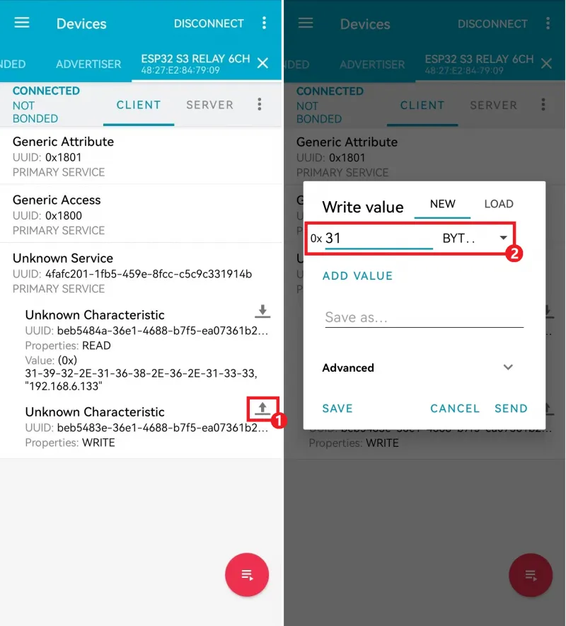
- The Bluetooth relay control commands are characters 1-8, i.e., hexadecimal 0x31 - 0x38.
- Click the send button, select the hexadecimal BYTE data type, and enter
31to send the CH1 toggle command.
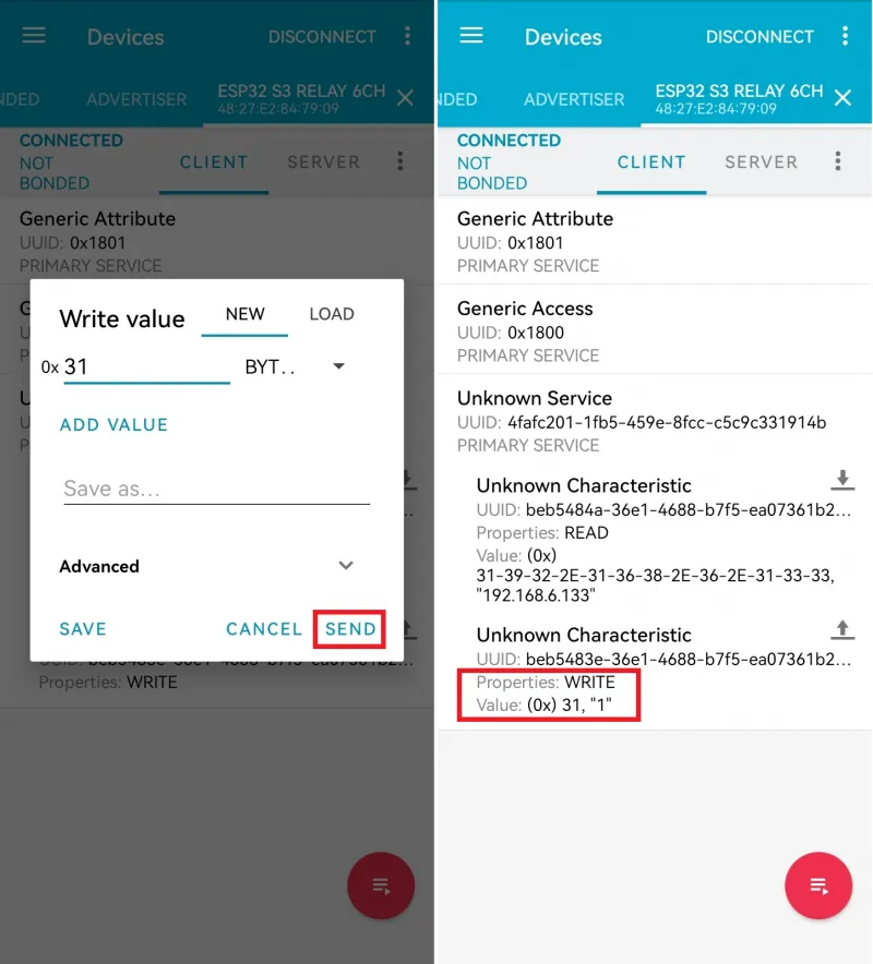
- Sending 0x31 can control relay CH1 to toggle its state.
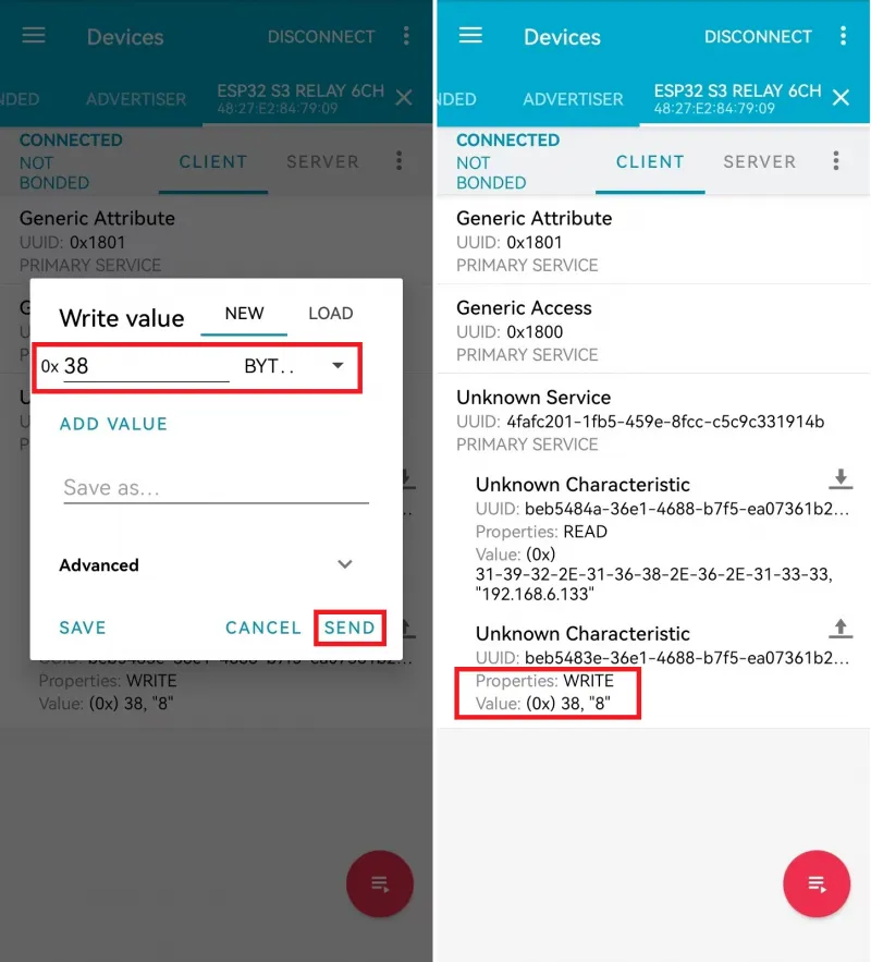
- Sending 0x38 can control turning off all relays.
Web Page Control
Use a mobile Bluetooth debug assistant to connect to the ESP32-S3-Relay-6CH device, obtain the IP after connecting to Wi-Fi, and open the Web page via the IP.
-
AP Mode
- Connect to the Wi-Fi of the ESP32-S3-Relay-6CH device. The Wi-Fi name is ESP32-S3-Relay-6CH, and the password is waveshare.
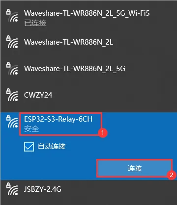
- Obtain the current IP through the Bluetooth debug assistant.
- Open the Web page to control the relays. (After the device is powered on, it takes a short time to configure. The first time the Web page is opened after each power-on may be slow.)
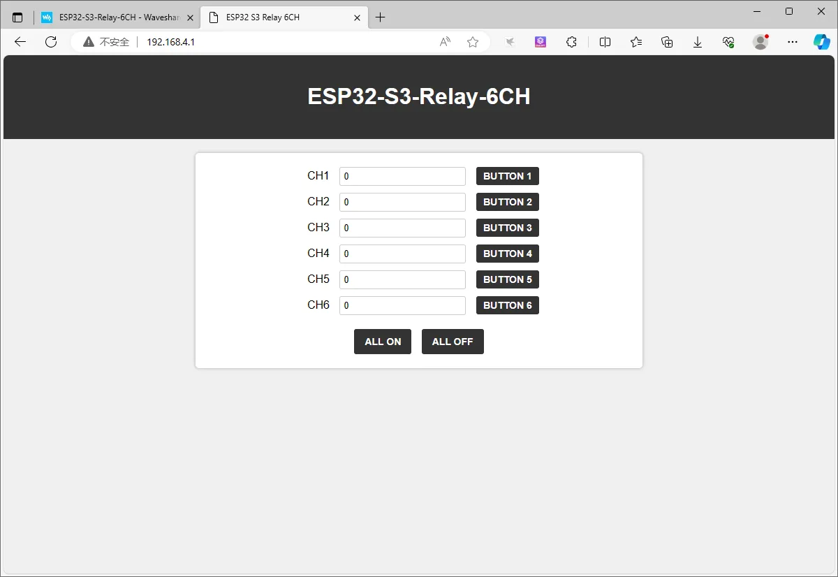
-
STA Mode
- After the device is powered on, it will automatically connect to the configured Wi-Fi (modify the Wi-Fi to connect to before flashing the program).
- Obtain the current IP through the Bluetooth debug assistant.
- Open the Web page to control the relays. (After the device is powered on, it takes a short time to configure. The first time the Web page is opened after each power-on may be slow.)
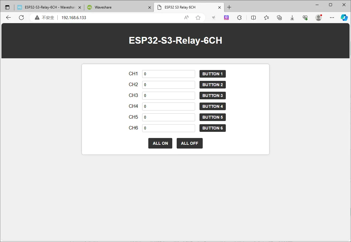
02_MAIN_WIFI_STA
Example Description
- This example implements controlling the switches of 6 relays via Wi-Fi, Bluetooth, and RS485. This example enables the Wi-Fi STA mode.
Note
- Requires modifying the Wi-Fi to connect to.
- The Web page only supports controlling the device when it is on the same network as this product. If using a mobile phone for control, mobile data must be turned off.
Code Analysis
- WIFI_Init (): Makes the device connect to the specified Wi-Fi network in station (STA) mode. If the connection is successful, it performs subsequent network-related configurations (such as obtaining the IP address, starting the Web server, and registering callback functions, etc.). If the connection fails, it provides a corresponding prompt and sets the connection status flag. During the process, it also provides visual prompts of the connection status via the RGB LED.
- Wi-Fi Network Connection Attempts:
- First set Wi-Fi to
WIFI_STAmode and enable sleep mode, then start connecting to the specified network. During the loop waiting for a successful connection, output a dot as a prompt every half second. On every even-numbered attempt (except the first), briefly light the RGB LED red as a prompt. After every 10 failed attempts, disconnect and reconnect. If the number of attempts exceeds 22, consider the connection failed and exit the loop.
- First set Wi-Fi to
- Operations After Successful Connection:
- If the number of connection attempts is less than 23 (i.e., connection successful), set
WIFI_Connectionto 1, light the green LED for 1 second as a success prompt, then obtain and display the local IP address. Next, register callback functions for multiple paths with the Web server (such as the root path, get data, control different switches, etc.). Finally, start the server and output a startup prompt, enabling the device to accept corresponding control through the web page.
- If the number of connection attempts is less than 23 (i.e., connection successful), set
- Operations After Connection Failure:
- If the number of attempts is greater than or equal to 23 (connection failed), set
WIFI_Connectionto 0, output a prompt informing that the device can be controlled via a Bluetooth debug assistant, and light the red LED to indicate the connection failure status.
- If the number of attempts is greater than or equal to 23 (connection failed), set
- Wi-Fi Network Connection Attempts:
RS485 Control
- Jump to RS485 Control Tutorial
Bluetooth Control
- Jump to Bluetooth Control Tutorial
Web Page Control
- Jump to Web Control Tutorial. This example is in STA mode.
03_MAIN_WIFI_MQTT
Note: Waveshare Cloud is no longer maintained. Please choose another cloud service.
Example Description
- This example controls 6 relays via MQTT, Bluetooth, and RS485 communication. It uses the ESP32 as the main control unit, supports Wi-Fi and Bluetooth connections, and provides remote control based on the MQTT protocol.
Notes
- Requires modifying the Wi-Fi to connect to.
- A device must be created in Waveshare Cloud.
Code Analysis
-
Relay_Analysis(): Receives data from different communication sources and executes the corresponding relay control operations.
- Data Downlink: Commands (such as
CH1,ALL_ON, etc.) are sent to the device via Bluetooth, Wi-Fi, or RS485. After receiving the command, the device parses and executes the corresponding operation. For example, when receiving theCH1command, the function toggles the state of relay 1. - Data Feedback: The execution of control commands is printed to the serial monitor via
printf(e.g., relay status update: "Relay CH1 on") and fed back via the buzzer (Buzzer_PWM). This allows users to see real-time status updates. - Communication Protocols
- Bluetooth: Wireless communication with a mobile phone or other devices via the Bluetooth module. The device controls the relays after receiving commands.
- MQTT: Connects to an MQTT server using Wi-Fi. The device subscribes to specific topics (such as relay control commands). When a new command is published, the device receives the message via MQTT and executes relay control.
- RS485: The device receives RS485 commands through the serial port and toggles relay states according to the commands.
- Data Downlink: Commands (such as
-
setup()
- Initializes the various modules required by the system, including serial, GPIO, RTC, Bluetooth, and Wi-Fi (MQTT).
- Calls
Bluetooth_Init(), allowing the device to establish connections with other Bluetooth devices and receive control commands. - Through
MQTT_Init(), the device connects to the Wi-Fi network and can communicate with a remote server via the MQTT protocol.
- Calls
- Time Synchronization
- If the system is connected to Wi-Fi and RTC is enabled, the
Acquisition_time()function synchronizes the current time to the RTC over the network, ensuring the device has accurate system time.
- If the system is connected to Wi-Fi and RTC is enabled, the
- Data Upload and Downlink
- Upload: When the device successfully connects to Wi-Fi or Bluetooth, it can upload device status information or sensor data (e.g., temperature, humidity) via MQTT. This data is periodically sent to the MQTT server for other systems or users to view.
- Downlink: The device receives control commands from the MQTT server and executes corresponding operations, such as switching relays or changing configurations.
- Initializes the various modules required by the system, including serial, GPIO, RTC, Bluetooth, and Wi-Fi (MQTT).
RS485 Control
- Jump to RS485 Control Tutorial
Bluetooth Control
- Jump to Bluetooth Control Tutorial
04_MAIN_ALL
Note: Waveshare Cloud is no longer maintained. Please choose another cloud service.
Example Description
- This example is a collection of all functions: RS485 interface control, Bluetooth control, Web page control (short range), and Waveshare Cloud control (long range).
Notes
- Requires modifying the Wi-Fi to connect to.
- The Web page only supports controlling the device when it is on the same network as this product. If using a mobile phone for control, mobile data must be turned off.
- A device must be created in Waveshare Cloud.
RS485 Control
- Jump to RS485 Control Tutorial
Bluetooth Control
- Jump to Bluetooth Control Tutorial
Web Page Control
- Jump to Web Control Tutorial. This example is in AP mode.