Instructions for Use
Development Tools
The ESP32-S3-Relay-6CH currently offers two development tools and frameworks: Arduino IDE and MicroPython, providing flexible development options. You can choose the development tool that suits your project needs and personal preferences.
- Arduino IDE is a convenient, flexible, and easy-to-use open-source electronics prototyping platform. It doesn't require much prior knowledge, and after a little learning, you can quickly start developing. At the same time, Arduino has a large global user community, providing a wealth of open-source code, project examples, and tutorials, as well as rich library resources that encapsulate complex functions, allowing developers to quickly implement various features.
- MicroPython is a complete implementation of the Python 3 programming language that runs directly on embedded hardware such as ESP32 and Raspberry Pi Pico. You can run Python scripts directly on the board via the REPL, making it ideal for rapid prototyping.
These two development approaches each have their advantages. Developers can choose based on their needs and skill level. Arduino and MicroPython are suitable for beginners and hobbyists because they are easy to learn and quick to get started with.
Required Components
- ESP32-S3-Relay-6CH x1
- USB cable Type‑A male to Type‑C male x1
- Modbus RTU Relay x1
- Pico-RTC-DS3231 x1
- USB TO RS232/485 x1
- Pico-2CH-RS232 x1 or Pico-2CH-RS485 x1
- Pico-CAN-B x1
- USB-CAN-A x1
- Pico-Environment-Sensor x1
Before operating, it is recommended to browse the table of contents to quickly understand the document structure. To ensure a smooth operation, please read the FAQ carefully to understand potential issues in advance. All materials in the document are provided with hyperlinks for easy download.
Expanding Relay Channels via RS485
-
Use Modbus RTU Relay to expand by 8 relay channels.
-
The 4 main example files are already compatible with this operation. You need to set
Extension_EnableinWS_imformation.hto 1 (default is 1). -
The externally expanded relays can be controlled via Bluetooth.
Operation Command Command Function 06 01 Toggle CH1 relay state of Modbus RTU Relay 06 02 Toggle CH2 relay state of Modbus RTU Relay 06 03 Toggle CH3 relay state of Modbus RTU Relay 06 04 Toggle CH4 relay state of Modbus RTU Relay 06 05 Toggle CH5 relay state of Modbus RTU Relay 06 06 Toggle CH6 relay state of Modbus RTU Relay 06 07 Toggle CH7 relay state of Modbus RTU Relay 06 08 Toggle CH8 relay state of Modbus RTU Relay 06 09 Turn on all relays of Modbus RTU Relay 06 0A Turn off all relays of Modbus RTU Relay -
The Bluetooth relay control commands are characters 1-8, i.e., hexadecimal 0x06 0x01 - 0x38 0x0A.
-
Click the send button, select the hexadecimal BYTE data type, and enter
0601to send the CH1 toggle command.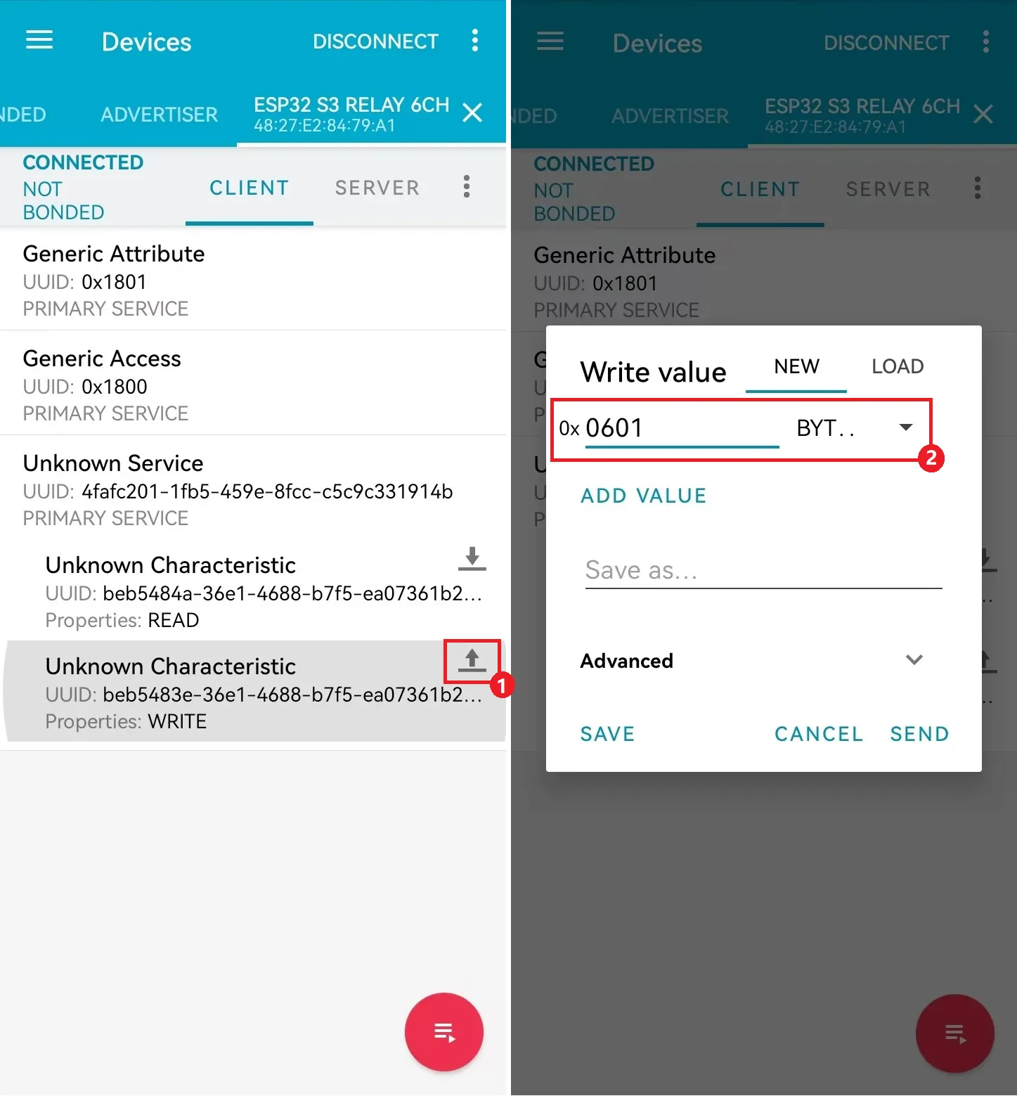
-
Sending
0x06 0x01toggles the state of relay CH1.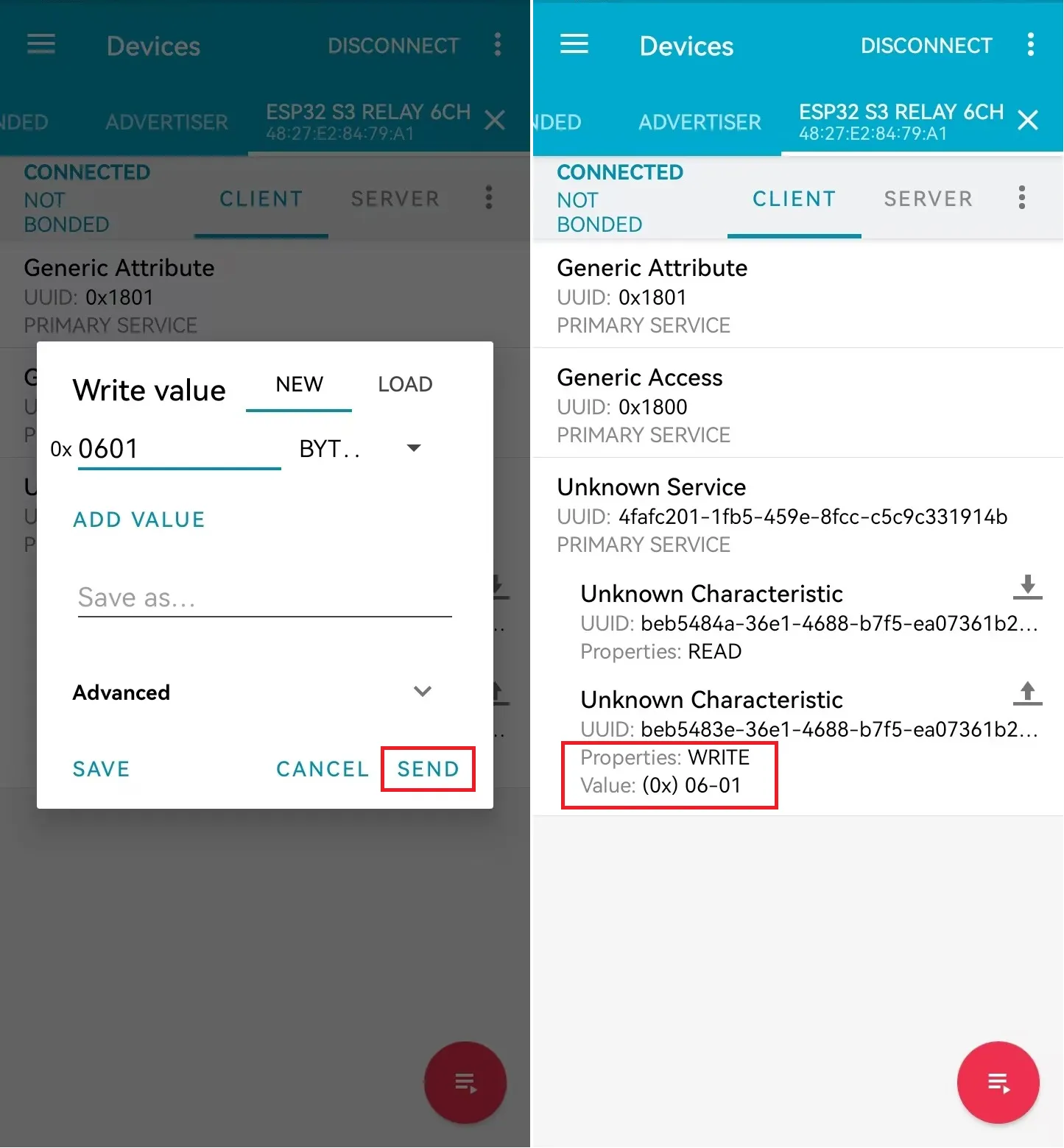
-
Sending
0x06 0x0Aturns off all relays.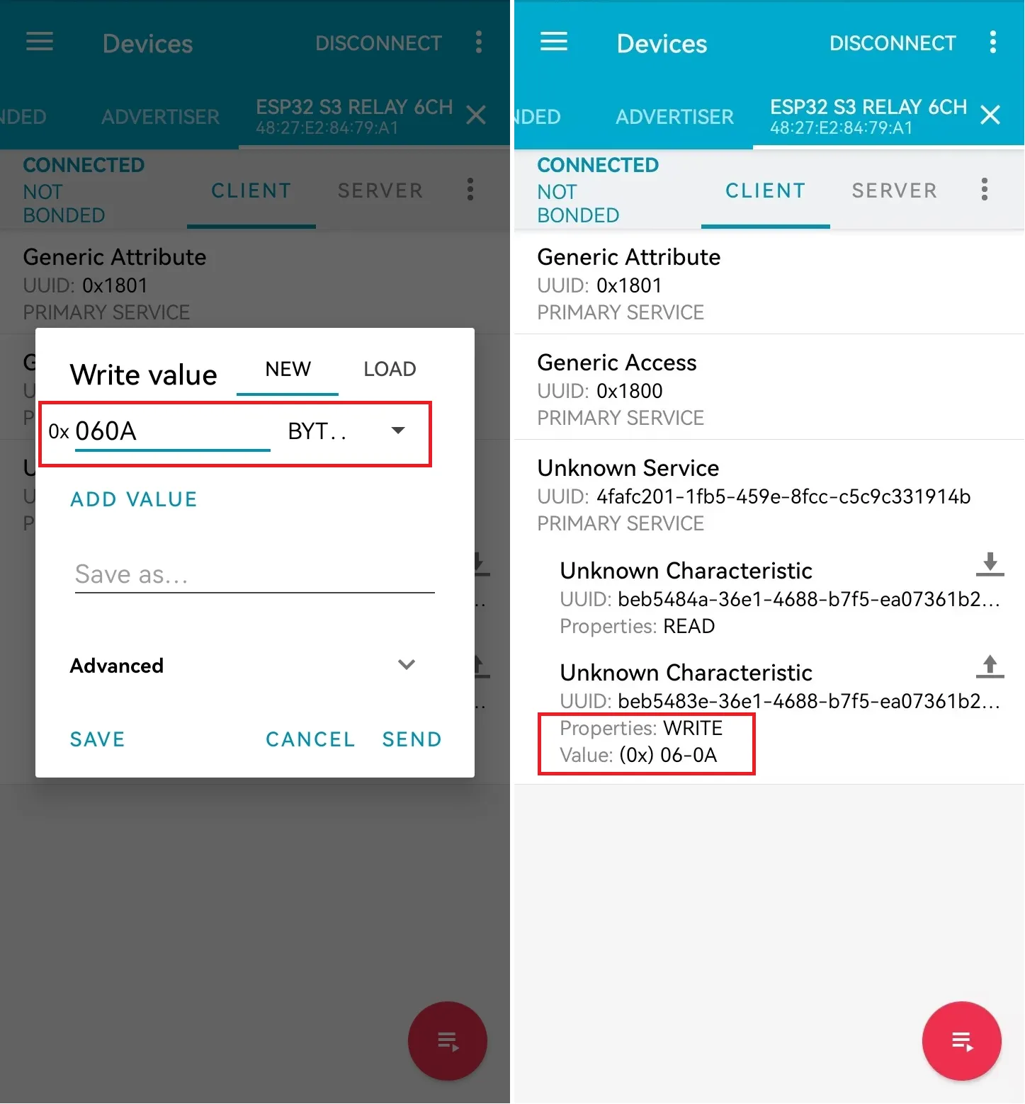
Expanding Timer Switch Function via Pico Interface
-
Use Pico-RTC-DS3231 to expand the timer switch function.
-
Before connecting the RTC module, ensure the RTC module time is accurate or connect the device to Wi-Fi to update the RTC module time; only then can the RTC timer function work properly.
-
Connect the Pico-RTC-DS3231 device to the ESP32-S3-Relay-6CH.
-
The 4 main example files are already compatible with this operation. You need to set
RTC_EnableinWS_imformation.hto 1 (default is 0; please ensure Pico-RTC-DS3231 is connected).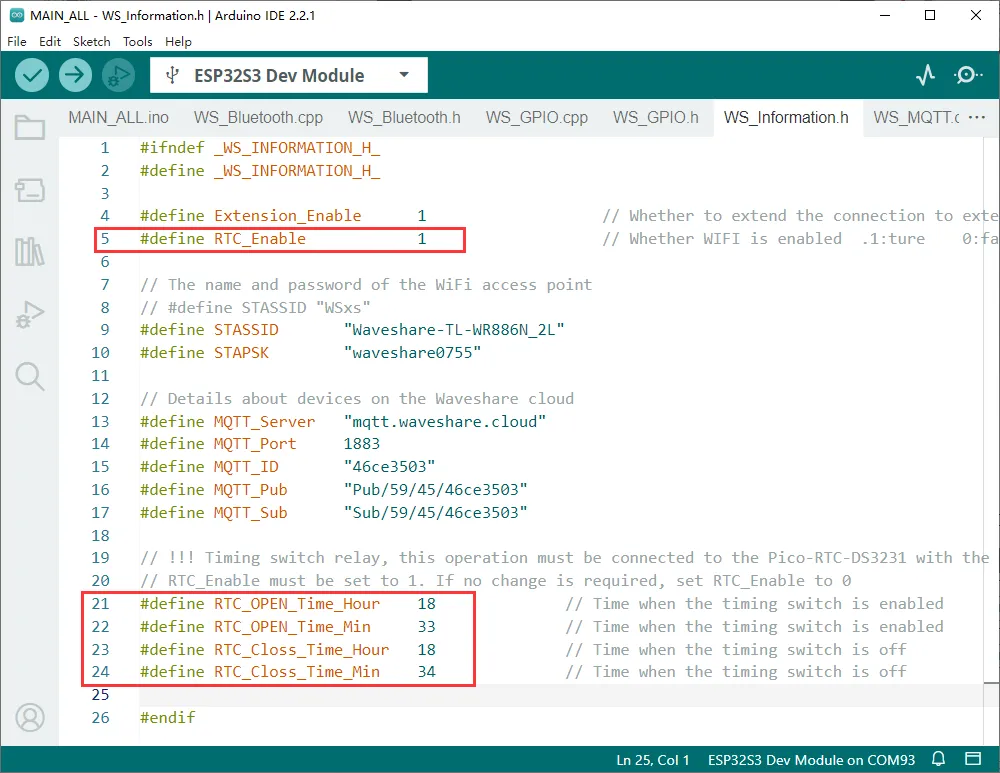
-
Set
RTC_OPEN_Time_Hour,RTC_OPEN_Time_Min,RTC_Closs_Time_Hour, andRTC_Closs_Time_MininWS_imformation.hto the operating times.Parameter Parameter Description RTC_OPEN_Time_Hour Time to turn on all relays — hour RTC_OPEN_Time_Min Time to turn on all relays — minute RTC_Closs_Time_Hour Time to turn off all relays — hour RTC_Closs_Time_Min Time to turn off all relays — minute -
For example, set to turn on at 8:06 and turn off at 16:30 every day.

Expanding CAN Interface via Pico Interface
- Use Pico-CAN-B to expand the CAN communication interface.
Preliminary Operations
-
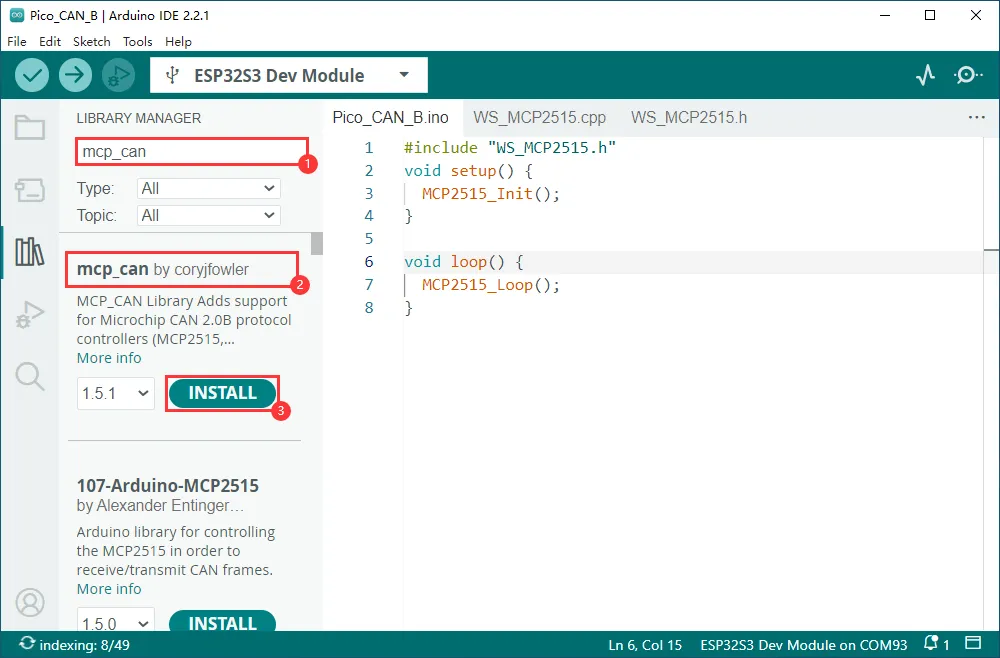
Install the mcp_can library.
Usage Instructions
-
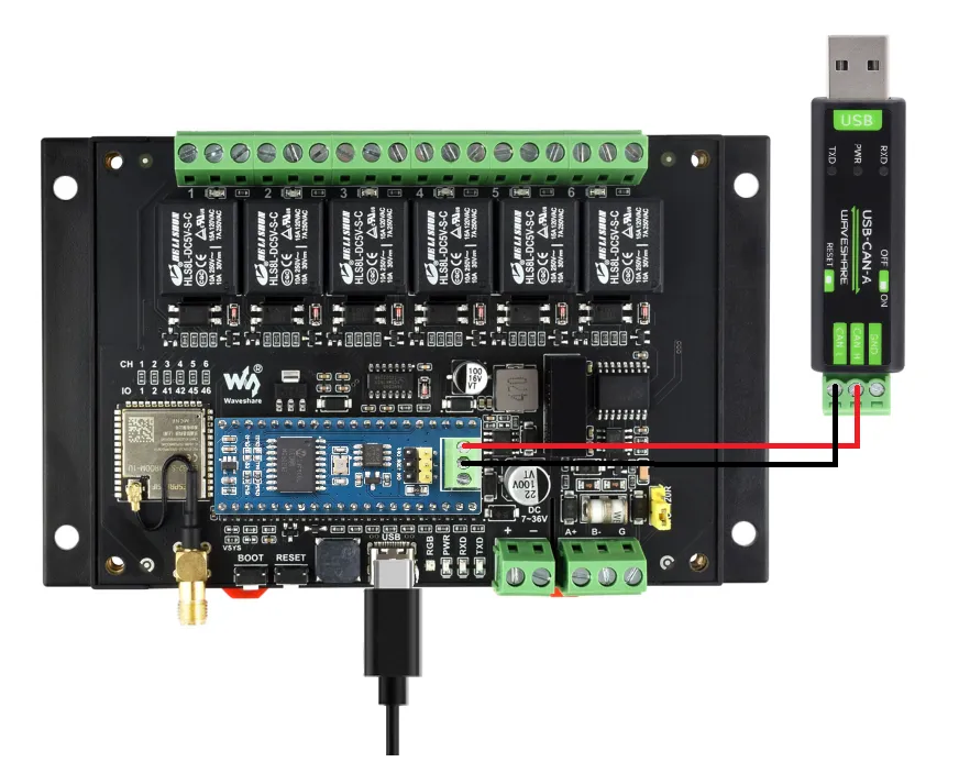
Connect the Pico-CAN-B device to the ESP32-S3-Relay-6CH.
-
Connect Pico-CAN-B to USB-CAN-A, then power on.
-
Download the provided Pico-CAN-B example.
-
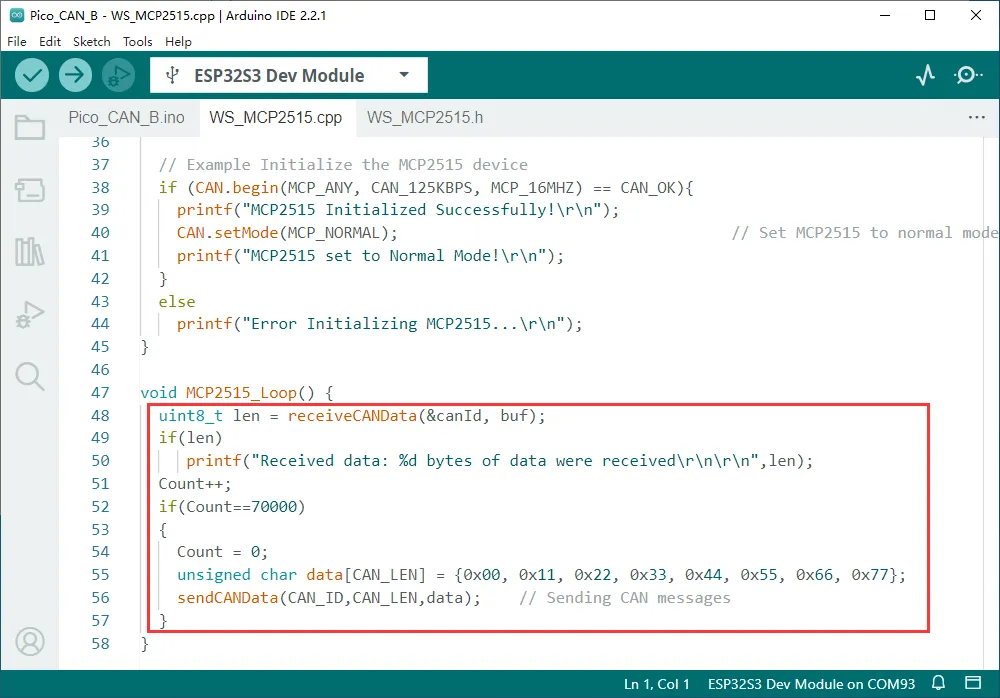
Modify the example according to your required operation.
-
In the main program, include
WS_MCP2515.candWS_MCP2515.h. -
After including them, you can use the functions
receiveCANData(uint32_t* canId, uint8_t* data)andsendCANData(uint32_t canId, uint8_t len, uint8_t* data)in the main program to receive and send CAN data.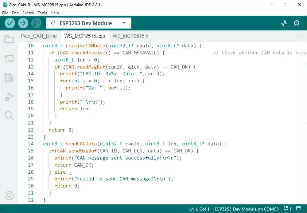
-
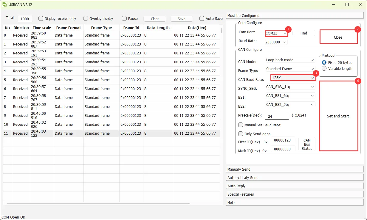
Data reception: Use USB-CAN-A_TOOL for debugging.
-
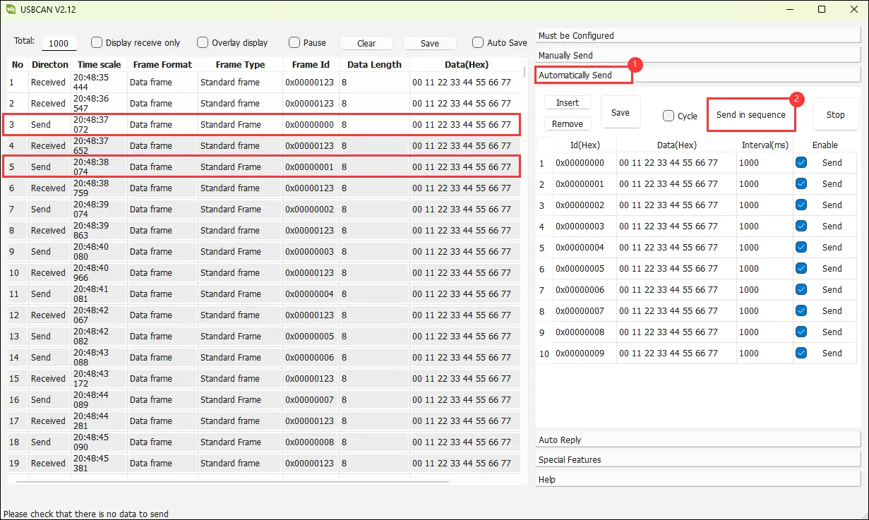
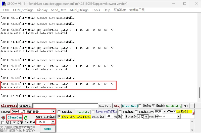
Data transmission: Use a serial debug assistant to view the printed data (you can also use the Arduino serial monitor).
Expanding Environmental Monitoring Function via Pico Interface
- Use Pico-Environment-Sensor to expand environmental detection functionality.
Preliminary Operations
-
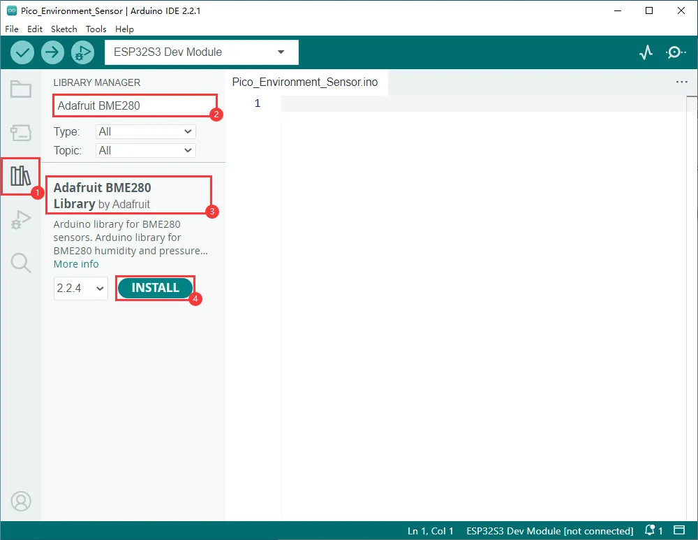
Install the Adafruit BME280 library.
-
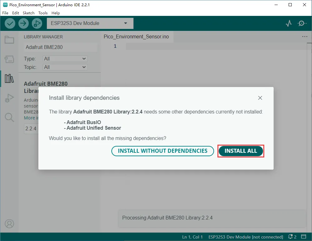
Select INSTALL ALL.
-
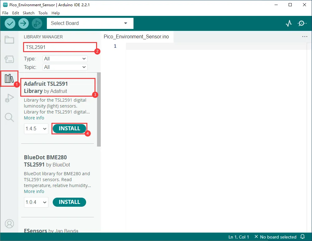
Install the Adafruit TSL2591 library.
-
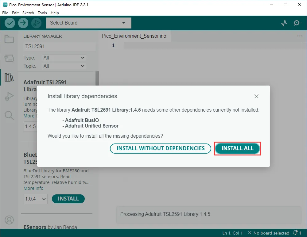
Select INSTALL ALL.
-
Install the Adafruit LTR390 library.
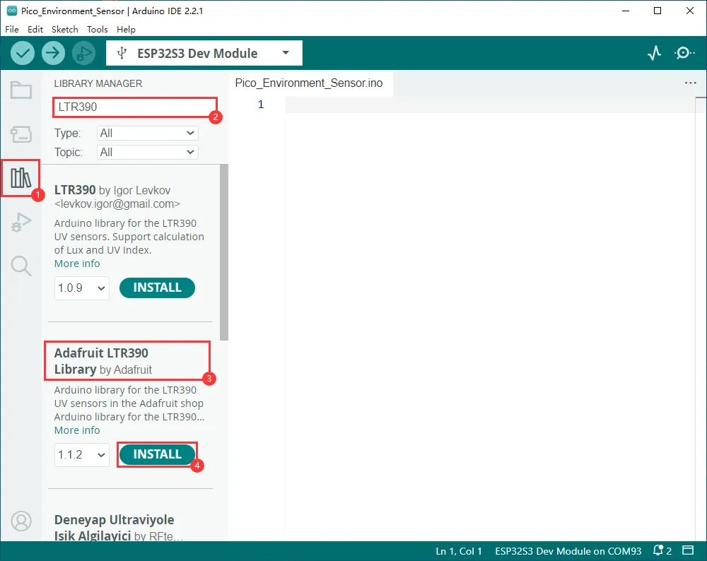
-
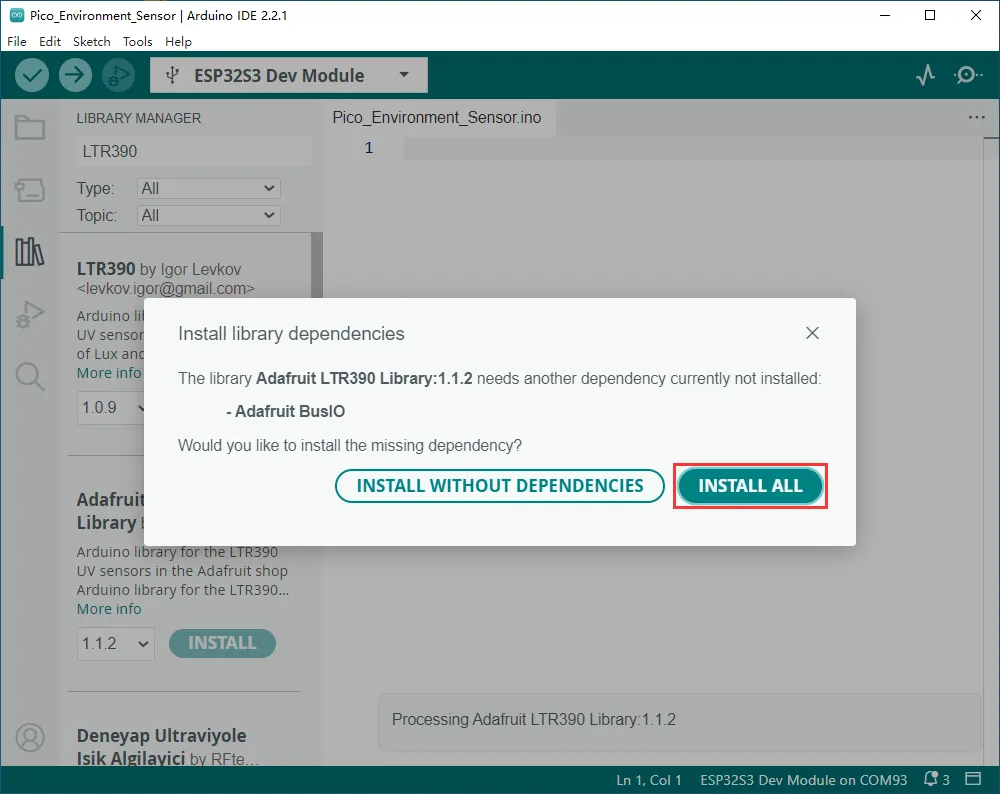
Select INSTALL ALL.
-
Install the Adafruit SGP40 library.
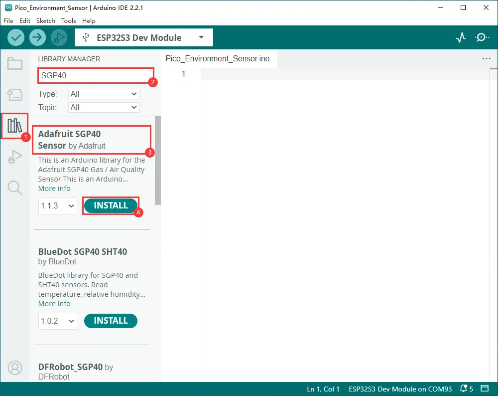
-
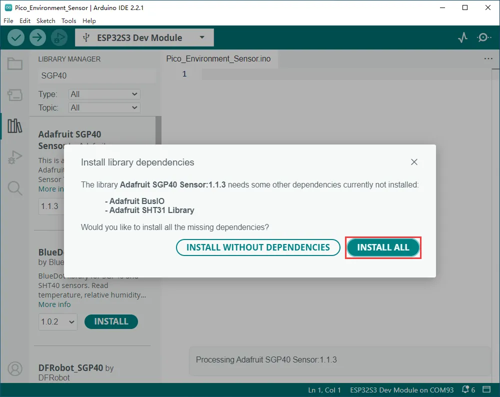
Select INSTALL ALL.
Usage Tutorial
-
Connect the Pico-Environment-Sensor device to the ESP32-S3-Relay-6CH.
-
Download the provided Pico-Environment-Sensor example.
-
In the main program, include
Environment_Sensor.candEnvironment_Sensor.h. -
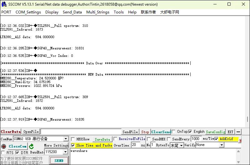
Modify the program as needed. The default program running results can also be viewed in the Arduino serial monitor.
Expanding RS232/RS485 Interface via Pico Interface
- Please note that when using Pico-2CH-RS485 to expand the RS485 interface, only channel 1 is supported; channel 0 cannot be used.
- Use Pico-2CH-RS232 to expand the RS232 communication interface.
Usage Tutorial
-
Connect the Pico-2CH-RS232 or Pico-2CH-RS485 device to the ESP32-S3-Relay-6CH.
-
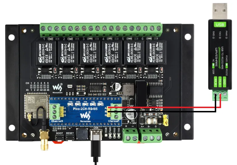
Connect the Pico-2CH-RS485 device to the USB TO RS232/485 converter. The method for Pico-2CH-RS232 is the same.
-
Download the provided Pico-2CH-RS232 example (the example applies to both devices above).
-
In the main program, include
WS_UART.h. -
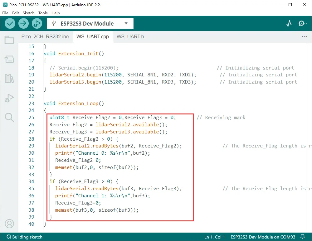
Modify the program according to your required operation.
-
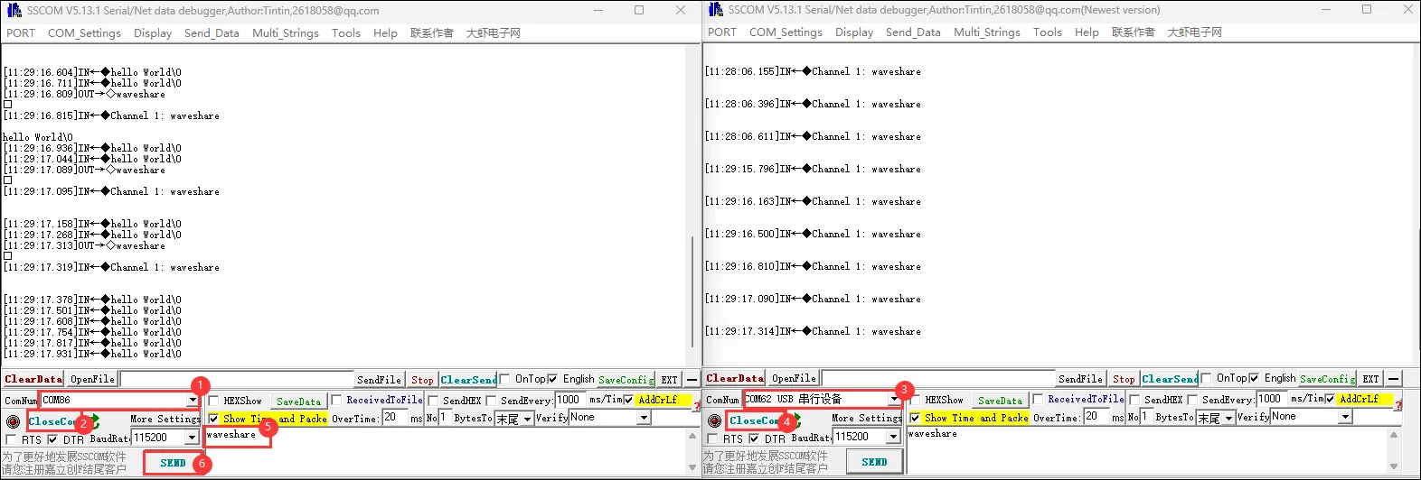
Currently, it prints received characters in real time.
-
Call the initialization function
Extension_Init()insetup. -
After calling it, you can use the functions
SetData2(uint8_t* data, size_t length)andSetData3(uint8_t* data, size_t length)in the main loop to send data.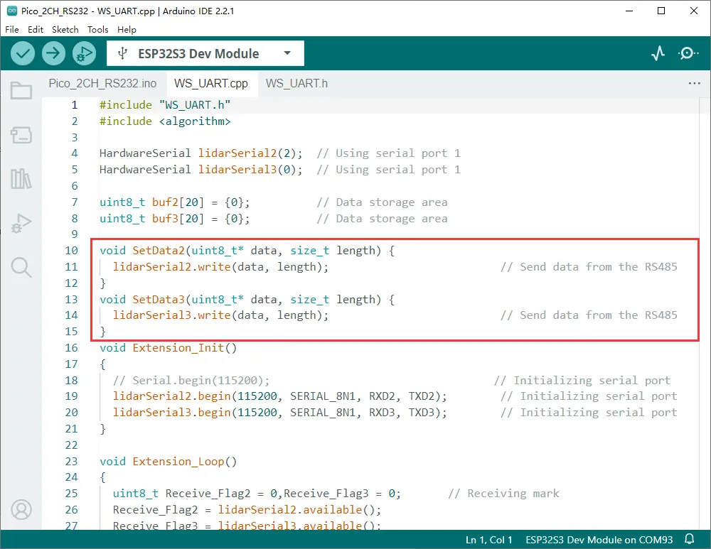
-
Default program communication process: USB to RS485 converter communicates with ESP32-S3-Relay-6CH via Pico-2CH-RS485.