ESP32-S3-Relay-6CH Working with MicroPython
This chapter includes the following sections. Please read as needed:
MicroPython Getting Started
New to ESP32 MicroPython development and looking for a quick start? We have prepared a comprehensive ESP32 MicroPython Getting Started Tutorial for you.
- Section 1: Setup Development Environment
- Section 2: Basics
- Section 3: GPIO Digital Output/Input
- Section 4: ADC Analog Input
- Section 5: PWM Output
- Section 6: UART Communication
- Section 7: I2C Communication
- Section 8: SPI Communication
- Section 9: Wi-Fi Basic
- Section 10: Web Server
- Section 11: Bluetooth
- Section 12: Comprehensive Project
Note: This tutorial uses the ESP32-S3-Zero as a teaching example, and all hardware code is based on its pinout. Before proceeding, we recommend checking the pinout diagram of your specific development board to ensure the pin configuration is correct.
Setting Up the Development Environment
1. Configure Thonny and Flash MicroPython Firmware
- Please refer to the Setting up the Development Environment to flash the MicroPython firmware.
2. Additional Tips
- The development board currently uses custom firmware for development. The firmware is available in the ESP32-S3-Relay-6CH Example. Note that the download address is the 0x00 position.
- Firmware path:
../ESP32-S3-Relay-6CH-Demo/MicroPython/Firmware - The bin file under Firmware, which is at the same level as the Arduino and MicroPython folders, is for testing onboard functions and do not need to be flashed here.
Refer to MicroPython Firmware Compilation for more learning resources.
Example

ESP32-S3-Relay-6CH Example Programs
| Example | Basic Description |
|---|---|
| main.py | Main function |
| ws_bluetooth.py | Bluetooth initialization and command parsing |
| ws_gpio.py | RGB, buzzer, and relay initialization |
| ws_information.py | Global system parameter settings |
| ws_relay.py | Implements relay control |
| ws_serial.py | 8-channel relay expansion |
Uploading the Example
-
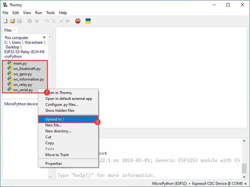
To upload local files to the development board, select the file, right-click, and find "upload to/" to upload.
-
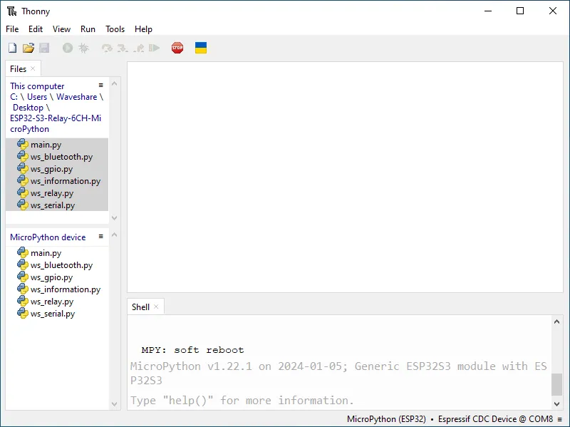
The following is the interface after all files are uploaded. The uploaded files must match those in the image; otherwise, it may fail to run.
Running the Example
After running the example, you can control the onboard relays through RS485 or Bluetooth.
RS485 Control
Connect an external RS485 device to the ESP32-S3-Relay-6CH to control its relays. Send control commands to toggle or change the state of each relay. The default baud rate is 9600.
Control Command Table
| Operation Command | Command Function |
|---|---|
| 06 05 00 01 55 00 A2 ED | Toggle CH1 relay state |
| 06 05 00 02 55 00 52 ED | Toggle CH2 relay state |
| 06 05 00 03 55 00 03 2D | Toggle CH3 relay state |
| 06 05 00 04 55 00 B2 EC | Toggle CH4 relay state |
| 06 05 00 05 55 00 E3 2C | Toggle CH5 relay state |
| 06 05 00 06 55 00 13 2C | Toggle CH6 relay state |
| 06 05 00 FF FF 00 BD BD | Turn on all relays |
| 06 05 00 FF 00 00 FC 4D | Turn off all relays |
Hardware Connection
This example uses a USB TO RS232/485 Converter for the connection demonstration. Match the pins as follows:
| ESP32-S3-Relay-6CH | USB-TO-RS232-485 |
|---|---|
| RS485 - A+ | Tx B - A+ |
| RS485 - B- | Rx B - B- |
Software Operation
-
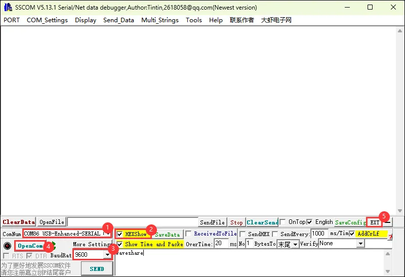
Open SSCOM, select the COM port corresponding to Port B, and set the baud rate to
9600. -
Open the serial port, prepare relay commands in the multi-send list, and enable hexadecimal (HEX) sending.
-
Click the send button beside the required command to control the relays.
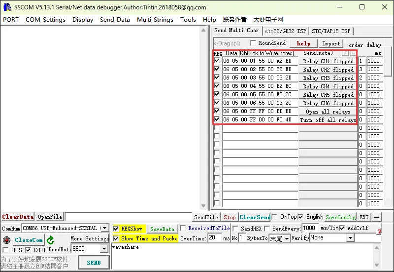
Bluetooth Control
Use the mobile nRF Connect app to demonstrate Bluetooth control. Other Bluetooth debugging apps can also be used.
Some Bluetooth debugging apps send data as ASCII strings by default, while others send hexadecimal data. Choose the command format supported by the app.
Control Command Table
| ASCII | Hex | Command Function |
|---|---|---|
| 1 | 0x31 | Toggle CH1 relay state |
| 2 | 0x32 | Toggle CH2 relay state |
| 3 | 0x33 | Toggle CH3 relay state |
| 4 | 0x34 | Toggle CH4 relay state |
| 5 | 0x35 | Toggle CH5 relay state |
| 6 | 0x36 | Toggle CH6 relay state |
| 7 | 0x37 | Turn on all relays |
| 8 | 0x38 | Turn off all relays |
Operation Steps
The example uses the mobile nRF Connect app for demonstration. Other Bluetooth debugging apps can also be used.
-
Open nRF Connect, scan for Bluetooth devices, and connect to
ESP32 S3 Relay 6CH.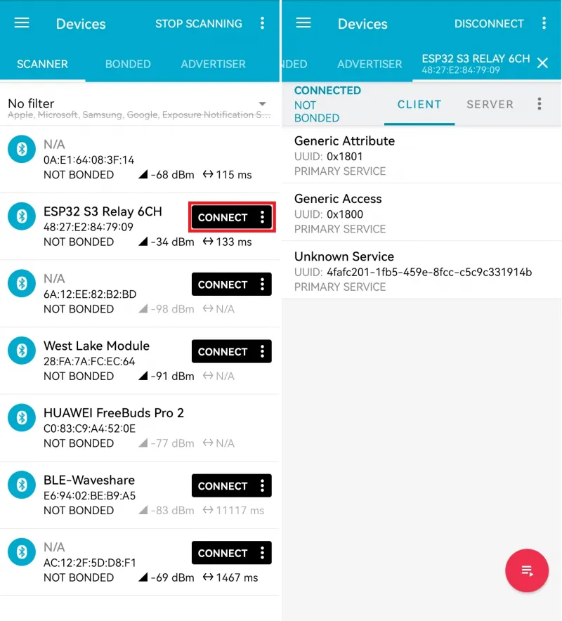
-
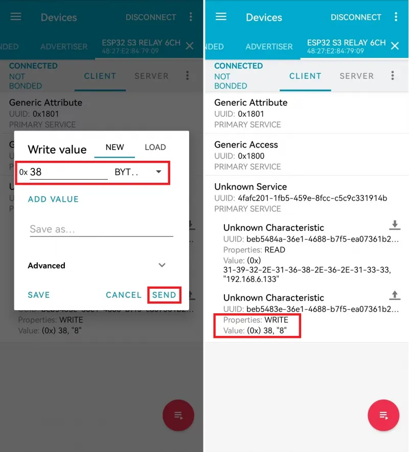
Read the device IP (optional): After connecting, expand Unknown Service and tap the read button (down arrow). If Wi-Fi connects successfully, the device returns its IP address. If Wi-Fi fails to connect for a long time, the RGB LED remains red and the read returns no data.
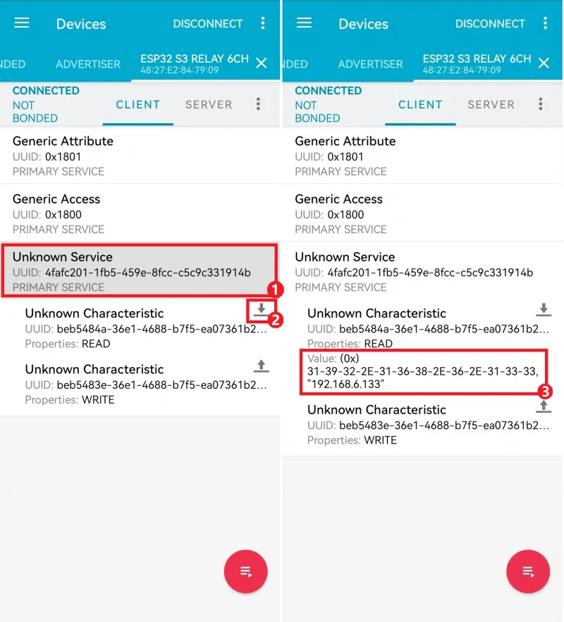
-
Send a control command: The relay commands are characters
1to8(hexadecimal0x31to0x38). Tap the send button (up arrow), select the hexadecimal BYTE data type, and enter31.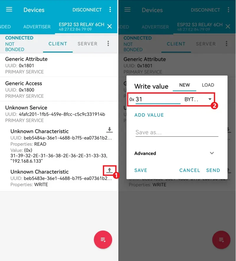
-
Sending
0x31toggles the state of relay CH1.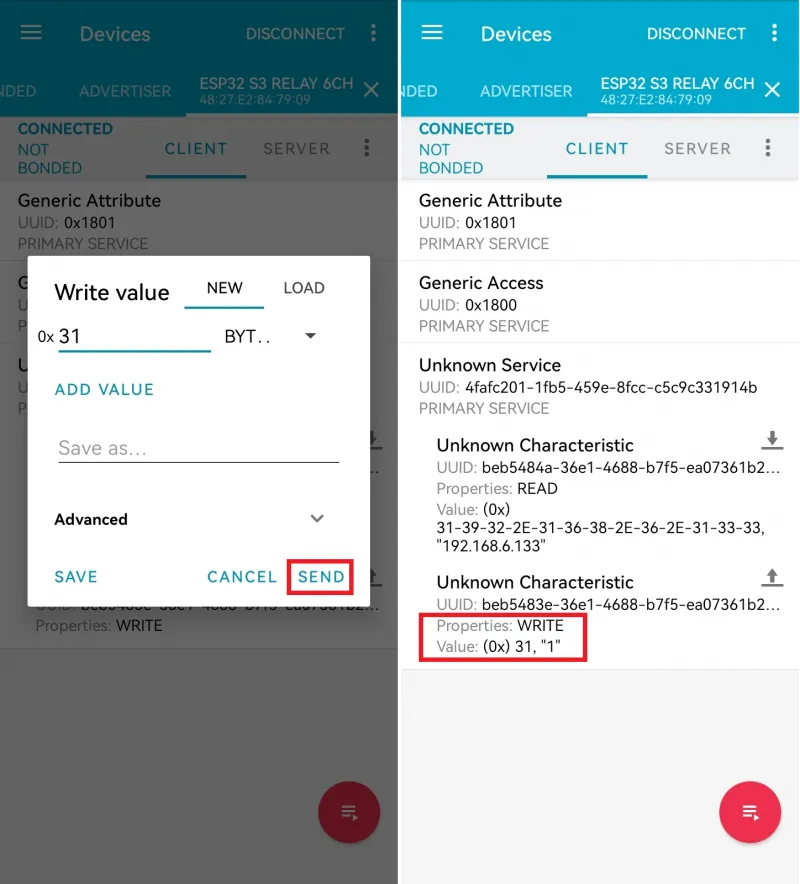
-
To turn off all relays, send
0x38.