Working with Arduino
This chapter includes the following sections. Please read as needed:
Arduino Getting Started
New to Arduino ESP32 development and looking for a quick start? We have prepared a comprehensive Getting Started Tutorial for you.
- Section 0: Getting to Know ESP32
- Section 1: Installing and Configuring Arduino IDE
- Section 2: Arduino Basics
- Section 3: Digital Output/Input
- Section 4: Analog Input
- Section 5: Pulse Width Modulation (PWM)
- Section 6: Serial Communication (UART)
- Section 7: I2C Communication
- Section 8: SPI Communication
- Section 9: Wi-Fi Basics
- Section 10: Web Server
- Section 11: Bluetooth
- Section 12: LVGL GUI Development
- Section 13: Comprehensive Project
Note: This tutorial uses the ESP32-S3-Zero as a reference example, and all hardware code is based on its pinout. Before you start, we recommend checking the pinout of your development board to ensure the pin configuration is correct.
Setting Up the Development Environment
1. Installing and Configuring the Arduino IDE
Please refer to the tutorial Install and Configure Arduino IDE to download and install the Arduino IDE and add ESP32 support.
2. Installing Libraries
- When installing Arduino libraries, there are typically two methods: online installation and offline installation. If the library installation requires offline installation, you must use the provided library files.
- For most libraries, you can search and install them via the Arduino IDE's Library Manager. However, some open-source or custom libraries are not synchronized to the Arduino Library Manager and therefore cannot be found through online search. In such cases, these libraries must be installed manually offline.
- You can download the example program package for the ESP32-S3-Touch-AMOLED-1.43 board from here. The
Arduino\librariesdirectory within the package already contains all the library files required for this tutorial.
| Library or File Name | Description | Version | Installation Method |
|---|---|---|---|
| LVGL | UI Graphics Library | v8.4.0 | Offline Installation |
There are strong dependencies between versions of LVGL and its driver libraries. For example, a driver written for LVGL v8 may not be compatible with LVGL v9. To ensure that the examples can be reproduced reliably, it is recommended to use the specific versions listed in the table above. Mixing different versions of libraries may lead to compilation failures or runtime errors.
Installation Steps:
-
Navigate to the downloaded example package.
-
Copy all folders (Arduino_DriveBus, GFX_Library_for_Arduino, etc.) in the
Arduino\librariesdirectory to the Arduino library folder.infoThe path to the Arduino libraries folder is typically:
c:/Users/<username>/Documents/Arduino/libraries.You can also locate it in the Arduino IDE by going to File > Preferences and checking the "Sketchbook location". The libraries folder is the
librariessubfolder within this path. -
For other installation methods, please refer to: Arduino Library Management Tutorial.
Example
The Arduino examples are located in the Arduino/examples directory of the example package.
| Example | Basic Description | Dependency Library |
|---|---|---|
| 01_ADC_Test | Read the current system voltage | - |
| 02_I2C_PCF85063 | Print the real-time clock from the RTC chip | - |
| 03_I2C_QMI8658 | Print raw data from the IMU | - |
| 04_SD_Card | Load and display TF card information | - |
| 05_WIFI_AP | Set to AP mode to get IP addresses of connected devices | - |
| 06_WIFI_STA | Set to STA mode to connect to Wi-Fi and obtain an IP address | - |
| 07_LVGL_Test | LVGL example | LVGL |
Arduino Project Settings
-
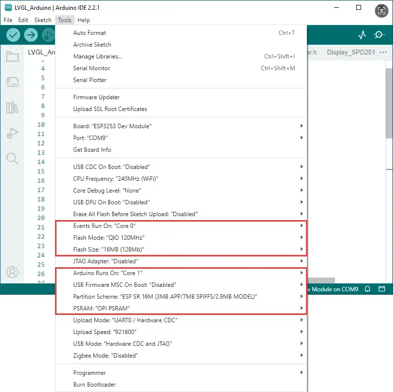
If the example being flashed contains a speech recognition model, select "ESP SR 16M (3MB APP/7MB SPIFFS/2.9MB MODEL)" for the Partition Scheme.
-
If the example being flashed does not contain a speech recognition model, select "16M Flash (3MB APP/9.9MB FATFS)" or another appropriate scheme.
01_ADC_Test
Example Description
- The analog voltage connected via GPIO is converted to a digital value by the ADC, then the actual system voltage is calculated and printed to the terminal.
Hardware Connection
-
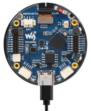
Connect the board to the computer using a USB cable.
Code Analysis
adc_bsp_init: Initializes ADC1, including creating an ADC single-shot unit and configuring channel 3 of ADC1.adc_get_value: Reads the value from ADC1 channel 3, calculates the corresponding voltage based on the reference voltage and resolution, and stores it in the location pointed to by the passed pointer. If reading fails, it stores 0.adc_example: After initializing ADC1, creates an ADC task that reads the ADC value every second and calculates the system voltage from the raw ADC reading.
Expected Behavior
-
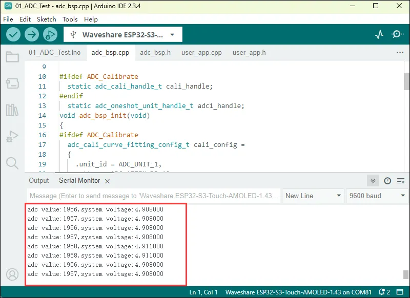
After the program is compiled and downloaded, you can view the printed ADC values and voltage output by opening the Serial Monitor, as shown in the following image:
-
The ADC raw value is around 1900, and the system voltage is approximately 4.9 V. For a more detailed analysis, refer to the schematic.
02_I2C_PCF85063
Example Description
- Using the I2C protocol, the PCF85063 chip is initialized, time is set, and time is read at intervals, then printed to the terminal.
Hardware Connection
-
Connect the board to the computer using a USB cable.
Code Analysis
void PCF85063_example: Creates an RTC task to implement RTC functionality, reading the clock from the RTC chip every 10 seconds and outputting it to the terminal.
Expected Behavior
-
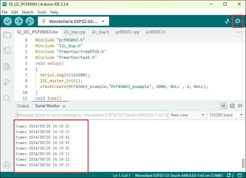
Open the serial port monitoring, you can see the RTC time of the printout, as shown in the figure below:
-
Data is output every 10 seconds. For modifications or references, you can directly edit the pcf85063 source file.
03_I2C_QMI8658
Example Description
- Using the I2C protocol, the QMI8658 chip is initialized, and then attitude information is read every second and printed to the terminal.
Hardware Connection
-
Connect the board to the computer using a USB cable.
Code Analysis
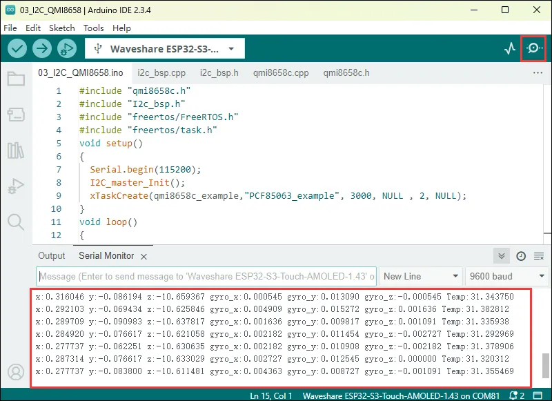
qmi8658c_example: This function initializes the QMI8658 device. In an infinite loop, it reads and prints accelerometer, gyroscope, and temperature data every second. As the board rotates, the gyroscope data increases with faster rotation, and the accelerometer calculates the corresponding acceleration based on the current position.
Expected Behavior
-
Open the Serial Monitor to see the printed raw data from the IMU (Euler angles need to be converted by yourself), as shown in the figure below:
-
Data is output every second. For modifications or references, you can directly edit the qmi source file.
04_SD_Card
Example Description
- Using a macro definition to select either SPI or SDMMC to drive the TF card. After successfully mounting the TF card, the TF card information is printed to the terminal.
Hardware Connection
-
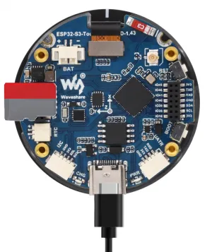
Insert a TF card (must be smaller than 64 GB) into the board, then connect the board to your computer via USB cable.
Code Analysis
- The communication protocol for the TF card can be selected via a macro definition. In the
sd_card_bsp.cppsource file, find the macroSD_Read_Mode. It defaults to SDMMC, but can be changed to SDSPI.
#define SD_Read_Mode USER_SPI
Expected Behavior
-
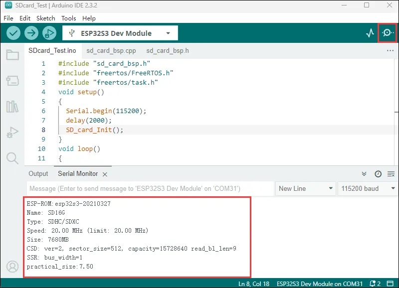
Click to open the Serial Monitor device. You can see the output TF card information; practical_size indicates the actual capacity of the TF card, as shown below:
Want to learn more about using the TF card with the Arduino ESP32 library? Please refer to Arduino ESP32 TF Library Usage
05_WIFI_AP
Example Description
- Configure the board as an AP to wait for STA connections.
Hardware Connection
-
Connect the board to the computer using a USB cable.
Code Analysis
- This code initializes serial communication on the ESP32 and creates a Wi-Fi access point named "bsp_esp_demo" with password "waveshare". After setup, no other operations are performed in the loop.
const char* ssid     = "bsp_esp_demo";
const char* password = "waveshare";

WiFi.softAP(ssid, password);
Expected Behavior
-
Use a phone or other device to connect to the Wi-Fi network named "bsp_esp_demo" with password "waveshare".

06_WIFI_STA
Example Description
- Configure the board as a STA to connect to an available AP. Upon successful connection, the acquired IP information is printed to the terminal.
Hardware Connection
-
Connect the board to the computer using a USB cable.
Code Modification
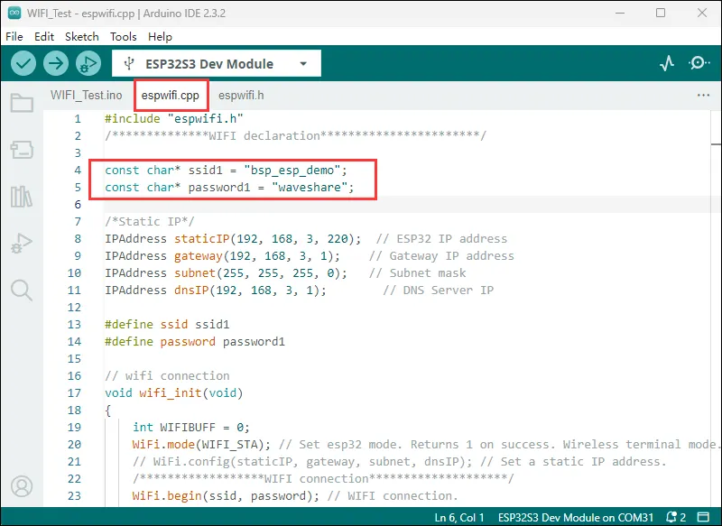
This example configures the chip in STA mode to connect to Wi-Fi and obtain an IP address. Before compiling and flashing the firmware, you need to modify the code to use a Wi-Fi router name and password available in your environment.
Code Analysis
wifi_init(void): This function initializes the Wi-Fi connection of the ESP32. It sets the ESP32 to Wi-Fi station mode and attempts to connect to the specified Wi-Fi network (via ssid and password). If connection is successful, it prints the local IP address. If connection fails within a certain period (20 * 500 ms), it prints a connection failure message. At the same time, the function can also set the auto-connection and auto-reconnect functions
Expected Behavior
-
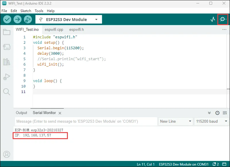
When the chip successfully connects to Wi-Fi in STA mode, open the serial monitor to see the acquired IP address.
07_LVGL-Test
Example Description
- By porting LVGL, a multi-functional GUI interface is displayed on the screen.
Hardware Connection
-
Connect the board to the computer using a USB cable.
Code Analysis
For LVGL, lvgl_conf.h is its configuration file. Some common settings are described below. LVGL examples and file systems can also be configured in the conf file.
/*Color depth: 1 (1 byte per pixel), 8 (RGB332), 16 (RGB565), 32 (ARGB8888)*/
#define LV_COLOR_DEPTH 16//Color depth, a macro definition that must be concerned with porting LVGL

#define LV_MEM_CUSTOM 0
#if LV_MEM_CUSTOM == 0
    /*Size of the memory available for `lv_mem_alloc()` in bytes (>= 2kB)*/
    #define LV_MEM_SIZE (48U * 1024U)          /*[bytes]*/

    /*Set an address for the memory pool instead of allocating it as a normal array. Can be in external SRAM too.*/
    #define LV_MEM_ADR 0     /*0: unused*/
    /*Instead of an address give a memory allocator that will be called to get a memory pool for LVGL. E.g. my_malloc*/
    #if LV_MEM_ADR == 0
        #undef LV_MEM_POOL_INCLUDE
        #undef LV_MEM_POOL_ALLOC
    #endif

#else       /*LV_MEM_CUSTOM*/
    #define LV_MEM_CUSTOM_INCLUDE <stdlib.h>   /*Header for the dynamic memory function*/
    #define LV_MEM_CUSTOM_ALLOC   malloc
    #define LV_MEM_CUSTOM_FREE    free
    #define LV_MEM_CUSTOM_REALLOC realloc
#endif     /*LV_MEM_CUSTOM*/
//The above section is mainly for LVGL memory allocation,
//which defaults to lv_mem_alloc() versus lv_mem_free().
Code Modification
The display chip itself does not support hardware rotation. If rotation is needed, it can be done via software. In the lcd_bsp.c file, find the macro #define EXAMPLE_Rotate_90 and uncomment it. Note that software rotation requires an additional framebuffer copy, resulting in a lower frame rate compared to hardware rotation.
#define EXAMPLE_Rotate_90
Expected Behavior
-
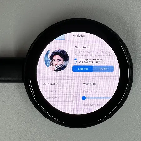
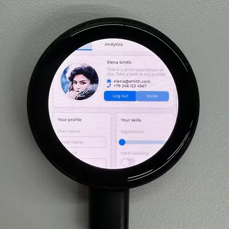
The LVGL example has high RAM and ROM requirements, so the environment must be configured as required. After the example is flashed, the running result of the device is as follows:
For more LVGL learning and usage, refer to the LVGL Official Documentation.