ESP-IDF
This chapter includes the following sections. Please read as needed:
ESP-IDF Getting Started
New to ESP32 ESP-IDF development and looking to get started quickly? We have prepared a general Getting Started Tutorial for you.
- Section 1: Environment Setup
- Section 2: Running Examples
- Section 3: Creating a Project
- Section 4: Using Components
- Section 5: Debugging
- Section 6: FreeRTOS
- Section 7: Peripherals
- Section 8: Wi-Fi Programming
- Section 9: BLE Programming
Please Note: This tutorial uses the ESP32-S3-Zero as a teaching example, and all hardware code is based on its pinout. Before you start, it is recommended that you check the pinout of your development board to ensure the pin configuration is correct.
Setting Up the ESP-IDF Development Environment
The ESP32-S3-Touch-AMOLED-1.43 development board requires ESP-IDF V5.3.1 or later.
The following guide uses Windows as an example, demonstrating development using VS Code + the ESP-IDF extension. macOS and Linux users should refer to the official documentation.
The screenshots in this section use ESP-IDF V5.5.2 as an example. When installing, please select the ESP-IDF version that matches your board's example.
Install the ESP-IDF Development Environment
-
Download the installation manager from the ESP-IDF Installation Manager page. This is Espressif's latest cross-platform installer. The following steps demonstrate how to use its offline installation feature.
Click the Offline Installer tab on the page, then select Windows as the operating system and the ESP-IDF version you need (the version shown in the screenshot is for reference only — choose the version that fits your actual needs).
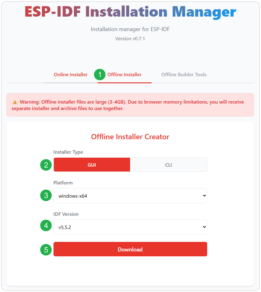
After confirming your selection, click the download button. The browser will automatically download two files: the ESP-IDF Offline Package (.zst) and the ESP-IDF Installer (.exe).
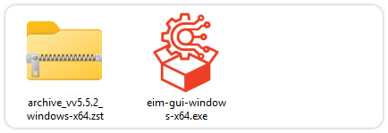
Please wait for both files to finish downloading.
-
Once the download is complete, double-click to run the ESP-IDF Installer (eim-gui-windows-x64.exe).
The installer will automatically detect if the offline package exists in the same directory. Click Install from archive.
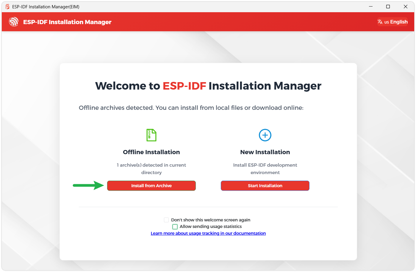
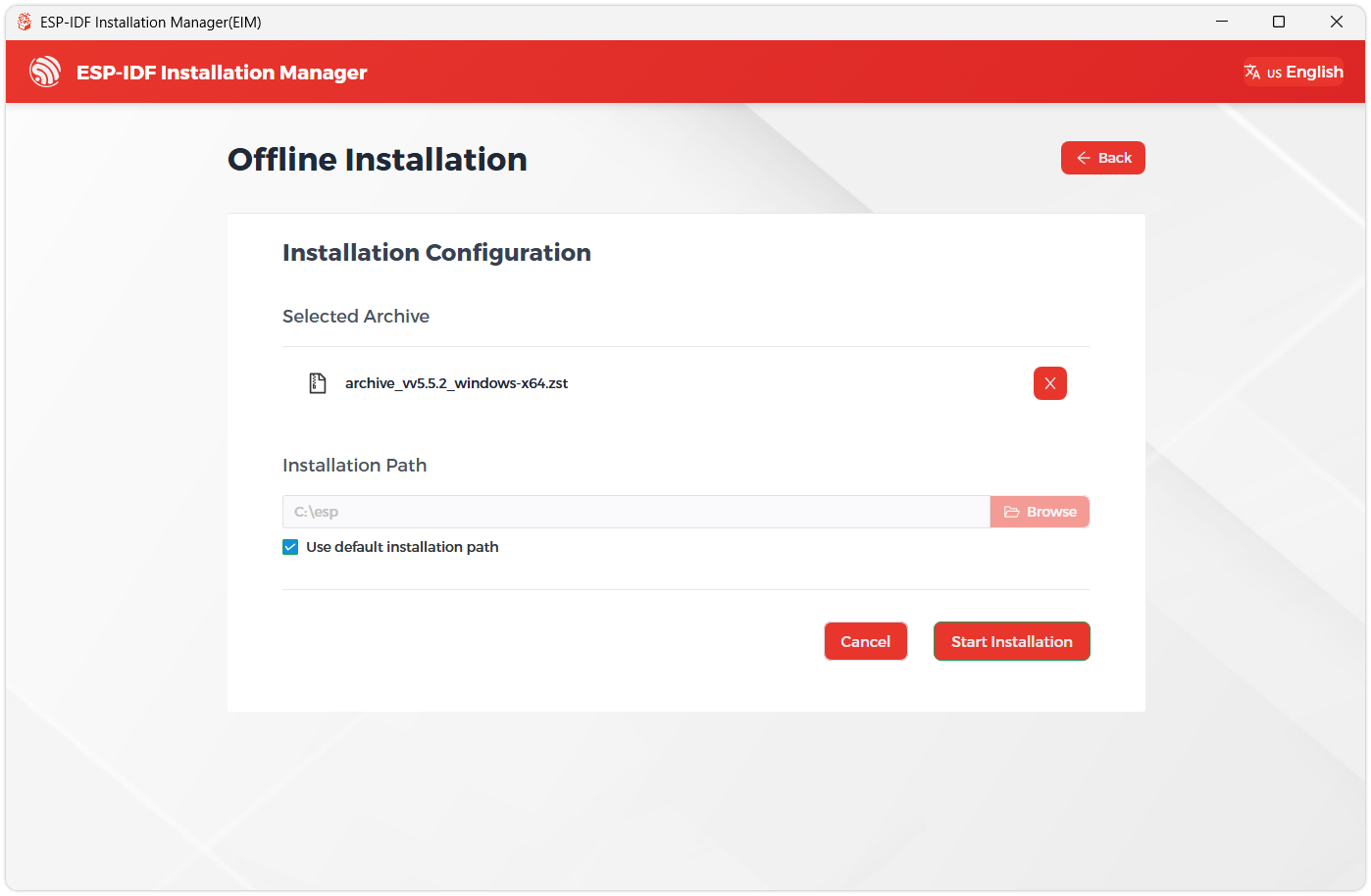
Next, select the installation path. We recommend using the default path. If you need to customize it, ensure the path does not contain Chinese characters or spaces. Click Start installation to proceed.
-
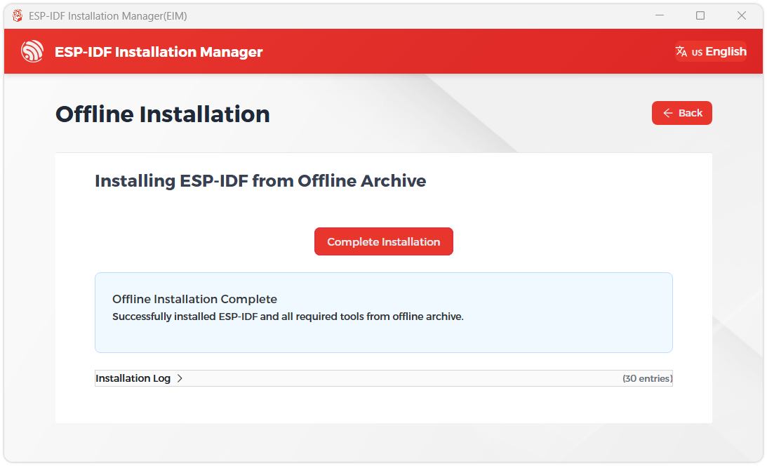
When you see the following screen, the ESP-IDF installation is successful.
-
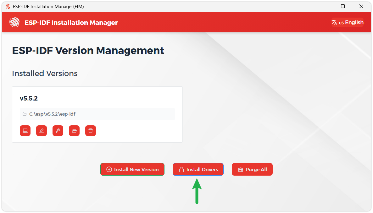
We recommend installing the drivers as well. Click Finish installation, then select Install driver.
Install Visual Studio Code and the ESP-IDF Extension
-
Download and install Visual Studio Code.
-
During installation, it is recommended to check Add "Open with Code" action to Windows Explorer file context menu to facilitate opening project folders quickly.
-
In VS Code, click the Extensions icon
 in the Activity Bar on the side (or use the shortcut Ctrl + Shift + X) to open the Extensions view.
 -
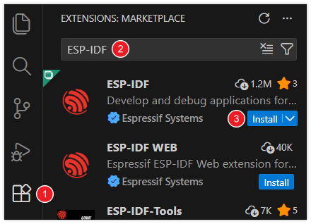
Enter ESP-IDF in the search box, locate the ESP-IDF extension, and click Install.
-
For ESP-IDF extension versions ≥ 2.0, the extension will automatically detect and recognize the ESP-IDF environment installed in the previous steps, requiring no manual configuration.
Example
The ESP-IDF example programs are located in the ESP-IDF directory of the example package.
| Example | Basic Description | Dependency Library |
|---|---|---|
| 01_ADC_Test | Read the current system voltage | - |
| 02_I2C_PCF85063 | Print the real-time clock from the RTC chip | - |
| 03_I2C_QMI8658 | Print raw data from the IMU | - |
| 04_SD_Card | Load and display TF card information | - |
| 05_WIFI_AP | Set to AP mode to get IP addresses of connected devices | - |
| 06_WIFI_STA | Set to STA mode to connect to Wi-Fi and obtain an IP address | - |
| 07_LVGL_Test | LVGL example | LVGL |
| 08_LVGL_SDIMG | Example combining LVGL, TF Card, and IMG | LVGL |
| 09_FactoryProgram | Comprehensive factory program | LVGL |
01_ADC_Test
Example Description
- The analog voltage connected via GPIO is converted to a digital value by the ADC, then the actual system voltage is calculated and printed to the terminal.
Hardware Connection
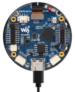
Connect the board to the computer using a USB cable
Code Analysis
adc_bsp_init(void): Initializes ADC1, including creating an ADC single-shot unit and configuring channel 3 of ADC1.adc_get_value(float *value,int *data): Reads the value from ADC1 channel 3, calculates the corresponding voltage based on the reference voltage and resolution, and stores it in the location pointed to by the passed pointer. If reading fails, it stores 0.adc_example(void* parameter): After initializing ADC1, creates an ADC task that reads the ADC value every second and calculates the system voltage from the raw ADC reading.
Expected Behavior
-
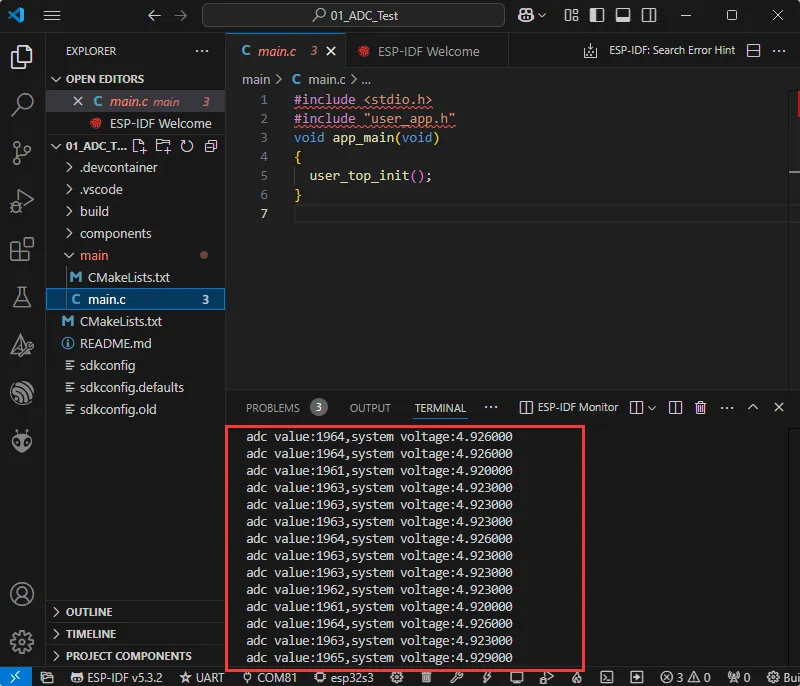
After the program is compiled and downloaded, you can view the printed ADC values and voltage output by opening the Serial Monitor, as shown in the following image:
-
The ADC raw value is around 1900, and the system voltage is approximately 4.9 V. For a more detailed analysis, refer to the schematic.
02_I2C_PCF85063
Example Description
- Using the I2C protocol, the PCF85063 chip is initialized, time is set, and time is read at intervals, then printed to the terminal.
Hardware Connection
Connect the board to the computer using a USB cable
Code Analysis
void PCF85063_example(void* parameter): Creates an RTC task to implement RTC functionality, reading the clock from the RTC chip every 10 seconds and outputting it to the terminal.
Expected Behavior
-
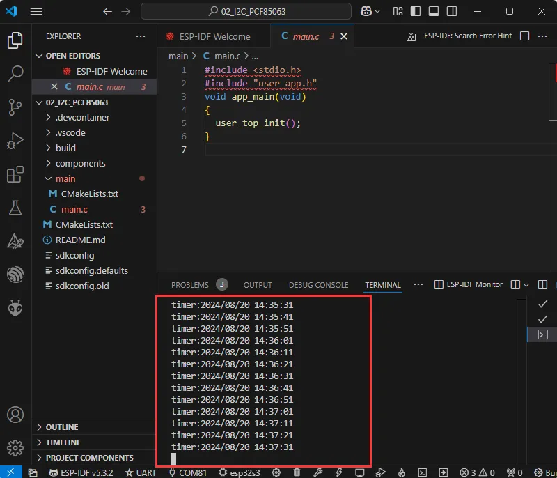
Open the serial port monitoring, you can see the RTC time of the printout, as shown in the figure below:
-
Data is output every 10 seconds. For modifications or references, you can directly edit the pcf85063 source file.
03_I2C_QMI8658
Example Description
- Using the I2C protocol, the QMI8658 chip is initialized, and then attitude information is read every second and printed to the terminal.
Hardware Connection
- Connect the board to the computer using a USB cable.
Code Analysis
qmi8658c_example(void* parameter): This function initializes the QMI8658 device. In an infinite loop, it reads and prints accelerometer, gyroscope, and temperature data every second. As the board rotates, the gyroscope data increases with faster rotation, and the accelerometer calculates the corresponding acceleration based on the current position.
Expected Behavior
-
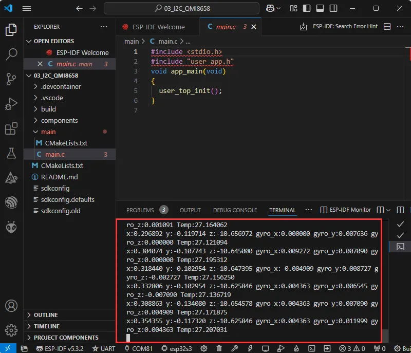
Open the Serial Monitor to see the printed raw data from the IMU (Euler angles need to be converted by yourself), as shown in the figure below:
-
Data is output every second. For modifications or references, you can directly edit the qmi source file.
04_SD_Card
Example Description
- Using a macro definition to select either SPI or SDMMC to drive the TF card. After successfully mounting the TF card, the TF card information is printed to the terminal.
Hardware Connection
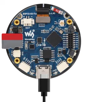
- Insert a TF card (must be smaller than 64 GB) into the board, then connect the board to your computer via USB cable.
Code Analysis
- The communication protocol for the TF card can be selected via a macro definition. In the
sd_card_bsp.cppsource file, find the macroSD_Read_Mode. It defaults to SDMMC, but can be changed to SDSPI.
#define SD_Read_Mode USER_SPI
Expected Behavior
-
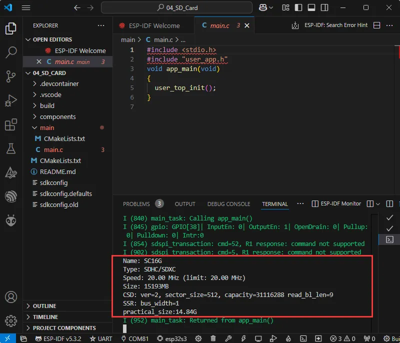
Click to open the Serial Monitor device. You can see the output TF card information; practical_size indicates the actual capacity of the TF card, as shown below:
05_WIFI_AP
Example Description
- Configure the board as an AP to wait for STA connections.
Hardware Connection
- Connect the board to the computer using a USB cable.
Code Analysis
wifi_init_softap(void): This function initializes the ESP32 Wi-Fi soft AP, including setting up the network interface, registering event handlers, configuring soft AP parameters, and starting the soft AP.
Expected Behavior
-
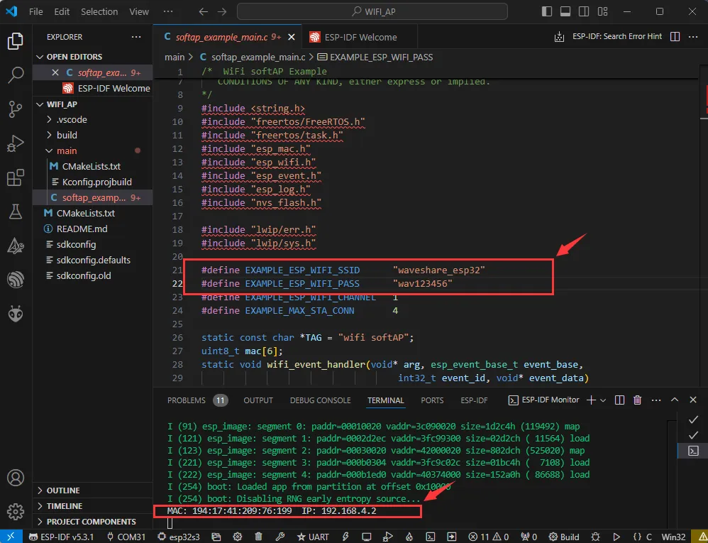
Use a phone or other device to connect to the Wi-Fi network named "bsp_esp_demo" with password "waveshare".
06_WIFI_STA
Example Description
- Configure the board as a STA to connect to an available AP. Upon successful connection, the acquired IP information is printed to the terminal.
Hardware Connection
- Connect the board to the computer using a USB cable.
Code Modification
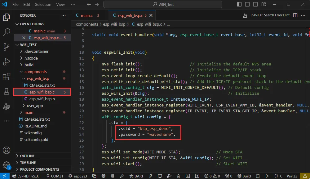
This example configures the chip in STA mode to connect to Wi-Fi and obtain an IP address. Before compiling and flashing the firmware, you need to modify the code to use a Wi-Fi router name and password available in your environment.
Code Analysis
wifi_init(void): This function initializes the Wi-Fi connection on the ESP32. It sets the ESP32 to Wi-Fi station mode and attempts to connect to the specified Wi-Fi network (via ssid and password). If successful, it prints the local IP address; if it fails to connect within a certain period (20 * 500 ms), it prints a connection failure message. At the same time, the function can also set the auto-connection and auto-reconnect functions.
Expected Behavior
-
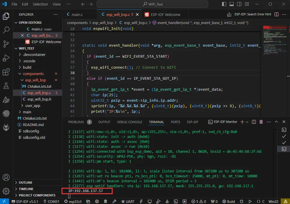
When the chip successfully connects to Wi-Fi in STA mode, open the serial monitor to see the acquired IP address.
07_LVGL-Test
Example Description
- By porting LVGL, a multi-functional GUI interface is displayed on the screen.
Hardware Connection
- Connect the board to the computer using a USB cable.
Code Analysis
For LVGL, lvgl_conf.h is its configuration file. Some common settings are described below. LVGL examples and file systems can also be configured in the conf file.
/*Color depth: 1 (1 byte per pixel), 8 (RGB332), 16 (RGB565), 32 (ARGB8888)*/
#define LV_COLOR_DEPTH 16//Color depth, a macro definition that must be concerned with porting LVGL

#define LV_MEM_CUSTOM 0
#if LV_MEM_CUSTOM == 0
    /*Size of the memory available for `lv_mem_alloc()` in bytes (>= 2kB)*/
    #define LV_MEM_SIZE (48U * 1024U)          /*[bytes]*/

    /*Set an address for the memory pool instead of allocating it as a normal array. Can be in external SRAM too.*/
    #define LV_MEM_ADR 0     /*0: unused*/
    /*Instead of an address give a memory allocator that will be called to get a memory pool for LVGL. E.g. my_malloc*/
    #if LV_MEM_ADR == 0
        #undef LV_MEM_POOL_INCLUDE
        #undef LV_MEM_POOL_ALLOC
    #endif

#else       /*LV_MEM_CUSTOM*/
    #define LV_MEM_CUSTOM_INCLUDE <stdlib.h>   /*Header for the dynamic memory function*/
    #define LV_MEM_CUSTOM_ALLOC   malloc
    #define LV_MEM_CUSTOM_FREE    free
    #define LV_MEM_CUSTOM_REALLOC realloc
#endif     /*LV_MEM_CUSTOM*/
//The above section is mainly for LVGL memory allocation,
//which defaults to lv_mem_alloc() versus lv_mem_free().
Code Modification
The display chip itself does not support hardware rotation. If rotation is needed, it can be done via software. In the lcd_bsp.c file, find the macro #define EXAMPLE_Rotate_90 and uncomment it. Note that software rotation requires an additional framebuffer copy, resulting in a lower frame rate compared to hardware rotation.
#define EXAMPLE_Rotate_90
Expected Behavior
-
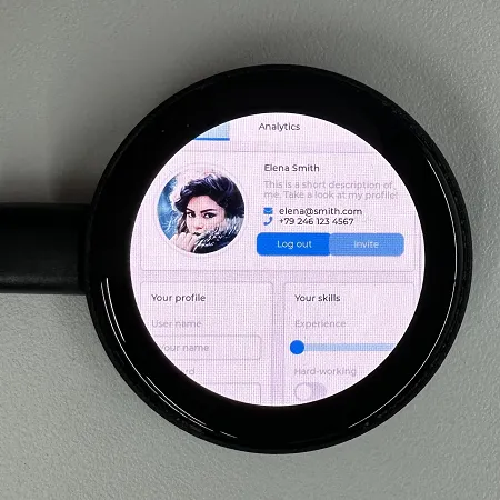
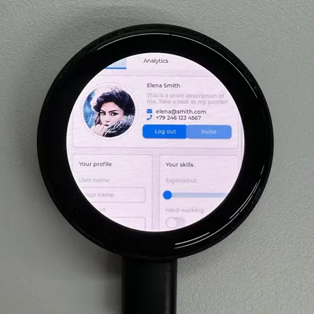
The LVGL example has high RAM and ROM requirements, so the environment must be configured as required. After the example is flashed, the running result of the device is as follows:
For more LVGL learning and usage, refer to the LVGL Official Documentation.
08_LVGL_SDIMG
Example Description
-
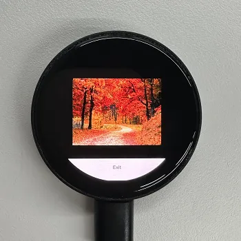
Store PNG, JPG, and BMP images on the TF card, then read the images from the TF card and display them on the LVGL interface.
Notes:
- Images must have a uniform resolution of 320 x 240.
- BMP images must be converted to RGB565 format.
Hardware Connection
- Connect the board to the computer using a USB cable.
Code Analysis
- The display chip itself does not support hardware rotation. If rotation is needed, it can be done via software. In the
mainfile, find the macro#define EXAMPLE_Rotate_90and uncomment it. Note that software rotation requires an additional framebuffer copy, resulting in a lower frame rate compared to hardware rotation.
#define EXAMPLE_Rotate_90
Expected Behavior
-
Create a directory named
Teston the TF card, place the desired images in it, insert the TF card into the board, and power it on. The device's expected behavior is as follows: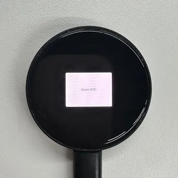
-
Clicking
Scan IMGwill scan for image files in the Test directory. The scan results are shown below: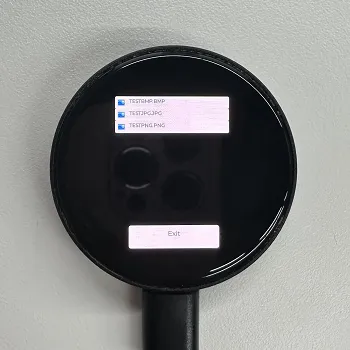
-
Clicking on a corresponding image file name will navigate to that image, as shown below:
09_FactoryProgram
Example Description
- This example is a comprehensive project that tests onboard features. Note the IDF version: V5.4.4 and above may not scan for surrounding Wi-Fi. If testing is required, compile with a lower IDF version or use the provided BIN firmware.
Hardware Connection
- Connect the board to your computer via USB cable. (The display effect defaults to a 90° software rotation. If not needed, find the
#define EXAMPLE_Rotate_90macro in themainfile and comment it out.)
Expected Behavior
-
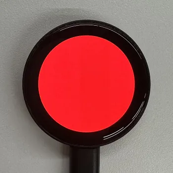
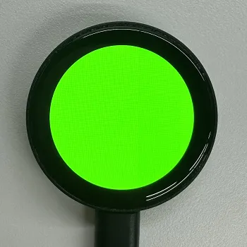
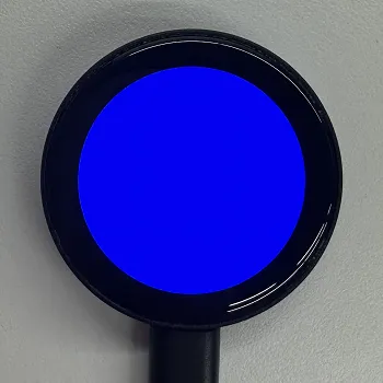
Swipe left or right to switch pages. First, RGB colors are displayed every 1.5 seconds, which allows you to check if the screen is working properly.
-
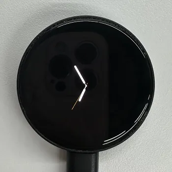
After displaying RGB, it will automatically jump to the clock interface.
-
Swipe left to see the page with onboard hardware information.
-
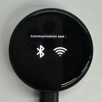
Swipe left again to see the function interface.
-
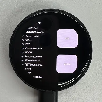
Click the Wi-Fi icon to enter the Wi-Fi test interface, then click the Scan button to scan for nearby Wi-Fi networks.
-
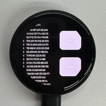
Click "Exit" to return to the previous interface, then click the BLE icon to enter the BLE test interface, and click the Scan button to scan for nearby BLE devices.
-
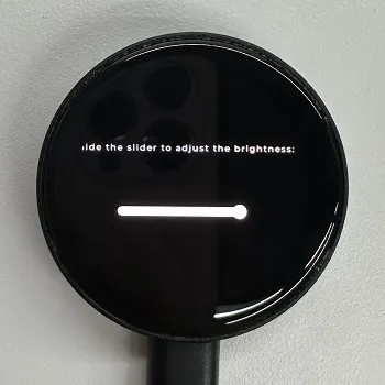
The final screen is for backlight adjustment, where you can slide the slider to adjust the backlight brightness.