ESP-IDF
This chapter contains the following sections. Please read as needed:
ESP-IDF Getting Started
New to ESP32 ESP-IDF development and looking to get started quickly? We have prepared a general Getting Started Tutorial for you.
- Section 1: Environment Setup
- Section 2: Running Examples
- Section 3: Creating a Project
- Section 4: Using Components
- Section 5: Debugging
- Section 6: FreeRTOS
- Section 7: Peripherals
- Section 8: Wi-Fi Programming
- Section 9: BLE Programming
Please Note: This tutorial uses the ESP32-S3-Zero as a teaching example, and all hardware code is based on its pinout. Before you start, it is recommended that you check the pinout of your development board to ensure the pin configuration is correct.
Setting Up Development Environment
The following guide uses Windows as an example, demonstrating development using VS Code + the ESP-IDF extension. macOS and Linux users should refer to the official documentation.
The screenshots in this section use ESP-IDF V5.5.2 as an example. When installing, please select the ESP-IDF version that matches your board's example.
Install the ESP-IDF Development Environment
-
Download the installation manager from the ESP-IDF Installation Manager page. This is Espressif's latest cross-platform installer. The following steps demonstrate how to use its offline installation feature.
Click the Offline Installer tab on the page, then select Windows as the operating system and the ESP-IDF version you need (the version shown in the screenshot is for reference only — choose the version that fits your actual needs).

After confirming your selection, click the download button. The browser will automatically download two files: the ESP-IDF Offline Package (.zst) and the ESP-IDF Installer (.exe).

Please wait for both files to finish downloading.
-
Once the download is complete, double-click to run the ESP-IDF Installer (eim-gui-windows-x64.exe).
The installer will automatically detect if the offline package exists in the same directory. Click Install from archive.

Next, select the installation path. We recommend using the default path. If you need to customize it, ensure the path does not contain Chinese characters or spaces. Click Start installation to proceed.

-
When you see the following screen, the ESP-IDF installation is successful.

-
We recommend installing the drivers as well. Click Finish installation, then select Install driver.

Install Visual Studio Code and the ESP-IDF Extension
-
Download and install Visual Studio Code.
-
During installation, it is recommended to check Add "Open with Code" action to Windows Explorer file context menu to facilitate opening project folders quickly.
-
In VS Code, click the Extensions icon
 in the Activity Bar on the side (or use the shortcut Ctrl + Shift + X) to open the Extensions view.
 -
Enter ESP-IDF in the search box, locate the ESP-IDF extension, and click Install.

-
For ESP-IDF extension versions ≥ 2.0, the extension will automatically detect and recognize the ESP-IDF environment installed in the previous steps, requiring no manual configuration.
Demo
The ESP-IDF demos are located in the ESP-IDF directory of the demo package.
| Demo | Basic Program Description | Dependency Library |
|---|---|---|
| 01_ADC_Test | Get the voltage value of the lithium battery | - |
| 02_WIFI_AP | Set to AP mode to obtain the IP address of the access device | - |
| 03_WIFI_STA | Set to STA mode to connect to Wi-Fi and obtain an IP address | - |
| 04_Audio_Test | Play the sound recorded by the microphone through the speaker | LVGL V9.5.0 |
| 05_LVGL_V8_Test | LVGLV8 demo | LVGL V8.3.11 |
| 06_LVGL_V9_Test | LVGLV9 demo | LVGL V9.5.0 |
| 07_FactoryProgram | Comprehensive demo | LVGL V9.5.0 |
01_ADC_Test
Demo Description
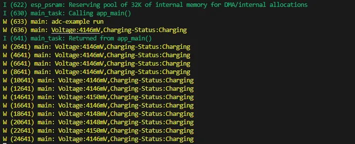
- The analog voltage connected through the GPIO is converted to digital by the ADC, and then the actual lithium battery voltage is calculated and printed to the terminal.
Hardware Connection
- Connect the board to the computer using a USB cable
Code Analysis
printf("adc-example run\n");             // Terminal output information
bsp_batt_init();                         // Initialize ADC channel
xTaskCreate(Batt_LoopTask, "Batt_LoopTask", 4 * 1024, NULL, 3, NULL); // Create a task to obtain voltage and battery charging information
Operation Result
-
After the program is compiled and uploaded, open the serial monitor to see the printed output of the lithium battery voltage and charging information, as shown in the following figure:
02_WIFI_AP
Demo Description
- This demo can set the development board as a hotspot, allowing phones or other devices in STA mode to connect to the development board.
Hardware Connection
- Connect the board to the computer using a USB cable
Code Analysis
-
In the file
softap_example_main.c, findSSIDandPASSWORD, and then your phone or other device in STA mode can use the SSID and PASSWORD to connect to the development board.#define EXAMPLE_ESP_WIFI_SSID "waveshare_esp32"#define EXAMPLE_ESP_WIFI_PASSWORD "wav123456"
Operation Result
-
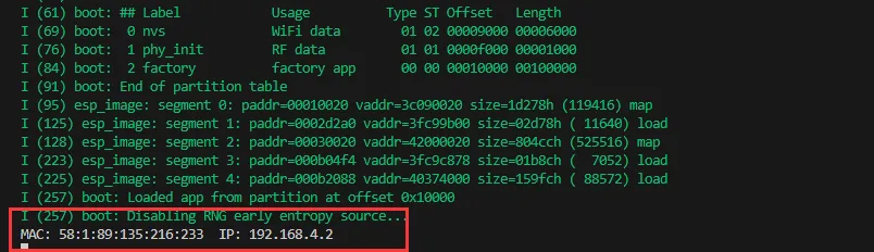
After flashing the program, open the Serial Terminal. If a device successfully connects to the hotspot, it will output the device's MAC address and IP address, as shown in the figure:
03_WIFI_STA
Demo Description
- This example configures the development board as a STA device to connect to a router, thereby accessing the system network.
Hardware Connection
- Connect the board to the computer using a USB cable
Code Analysis
-
In the file
esp_wifi_bsp.c, findssidandpassword, then modify them to the SSID and Password of an available router in your current environment.wifi_config_t wifi_config = {.sta = {.ssid = "PDCN",.password = "1234567890",},};
Operation Result
-
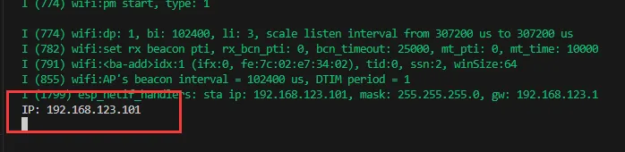
After flashing the program, open the Serial Terminal. If the device successfully connects to the hotspot, the obtained IP address will be output, as shown in the figure:
04_Audio_Test
Demo Description
- Demonstrate how to acquire microphone data, play music, and other functions.
Hardware Connection
- Connect the board to the computer using a USB cable
Code Analysis
bsp_broolesia_display_init();                             // Screen initialization
speaker = bsp_audio_codec_speaker_init();                 // Obtain playback handle
microphone = bsp_audio_codec_microphone_init();           // Obtain recording handle
boot_button_ = new Button(BUTTON_0_GPIO_PIN);Instantiate button
InitializeButtons();                                      // Button callback initialization
ESP_ERROR_CHECK(esp_codec_dev_open(speaker, &fs));        // Open playback
ESP_ERROR_CHECK(esp_codec_dev_open(microphone, &fs));     // Open recording
ESP_ERROR_CHECK(esp_codec_dev_set_out_vol(speaker, 100)); // Set playback volume
ESP_ERROR_CHECK(esp_codec_dev_set_in_gain(microphone,35));// Set recording gain
Operation Result
-
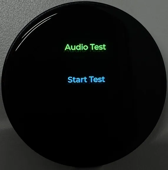
After the program is flashed, the screen displays as shown:
tip- Press the BOOT button once to record for 3 seconds; after recording ends, the recording is played back automatically.
- Double-click the BOOT button to play a piece of music; press and hold the BOOT button to interrupt playback.
05_LVGL_V8_Test
Demo Description
- Implements various multifunctional GUI interfaces on the screen by porting LVGL V8.
Hardware Connection
- Connect the board to the computer using a USB cable
Code Analysis
#define BACKLIGHT_EN 1               // Macro definition, enable backlight test, enabled by default
bsp_broolesia_display_init();        // Initialize screen and LVGL
if(bsp_display_lock(-1) == ESP_OK) { // Wait for lock
  lv_demo_widgets();                 // LVGL default UI
  bsp_display_unlock();              // Release lock
}
Operation Result
-
After the program is flashed, the device operation result is as follows:
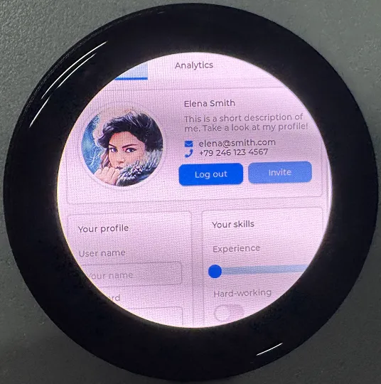
06_LVGL_V9_Test
Demo Description
- Implements various multifunctional GUI interfaces on the screen by porting LVGL V9.
Hardware Connection
- Connect the board to the computer using a USB cable
Code Analysis
#define BACKLIGHT_EN 1               // Macro definition, enable backlight test, enabled by default
bsp_broolesia_display_init();        // Initialize screen and LVGL
if(bsp_display_lock(-1) == ESP_OK) { // Wait for lock
  lv_demo_widgets();                 // LVGL default UI
  bsp_display_unlock();              // Release lock
}
Operation Result
-
After the program is flashed, the device operation result is as follows:

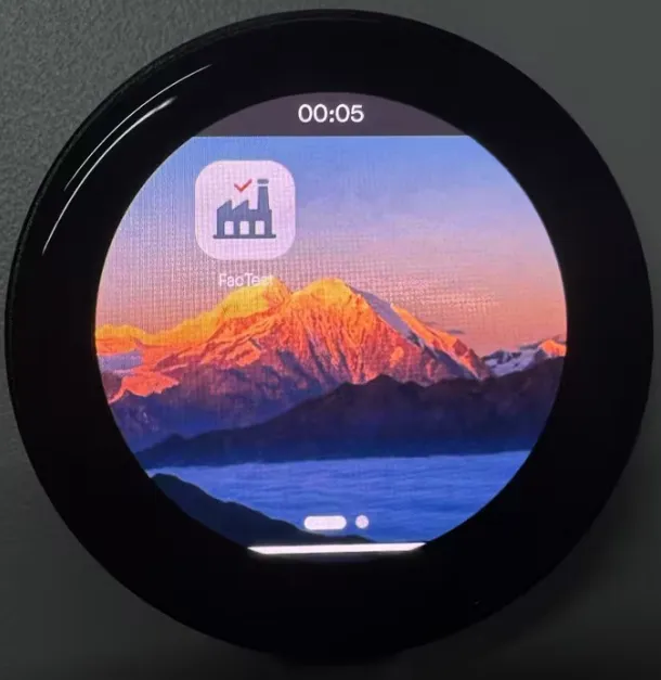
07_FactoryProgram
Demo Description
- Factory firmware. Users can flash the provided factory firmware to quickly get to know the development board.
Hardware Connection
- Connect the board to the computer using a USB cable
Operation Result
-
After flashing the factory firmware and restarting, the display on the development board will appear as shown below:
 tip
tip- FacTest app: Test onboard hardware, helps users quickly identify issues
- For more app development, follow the GitHub repository links; they will be continuously updated