Working with Arduino
This chapter contains the following sections. Please read as needed:
Arduino Getting Started
New to Arduino ESP32 development and looking for a quick start? We have prepared a comprehensive Getting Started Tutorial for you.
- Section 0: Getting to Know ESP32
- Section 1: Installing and Configuring Arduino IDE
- Section 2: Arduino Basics
- Section 3: Digital Output/Input
- Section 4: Analog Input
- Section 5: Pulse Width Modulation (PWM)
- Section 6: Serial Communication (UART)
- Section 7: I2C Communication
- Section 8: SPI Communication
- Section 9: Wi-Fi Basics
- Section 10: Web Server
- Section 11: Bluetooth
- Section 12: LVGL GUI Development
- Section 13: Comprehensive Project
Note: This tutorial uses the ESP32-S3-Zero as a reference example, and all hardware code is based on its pinout. Before you start, we recommend checking the pinout of your development board to ensure the pin configuration is correct.
Setting Up Development Environment
1. Installing and Configuring Arduino IDE
Please refer to the tutorial Installing and Configuring Arduino IDE to download and install the Arduino IDE and add ESP32 support.
| Board Name | Board Installation Requirement | Version Requirement |
|---|---|---|
| esp32 by Espressif Systems | "Install Offline" / "Install Online" | 3.1.0 |
2. Installing Libraries
- When installing Arduino libraries, there are typically two methods: Install Online and Install Offline. If the library installation requires Install Offline, you must use the provided library file.
- For most libraries, users can easily search for and install them via the Arduino IDE's online Library Manager. However, some open-source or custom libraries are not synchronized to the Arduino Library Manager and therefore cannot be found through online search. In this case, users can only install these libraries manually via offline methods.
- The sample program package for the ESP32-S3-Touch-AMOLED-1.75 development board can be downloaded from here. The
Arduino\librariesdirectory within the package already contains all the library files required for this tutorial.
| Library/File Name | Description | Version | Installation Method |
|---|---|---|---|
| GFX_Library_for_Arduino | GFX graphics library adapted for CO5300 | — | "Install Offline" |
| ESP32_IO_Expander | TCA9554 expander driver library | v0.0.3 | "Install Online" or "Install Offline" |
| LVGL | LVGL graphics library | v8.4.0 | After "online" installation, you need to copy the demos folder to src; "offline" installation is recommended |
| SensorLib | Driver library for PCF85063, QMI8658, CST9217 sensors | v0.3.1 | "Install Online" or "Install Offline" |
| XPowersLib | AXP2101 power management chip driver library | v0.2.6 | "Install Online" or "Install Offline" |
| Mylibrary | Development board pin macro definitions | —— | "Install Offline" |
| lv_conf.h | LVGL configuration file | —— | "Install Offline" |
There are strong dependencies between versions of LVGL and its driver libraries. For example, a driver written for LVGL v8 may not be compatible with LVGL v9. To ensure that the examples can be reproduced reliably, it is recommended to use the specific versions listed in the table above. Mixing different versions of libraries may lead to compilation failures or runtime errors.
3. Arduino Project Parameter Settings
Example
The Arduino examples are located in the Arduino/examples directory of the example package.
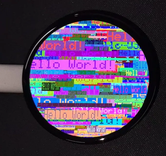
01_HelloWorld
Example Description
- This example demonstrates how to control the CO5300 display using the Arduino GFX library, demonstrating basic graphics library functions through dynamically changing text. This code can also be used to test the basic performance of the display and the random text display effects
Hardware Connection
- Connect the board to the computer using a USB cable
Code Analysis
-
Display initialization:
if (!gfx->begin()) {USBSerial.println("gfx->begin() failed!");} -
Clear the screen and display text:
gfx->fillScreen(BLACK);gfx->setCursor(10, 10);gfx->setTextColor(RED);gfx->println("Hello World!"); -
Animated display:
gfx->setCursor(random(gfx->width()), random(gfx->height()));gfx->setTextColor(random(0xffff), random(0xffff));gfx->setTextSize(random(6), random(6), random(2));gfx->println("Hello World!");
Operation Result
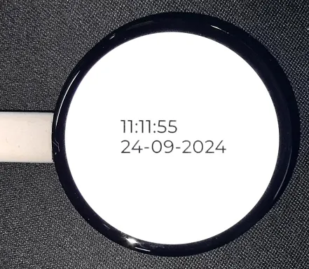
02_LVGL_PCF85063_simpleTime
Example Description
- This example demonstrates using the PCF85063 RTC module to display the current time on the CO5300 display under LVGL. It retrieves the time every second and updates the display only when the time changes, resulting in better time refresh effects
Hardware Connection
- Connect the board to the computer using a USB cable
Code Analysis
setup: Responsible for initializing various hardware devices and the LVGL graphics library environment- Serial initialization:
USBSerial.begin(115200)prepares for serial debugging - Real-time clock initialization: Attempts to initialize the real-time clock
rtc. If it fails, enters an infinite loop. Set the date and time - Touch controller initialization: Continuously attempts to initialize the touch controller
CST9217. If initialization fails, prints an error message and waits with a delay; prints a success message upon success - Graphics display initialization: Initializes the graphics display device
gfx, sets brightness, and prints LVGL and Arduino version information. Then initializes the LVGL, including registering a print callback function for debugging, initializing the display driver and the input device driver. Creates and starts an LVGL timer. Finally creates a label and sets its initial text to "Initializing..."
- Serial initialization:
looplv_timer_handler(): This is an important function in the LVGL graphics library, used to handle various timer events, animation updates, input processing, and other tasks for the graphical interface. Calling this function in each loop ensures the graphical interface runs smoothly and responds to interactions promptly- Time update and display: Gets the real-time clock time every second and prints it via the serial port. Then formats the time into a string and updates the text of the label to display the current time. Simultaneously sets the font of the label to a specific font. Finally adds a small delay
Operation Result
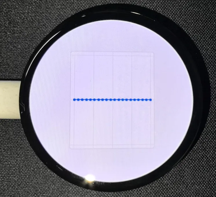
03_LVGL_QMI8658_ui
Example Description
- This example demonstrates using LVGL for graphical display, communicating with the QMI8658 IMU to obtain accelerometer and gyroscope data
Hardware Connection
- Connect the board to the computer using a USB cable
Code Analysis
setup: Responsible for initializing various hardware devices and the LVGL graphics library environment- Serial initialization:
USBSerial.begin(115200)prepares for serial debugging - Touch controller initialization: Continuously attempts to initialize the touch controller
CST9217. If initialization fails, prints an error message and waits with a delay; prints a success message upon success - Graphics display initialization: Initializes the graphics display device
gfx, sets brightness, and prints LVGL and Arduino version information. Then initializes the LVGL, including registering a print callback function for debugging, initializing the display driver and the input device driver. Creates and starts an LVGL timer. Finally creates a label and sets its initial text to "Initializing..." - Creating a chart: Creates a chart object
chart, sets chart properties such as type, range, number of data points, etc., and adds data series for the three axes of acceleration - Acceleration sensor initialization: Initializes the acceleration sensor
qmi, configures accelerometer and gyroscope parameters, enables them, and prints the chip ID and control register information
- Serial initialization:
looplv_timer_handler(): This is an important function in the LVGL graphics library, used to handle various timer events, animation updates, input processing, and other tasks for the graphical interface. Calling this function in each loop ensures the graphical interface runs smoothly and responds to interactions promptly- Reading acceleration sensor data: If acceleration sensor data is ready, reads acceleration data and prints it via the serial port, while updating the chart to display acceleration data. If the gyroscope data is ready, reads the gyroscope data and prints it via the serial port. Finally adds a small delay to increase data polling frequency
Operation Result
04_LVGL_AXP2101_ADC_Data
Example Description
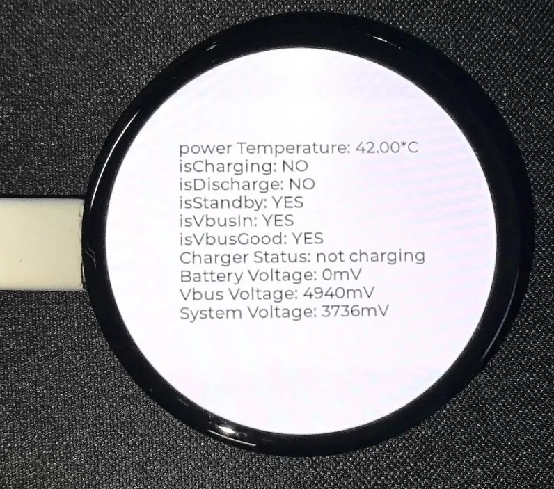
- This example demonstrates power management using the XPowers library under LVGL, and provides PWR custom button control for screen on and off actions
Hardware Connection
- Connect the board to the computer using a USB cable
Code Analysis
-
Screen on/off function
void toggleBacklight() {USBSerial.println(backlight_on);if (backlight_on) {for (int i = 255; i >= 0; i--) {gfx->Display_Brightness(i);delay(3);}}else{for(int i = 0;i <= 255;i++){gfx->Display_Brightness(i);delay(3);}}backlight_on = !backlight_on;}
Operation Result
- Displayed parameters: chip temperature, charging status, discharging status, standby status, Vbus connection, Vbus good status, charger status, battery voltage, Vbus voltage, system voltage, battery percentage.
05_LVGL_Widgets
Example Description
- This example demonstrates LVGL Widgets example. The frame rate can reach 50~60 fps in dynamic states. Optimizing the CO5300 display library can achieve smoother frame rates. This can be compared with scenarios where double buffering and dual acceleration are enabled in the ESP-IDF environment
Hardware Connection
- Connect the board to the computer using a USB cable
Code Analysis
setup: Responsible for initializing various hardware devices and the LVGL graphics library environment- Serial initialization:
USBSerial.begin(115200)prepares for serial debugging - I²C bus initialization:
Wire.begin(IIC_SDA, IIC_SCL);initializes the I²C bus for communication with other I²C devices. - Expansion chip initialization: Creates and initializes the expansion chip
expander, sets pin modes to output, and performs some initial pin state settings - Touch controller initialization: Continuously attempts to initialize the touch controller
CST9217. If initialization fails, prints an error message and waits with a delay; prints a success message upon success - Graphics display initialization: Initializes the graphics display device
gfx, sets brightness, and obtains the width and height of the screen. Then initializes LVGL, including registering a print callback function for debugging, setting the touch controller's power mode to monitoring mode, initializing display driver and input device driver. Creates and starts an LVGL timer. Creates a label and sets its text. Finally callslv_demo_widgets()to showcase LVGL example widgets
- Serial initialization:
looplv_timer_handler(): This is an important function in the LVGL graphics library, used to handle various timer events, animation updates, input processing, and other tasks for the graphical interface. Calling this function in each loop ensures the graphical interface runs smoothly and responds to interactions promptlydelay(5);: Adds a small delay to avoid excessive CPU resource consumption
Operation Result

06_LVGL_SD_Test
Example Description
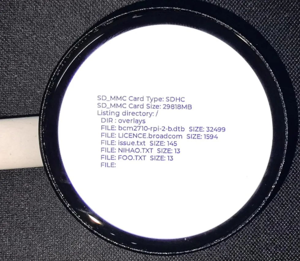
- This example demonstrates using SDMMC to drive a TF card and output its contents to the display
Hardware Connection
- Connect the board to the computer using a USB cable
- Insert the TF card into the board
Code Analysis
setup: Responsible for initializing various hardware devices and the LVGL graphics library environment- Serial initialization:
USBSerial.begin(115200)prepares for serial debugging - I²C bus and expander initialization: Initializes the I²C bus, creates and initializes the expander chip, sets its pin modes to output, and prints the initial state and new state.
- Graphics display initialization: Initializes the graphics display device, sets brightness, initializes LVGL, sets the display driver and input device driver, creates and starts the LVGL timer.
- TF card Initialization and information display: Sets the pins of the TF card and attempts to mount the TF card. If the mount fails, an error message is displayed on the serial port and the screen. If the mount is successful, detect the TF card type and display it, get the TF card size and display it. Then call the
listDirfunction to list the contents of the TF card root directory, and display the TF card type, size, and directory listing information on a label on the screen. listDir: Recursively lists files and subdirectories under a specified directory.- First prints the directory name being listed. Then open the specified directory, and if the opening fails, an error message will be returned. If it is not a directory that is opened, an error message is also returned. If it is a directory, then traverse the files and subdirectories in it. For subdirectories, recursively calls the
listDirfunction to continue listing their contents. For files, prints the file name and file size. Finally, return all collected information as a string
- First prints the directory name being listed. Then open the specified directory, and if the opening fails, an error message will be returned. If it is not a directory that is opened, an error message is also returned. If it is a directory, then traverse the files and subdirectories in it. For subdirectories, recursively calls the
Operation Result
07_ES8311
Example Description
- This example demonstrates using I2S to drive the ES8311 chip, playing the converted binary audio file
Hardware Connection
- Connect the board to the computer using a USB cable
Code Analysis
es8311_codec_init: Initializes the ES8311 audio codec- Creates an ES8311 codec handle
es_handle - Configures ES8311 clock parameters, including master clock and sampling clock frequencies, clock polarity, etc.
- Initializes the codec, sets audio resolution to 16-bit
- Configures sampling frequency
- Configures microphone-related parameters, such as turning off the microphone, setting volume and microphone gain
- Creates an ES8311 codec handle
setup: Performs overall initialization settings, including serial port, pins, I2S, and the ES8311 codec- Initializesserial port for debugging output
- Sets a specific pin as output and pulls it high
- Configures the I2S bus, setting pins, operating mode, sample rate, data bit width, channel mode, etc.
- Initializes the I2C bus
- Calls
es8311_codec_initfunction to initialize the ES8311 codec - Plays a predefined audio data (
canon_pcm) via the I2S bus
Operation Result
- The device will play auido directly without showing content on the screen
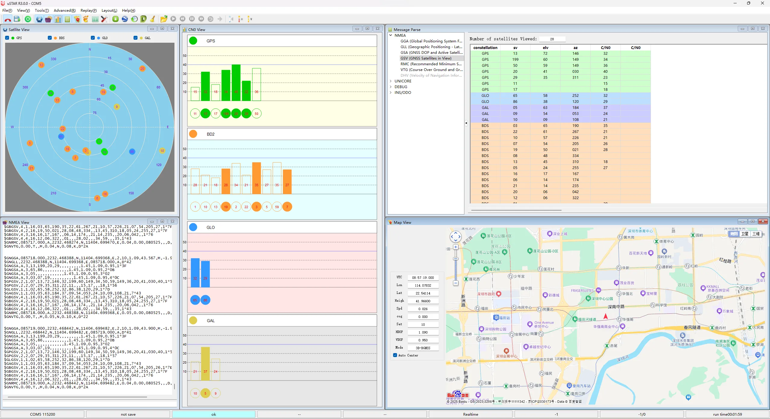
08_ESP32-S3-LCD76G-I2C
Example Description
- This example demonstrates actively querying the LC76G for NMEA data using I2C. The transmitted data is printed to the serial port, allowing direct use of an NMEA parsing tool to obtain information such as latitude and longitude.
- When using, you need to enable "USB CDC On Boot".
Hardware Connection
- Connect the board to the computer using a USB cable
- Connect a GPS ceramic antenna
Operation Result