ESP-IDF
This chapter contains the following sections. Please read as needed:
ESP-IDF Getting Started
New to ESP32 ESP-IDF development and looking to get started quickly? We have prepared a general Getting Started Tutorial for you.
- Section 1: Environment Setup
- Section 2: Running Examples
- Section 3: Creating a Project
- Section 4: Using Components
- Section 5: Debugging
- Section 6: FreeRTOS
- Section 7: Peripherals
- Section 8: Wi-Fi Programming
- Section 9: BLE Programming
Please Note: This tutorial uses the ESP32-S3-Zero as a teaching example, and all hardware code is based on its pinout. Before you start, it is recommended that you check the pinout of your development board to ensure the pin configuration is correct.
Setting Up Development Environment
For the ESP32-S3-Touch-AMOLED-1.8 development board, ESP-IDF V5.3.1 and above is required.
The following guide uses Windows as an example, demonstrating development using VS Code + the ESP-IDF extension. macOS and Linux users should refer to the official documentation.
The screenshots in this section use ESP-IDF V5.5.2 as an example. When installing, please select the ESP-IDF version that matches your board's example.
Install the ESP-IDF Development Environment
-
Download the installation manager from the ESP-IDF Installation Manager page. This is Espressif's latest cross-platform installer. The following steps demonstrate how to use its offline installation feature.
Click the Offline Installer tab on the page, then select Windows as the operating system and the ESP-IDF version you need (the version shown in the screenshot is for reference only — choose the version that fits your actual needs).

After confirming your selection, click the download button. The browser will automatically download two files: the ESP-IDF Offline Package (.zst) and the ESP-IDF Installer (.exe).

Please wait for both files to finish downloading.
-
Once the download is complete, double-click to run the ESP-IDF Installer (eim-gui-windows-x64.exe).
The installer will automatically detect if the offline package exists in the same directory. Click Install from archive.

Next, select the installation path. We recommend using the default path. If you need to customize it, ensure the path does not contain Chinese characters or spaces. Click Start installation to proceed.

-
When you see the following screen, the ESP-IDF installation is successful.

-
We recommend installing the drivers as well. Click Finish installation, then select Install driver.

Install Visual Studio Code and the ESP-IDF Extension
-
Download and install Visual Studio Code.
-
During installation, it is recommended to check Add "Open with Code" action to Windows Explorer file context menu to facilitate opening project folders quickly.
-
In VS Code, click the Extensions icon
 in the Activity Bar on the side (or use the shortcut Ctrl + Shift + X) to open the Extensions view.
 -
Enter ESP-IDF in the search box, locate the ESP-IDF extension, and click Install.

-
For ESP-IDF extension versions ≥ 2.0, the extension will automatically detect and recognize the ESP-IDF environment installed in the previous steps, requiring no manual configuration.
Example
The ESP-IDF examples are located in the ESP-IDF directory of the example package.
| Example | Basic Description |
|---|---|
| 01_AXP2101 | Drive AXP2101 via the ported XPowersLib to obtain power-related data |
| 02_PCF85063 | Drive pcf85063 for time storage and reading |
| 03_QMI8658 | Drive qmi8658 via the ported SensorLib to obtain gyroscope-related data |
| 04_SD_MMC | Initialize TF card using sdmmc and read/write content |
| 05_LVGL_WITH_RAM | Run LVGL example with double buffering, DMA acceleration, and tear-free mode |
| 06_I2SCodec | Use I2S to drive the ES8311 Codec chip for audio capture or playback |
01_AXP2101
Example Description
- This example demonstrates porting XPowersLib in ESP-IDF, and driving AXP2101 to obtain power-related data through the ported XPowersLib
Hardware Connection
- Connect the board to the computer using a USB cable
Code Analysis
i2c_init: Initializes the I2C master device, preparing it for communication with other devices (e.g., the PMU)- Configures I2C parameters, including setting the master device mode, specifying the SDA and SCL pins, enabling the pull-up resistor, and determining the clock frequency
- Installs the I2C driver to apply the configuration to the actual hardware
pmu_register_read: Reads a series of byte data from a specific register of the PMU- Performs parameter checks to ensure the incoming parameters are valid and avoid invalid read operations
- Performs I2C operations in two steps, first sends the register address to read, then reads the data During the reading process, different processing is carried out according to the length of bytes to be read to ensure accurate reading of the data. At the same time, handles error cases in the I2C communication process and returns the corresponding status code so that the upper-layer code can determine if the read operation is successful
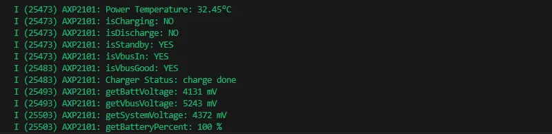
Operation Result
- This example will not light up the screen
- The serial port monitor displays the parameters: chip temperature, charging state, discharging state, standby state, Vbus connection, Vbus condition, charger status, battery voltage, Vbus voltage, system voltage, battery percentage
02_PCF85063
Example Description
- This example uses a simple approach to drive the pcf85063 for time storage and reading.
Hardware Connection
- Connect the board to the computer using a USB cable
Code Analysis
i2c_master_init- Defines an I2C configuration structure
conf, setting master mode, SDA/SCL pins, pull-up resistors, and clock frequency. - Uses
i2c_param_configto configure I2C parameters. If the configuration fails, an error log is recorded and an error code is returned. - Uses
i2c_driver_installto install the I2C driver, applying the configuration to the hardware, and returns the result.
- Defines an I2C configuration structure
rtc_get_time- Defines a 7-byte array
datato store the read time data. - Calls
rtc_read_regto read 7 bytes of time data from RTC register address 0x04. If the reading fails, an error log is recorded and an error code is returned - Processes the time data read, separately extract the seconds, minutes, hours, days, weeks, months, and years, and convert BCD to decimal.
- Uses
ESP_LOGIto output the formatted current time.
- Defines a 7-byte array
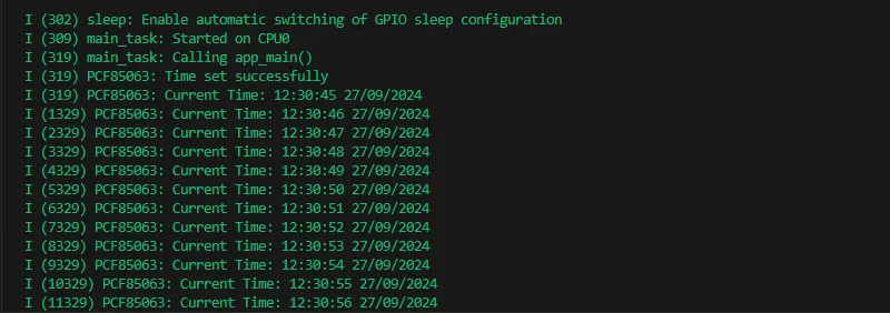
Operation Result
- This example will not light up the screen
- The serial port monitor prints time information
03_QMI8658
Example Description
- This example demonstrates porting SensorLib in ESP-IDF, then using the ported SensorLib to drive qmi8658 to obtain gyroscope-related data.
Hardware Connection
- Connect the board to the computer using a USB cable
Code Analysis
setup_sensor: Sets up and initializes the environment and parameters needed to communicate with the QMI8658 sensor.- Initializes I2C communication to ensure that the connection channel to the sensor is established
- Initializes the sensor, check if the sensor is properly connected
- Configures the sensor's accelerometer and gyroscope parameters to meet specific application needs
- Enables the sensor to start collecting data
read_sensor_data: In a continuous loop, reads data from the QMI8658 sensor, processes it, and outputs it.- In the loop, continuously checks if the sensor data is ready
- When the data is ready, the accelerometer, gyroscope, timestamp, and temperature data are read and logged out
- Handles the failure of data reading by recording an error log for troubleshooting
- Controls the execution speed of the loop through delay to avoid excessive consumption of system resources
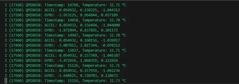
Operation Result
- This example will not light up the screen
- The serial port monitor prints sensor data
04_SD_MMC
Example Description
- This example demonstrates initializing a TF card using sdmmc and reading/writing content.
Hardware Connection
- Connect the board to the computer using a USB cable
Code Analysis
esp_vfs_fat_sdmmc_mount: Mounts the FAT filesystem of the TF card to a specified mount point, establishing a file access interface to the TF card.- Prepares mount configuration, determining parameters such as whether to format on mount failure.
- Initializes SDMMC host configuration, including frequency, etc. For specific chips, power control initialization may also be required
- Configures SDMMC slot parameters, such as bus width and GPIO pin settings.
- Calls the function to perform the mount operation, attempting to initialize the TF card and mount the filesystem. If successful, you can get the TF card information; if it fails, an error code is returned for error handling
s_example_write_file: Writes data to a file at the specified path, used to create and update file content on the TF card.- Opens the file at the specified path in write mode; if opening fails, logs an error and returns an error code.
- Uses the standard C library function
fprintfto write data to the file. - Closes the file and logs that the file has been written. If there are issues while opening or writing, it will affect the creation of the file and the saving of data
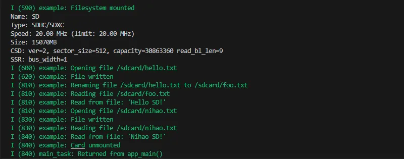
Operation Result
- This example will not light up the screen
- The Serial Monitor prints TF card information.
05_LVGL_WITH_RAM
Example Description
- This example demonstrates an LVGL example, running the LVGL example with double buffering, DMA acceleration, and tear-free mode. It can smoothly display dynamic graphics and text, achieving a frame rate of 200–300 fps.
Hardware Connection
- Connect the board to the computer using a USB cable
Code Analysis
app_main: The initialization and startup flow of the entire application.- Hardware initialization: Configures and initializes hardware devices related to LCD display and touch input (if available), such as GPIO pins, SPI bus, I2C bus, LCD panel driver, and touch controller driver, etc.
- LVGL initialization: Initializes the LVGL library, allocates drawing buffers, registers display driver and touch input device driver (if available), installs timers, and creates smutexes and starts LVGL tasks
- Example display: Finally shows LVGL examples, such as widget examples, etc.
example_lvgl_port_task: LVGL task function, responsible for handling LVGL timed updates and task delay control to ensure smooth operation of the LVGL interface.- Timed update: In the task loop, obtains the mutex and calls
lv_timer_handlerto process LVGL timer events, updating the interface state. - Delay control: Determine the task's delay time based on the results of timer processing to avoid excessive CPU resource usage and ensure timely response to LVGL events
- Timed update: In the task loop, obtains the mutex and calls
Operation Result
 | 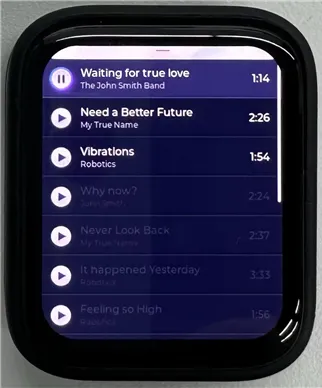 |
|---|
06_I2SCodec
Example Description
- This example demonstrates using the I2S to drive the ES8311 Codec chip for audio capture or playback.
Hardware Connection
- Connect the board to the computer using a USB cable
Code Analysis
app_main: The initialization and startup flow of the entire application.- Initializes GPIO, sets a specific pin as output mode, and controls its level state.
- Prints startup information, providing initial feedback on program operation.
- Initializes the I2S peripheral, configures I2S channels and related hardware parameters to ensure audio data transmission.
- Initializes the ES8311 codec by configuring the I2C bus and setting codec parameters, preparing for audio processing.
- Creates corresponding tasks based on different operating modes to implement music playback or microphone echo functions.
es8311_codec_init: Responsible for initializing the I2C peripheral and configuring the ES8311 audio codec, ensuring the codec works properly.- Initializes the I2C bus, including setting pins, mode, clock speed, etc., and installs the I2C driver, establishing the foundation for communication with the ES8311.
- Creates an ES8311 codec handle for subsequent configuration operations.
- Configures ES8311 clock parameters, such as master and slave clock inversion states, master clock source, frequency, and sampling frequency.
- Initializes the ES8311 codec, setting parameters such as audio resolution.
- Sets sampling frequency, volume, and microphone parameters (as needed) to meet specific audio processing requirements.
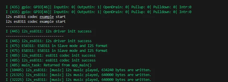
Operation Result
- This example does not light up the screen, only plays audio.
- The Serial Monitor can be used to view print information.
Custom Audio
Users can customize audio playback segments by following the steps below (some programming knowledge is required)
- Select any format of music you want to play (e.g. a.mp3)
- Install the
ffmpegtool - Use the command line to view detailed information about the audio file, including encoding format, duration, bitrate, and audio stream details.
ffprobe a.mp3
- Cut your music because there is not enough space to hold the entire song
ffmpeg -i a.mp3 -ss 00:00:00 -t 00:00:20 a_cut.mp3
- Convert music format to .pcm
ffmpeg -i a_cut.mp3 -f s16le -ar 16000 -ac 1 -acodec pcm_s16le a_cut.pcm
- Move the trimmed
a_cut.pcmaudio file to themaindirectory - Replace
canon.pcmwitha_cut.pcminmain\CMakeList.txt - Replace
_binary_canon_pcm_startand_binary_canon_pcm_endwith_binary_a_cut_pcm_startand_binary_a_cut_pcm_endinmain\i2s_es8311_example.cCompile and flash