ESP32-S3-Touch-AMOLED-2.06
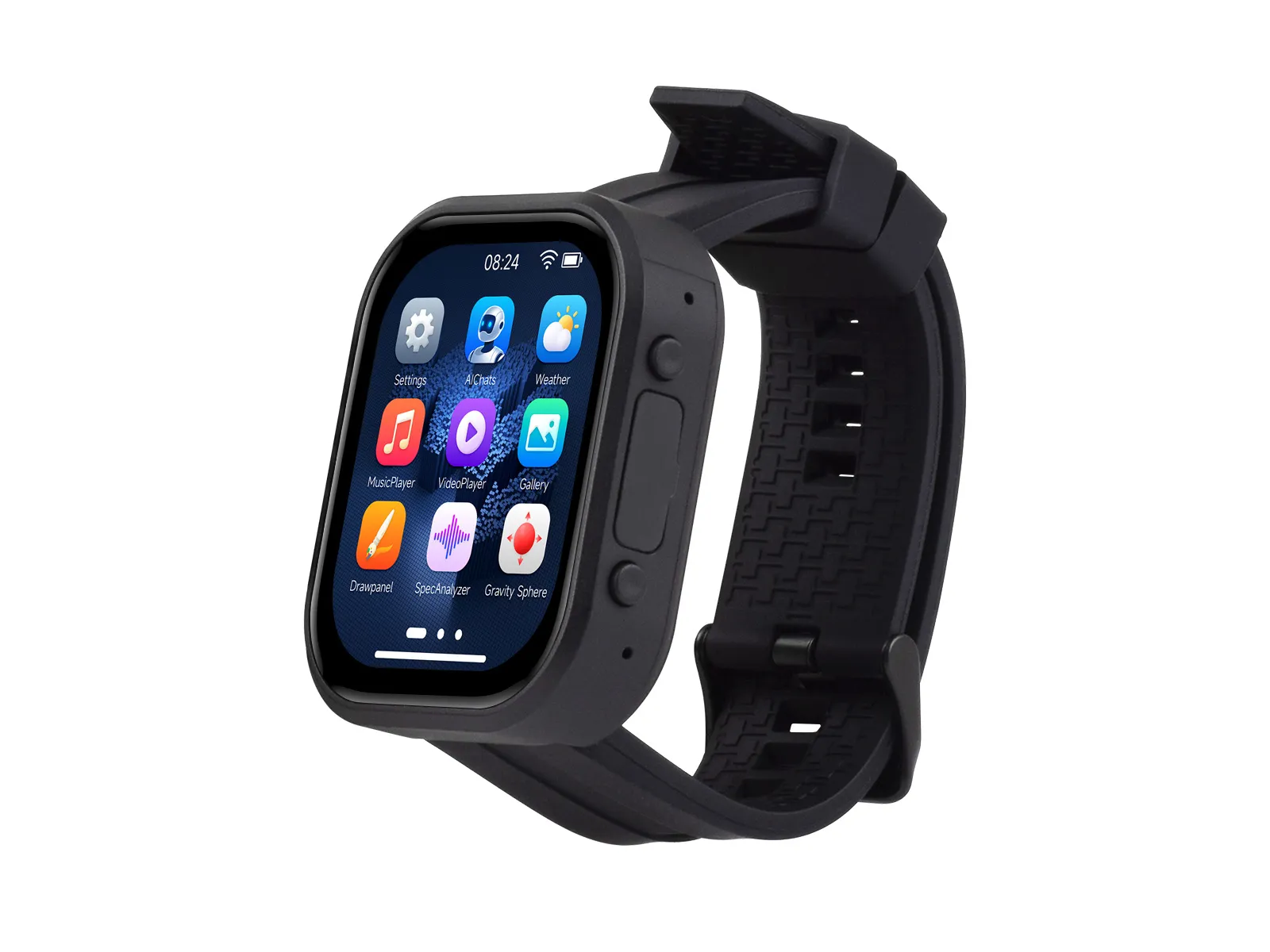
The ESP32-S3-Touch-AMOLED-2.06 is a high-performance, wearable watch-style development board designed by Waveshare. Based on the ESP32-S3R8 microcontroller, it integrates a 2.06inch capacitive touch AMOLED display, a 6-axis IMU, an RTC, an audio codec, power management, and a TF card slot. It comes with a custom case and a detachable strap, making it ideal for wearable device prototyping, functional verification, and interactive application development.
If you are looking for:
- Accelerating development with AI tools: Share this page link with AI tools to help them accurately understand the board hardware and generate usable code.
- Developing with Arduino IDE: See Working with Arduino
- Developing with ESP-IDF: See Working with ESP-IDF
- Downloading schematics, datasheets, and example code: See Related Resources
- Having issues: See Product FAQ or contact Technical Support
| SKU | Product |
|---|---|
| 31957 | ESP32-S3-Touch-AMOLED-2.06 |
| 31958 | ESP32-S3-Touch-AMOLED-2.06-EN |
Development Board Battery Assembly Guide
When disassembling, pay special attention to the cable area. The connection in this part is fragile. Pulling, twisting, or applying excessive force can easily cause breakage and affect device operation. Before disassembly, understand the importance of cable protection. During disassembly, move slowly and gently. When separating the enclosure from the motherboard, observe the location and routing of the cable connections. Support the motherboard or cable to keep it in a natural, tension-free state to avoid forced dismantling.
Features
- Onboard 2.06inch capacitive touch high‑definition AMOLED screen with 410 × 502 resolution and 16.7 million colors, capable of displaying colorful images clearly
- Built-in CO5300 driver chip and FT3168 capacitive touch controller chip, communicating via QSPI and I2C interfaces respectively, minimizing the use of I/O pins
- Onboard QMI8658 six-axis inertial measurement unit (3-axis accelerometer, 3-axis gyroscope) for motion posture detection, step counting, etc.
- Onboard PCF85063 RTC chip, powered by the AXP2101 with battery backup for uninterrupted operation
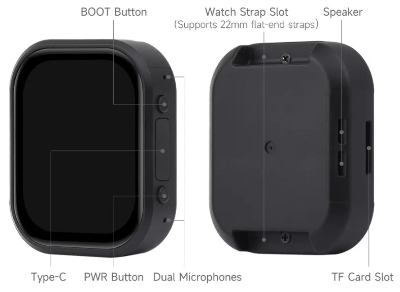
- Onboard PWR and BOOT side buttons, configurable for custom function development
- Onboard 3.7V MX1.25 lithium battery charge/discharge interface
- Onboard TF card slot, providing expanded storage, fast data transfer, and flexibility, suitable for data logging and media playback, simplifying circuit design
- Benefits of using the AXP2101 include efficient power management, support for multiple output voltages, charging, and battery management functions.
- The AMOLED screen offers higher contrast, wide viewing angles, rich colors, fast response time, slim design, low power consumption, and flexibility
- Power supply and charging via Type-C; 3.7 V MX1.25 lithium battery interface.
- Peripheral pads reserved for I2C, UART, and USB.
Peripheral Quick Reference
| Peripheral | Device / Function | Interface | GPIO / Signal | Description |
|---|---|---|---|---|
| Main Controller | ESP32-S3R8 | - | - | 8 MB PSRAM, 32 MB Flash; supports Wi-Fi and Bluetooth LE |
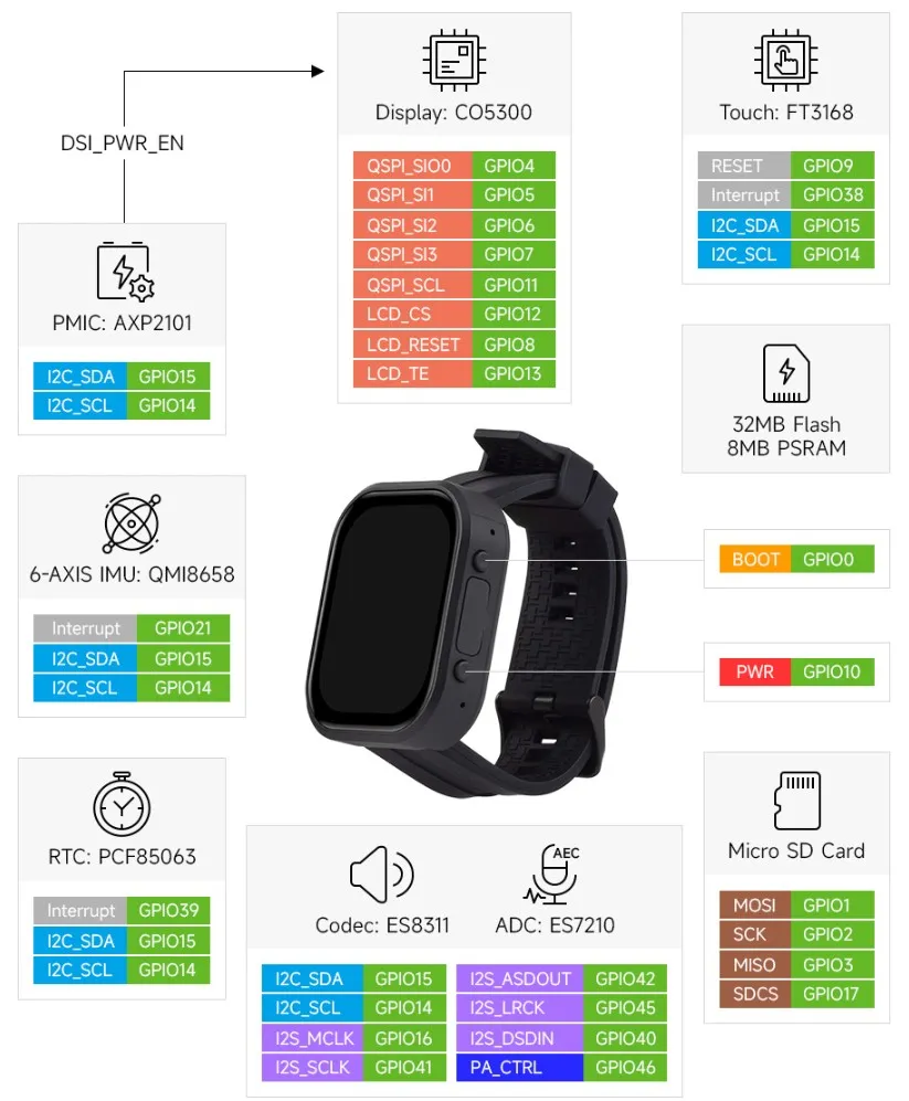
| AMOLED Display | CO5300 Driver, 2.06inch 410 × 502 AMOLED | QSPI | GPIO4/5/6/7 (SIO0-3), GPIO11 (SCL), GPIO12 (CS), GPIO8 (RESET), GPIO13 (TE) | Dedicated QSPI bus for the display |
| Touch | FT3168 | I2C + INT + RESET | GPIO14 (SCL), GPIO15 (SDA), GPIO38 (TP_INT), GPIO9 (TP_RESET) | I2C bus shared with multiple onboard devices |
| Power Management | AXP2101 | I2C | GPIO14 (ESP32_SCL), GPIO15 (ESP32_SDA) | Manages power, charging, and lithium battery management; PWR button controls power state |
| IMU | QMI8658C, 6-axis (Accelerometer + Gyroscope) | I2C + INT | GPIO14/15 (I2C), GPIO21 (QMI_INT1) | Used for posture, motion gestures, and step counting |
| RTC | PCF85063ATL | I2C + INT | GPIO14 (RTC_SCL), GPIO15 (RTC_SDA), GPIO39 (RTC_INT) | RTC interrupt connected to GPIO39 |
| TF | TF Card Slot | TF SPI | GPIO1 (MOSI), GPIO2 (SCK), GPIO3 (MISO), GPIO17 (SDCS) | Used for logs, media, and file storage |
| Audio Codec | ES8311 | I2C + I2S | GPIO14/15 (I2C), GPIO16 (MCLK), GPIO40 (I2S_DSDIN), GPIO41 (I2S_SCLK), GPIO45 (I2S_LRCK) | Audio playback chain; GPIO46 used for amplifier control |
| Microphone ADC | ES7210 | I2C + I2S | GPIO14/15 (I2C), GPIO16 (MCLK), GPIO41 (I2S_SCLK), GPIO42 (I2S_ASDOUT), GPIO45 (I2S_LRCK) | Dual-microphone audio capture chain |
| Amplifier & Speaker | NS4150B | GPIO | GPIO46 (PA_CTRL) | Controls speaker amplifier enable |
| Native USB | USB D- / D+ | USB | GPIO19 (USB_N), GPIO20 (USB_P) | Used for Type-C USB communication, downloading, and debugging |
| Debug UART | UART0 | UART | GPIO43 (U0TXD), GPIO44 (U0RXD) | Brought out via reserved pads |
| System & Buttons | BOOT, PWR, SYS_OUT | GPIO / PMU | GPIO0 (BOOT), GPIO10 (SYS_OUT / PWR power control related) | GPIO0 is the boot configuration pin; the operational state of PWR can be detected via GPIO10 |
Pinout Definition
GPIO Assignments
| GPIO | Signal / Function | Connection & Description |
|---|---|---|
GPIO0 | BOOT | Download mode and BOOT button detection; low level indicates pressed. Boot configuration pin; not recommended for fixed peripheral assignment |
GPIO1 | SD_MOSI | TF card data output / CMD |
GPIO2 | SD_SCK | TF card clock |
GPIO3 | SD_MISO | TF card data input / D0 |
GPIO4 | QSPI_SIO0 | CO5300 display data line 0 |
GPIO5 | QSPI_SIO1 | CO5300 display data line 1 |
GPIO6 | QSPI_SIO2 | CO5300 display data line 2 |
GPIO7 | QSPI_SIO3 | CO5300 display data line 3 |
GPIO8 | LCD_RESET | AMOLED display reset |
GPIO9 | TP_RESET | FT3168 touch reset |
GPIO10 | SYS_OUT | Related to PWR power control / button state circuit; high level indicates PWR pressed during operation |
GPIO11 | QSPI_SCL | CO5300 display QSPI clock |
GPIO12 | LCD_CS | CO5300 display chip select |
GPIO13 | LCD_TE | Display Tearing Effect (TE) synchronization signal |
GPIO14 | ESP32_SCL / TP_SCL / RTC_SCL | Shared onboard I2C SCL, connects to touch, AXP2101, QMI8658C, PCF85063ATL, ES8311, and ES7210 |
GPIO15 | ESP32_SDA / TP_SDA / RTC_SDA | Shared onboard I2C SDA, connects to touch, AXP2101, QMI8658C, PCF85063ATL, ES8311, and ES7210 |
GPIO16 | I2S_MCLK | Shared I2S master clock for ES8311 and ES7210 |
GPIO17 | SDCS | TF card chip select |
GPIO19 | USB_N | ESP32-S3 native USB D- |
GPIO20 | USB_P | ESP32-S3 native USB D+ |
GPIO21 | QMI_INT1 | QMI8658C IMU interrupt |
GPIO38 | TP_INT | FT3168 touch interrupt |
GPIO39 | RTC_INT | PCF85063ATL RTC interrupt |
GPIO40 | I2S_DSDIN | I2S playback data from ESP32-S3 to ES8311 |
GPIO41 | I2S_SCLK | Shared I2S bit clock for ES8311 and ES7210 |
GPIO42 | I2S_ASDOUT | I2S capture data from ES7210 to ESP32-S3 |
GPIO43 | U0TXD | UART0 transmit; reserved debug pad |
GPIO44 | U0RXD | UART0 receive; reserved debug pad |
GPIO45 | I2S_LRCK | Shared I2S left/right channel clock for ES8311 and ES7210 |
GPIO46 | PA_CTRL | NS4150B speaker amplifier control |
Reserved Debug Pads
| Signal | Corresponding GPIO / Power | Use |
|---|---|---|
U0TXD | GPIO43 | UART0 debug transmit |
U0RXD | GPIO44 | UART0 debug receive |
ESP32_SCL | GPIO14 | Shared I2C clock |
ESP32_SDA | GPIO15 | Shared I2C data |
USB'_N | GPIO19 | Native USB D- |
USB'_P | GPIO20 | Native USB D+ |
VBUS, VCC3V3, GND | Power | Peripheral power supply and debug reference |
Usage Limitations and Multiplexing Notes
GPIO14andGPIO15are the shared onboard I2C bus. External devices must avoid address conflicts with existing devices and ensure bus voltage level compatibility.GPIO19andGPIO20are the native USB data lines; multiplexing them will affect USB downloading, communication, and debugging.GPIO43andGPIO44are UART0, typically used for logging and debugging. Please confirm your debugging requirements before occupying them.GPIO0is the boot configuration pin and is also connected to the BOOT button. It should not be used as a fixed pin for general peripherals.- Display, touch, audio, TF, IMU, and RTC use the GPIOs listed in the table. Before starting secondary development, please confirm whether the corresponding functions need to be disabled or used in conjunction with the existing drivers.
Button Description
| Button | Function |
|---|---|
| BOOT | Long-press and power on to enter download mode, suitable for recovery when the program is abnormal or USB/GPIO is occupied. During normal operation, the button state can be read via GPIO0; a low level indicates it is pressed. |
| PWR | Long-press for about 6 seconds to power off while the device is on. Single-click to power on when the device is off (charging is still possible while off). During normal operation, the button state can be read via GPIO10; a high level indicates it is pressed. Long-pressing for more than about 6 seconds will trigger a shutdown. |
Development Methods
The ESP32-S3-Touch-AMOLED-2.06 supports both the Arduino IDE and ESP‑IDF development frameworks, giving developers flexible options. You can choose the development tool that best suits your project needs and personal preferences.
Arduino is generally easier to get started with and more beginner‑friendly for hobbyists. ESP‑IDF offers a more complete development toolchain and finer‑grained system control, making it suitable for complex projects or applications with higher performance requirements.
-
Arduino IDE is a convenient, flexible, and easy-to-use open-source electronics prototyping platform. It requires minimal foundational knowledge, allowing for rapid development after a short learning period. Arduino has a huge global user community, providing a vast amount of open-source code, project examples, and tutorials, as well as a rich library ecosystem that encapsulates complex functions, enabling developers to implement various features rapidly. You can refer to the Working with Arduino to complete the initial setup, and the tutorial also provides related example programs for reference.
-
ESP-IDF, short for Espressif IoT Development Framework, is a professional development framework launched by Espressif Systems for its ESP series of chips. It is based on C language development and includes compilers, debuggers, flashing tools, etc. It supports development via command line or integrated development environments (such as Visual Studio Code with the Espressif IDF plugin), which provides features like code navigation, project management, and debugging. We recommend using VS Code for development. For the specific configuration process, please refer to the Working with ESP-IDF. The tutorial also provides relevant example programs for reference.