Working with Arduino
This chapter contains the following sections. Please read as needed:
Before running the examples, please ensure the following conditions are met:
- The ESP32-S3-Touch-AMOLED-2.16 development board is ready.
- The board is connected to your computer via a USB data cable.
- Arduino IDE is installed.
- The ESP32 Arduino Core is installed. The example directory for this page is
Arduino-v3.3.5. It is recommended to use the Arduino-ESP32 version that matches the example package. - The product example package has been downloaded.
- The library files in the
librariesdirectory have been installed as required by the example package.
Arduino Getting Started
New to Arduino ESP32 development and looking for a quick start? We have prepared a comprehensive Getting Started Tutorial for you.
- Section 0: Getting to Know ESP32
- Section 1: Installing and Configuring Arduino IDE
- Section 2: Arduino Basics
- Section 3: Digital Output/Input
- Section 4: Analog Input
- Section 5: Pulse Width Modulation (PWM)
- Section 6: Serial Communication (UART)
- Section 7: I2C Communication
- Section 8: SPI Communication
- Section 9: Wi-Fi Basics
- Section 10: Web Server
- Section 11: Bluetooth
- Section 12: LVGL GUI Development
- Section 13: Comprehensive Project
Note: This tutorial uses the ESP32-S3-Zero as a reference example, and all hardware code is based on its pinout. Before you start, we recommend checking the pinout of your development board to ensure the pin configuration is correct.
Setting Up the Development Environment
1. Installing and Configuring the Arduino IDE
Please refer to the tutorial Installing and Configuring Arduino IDE to download and install the Arduino IDE and add ESP32 support.
2. Installing Libraries
| Library or File | Purpose | Recommended Version or Notes | Installation Method |
|---|---|---|---|
GFX Library for Arduino | Display driver and basic graphics drawing | v1.6.4 | Library Manager or manual installation |
SensorLib | Sensor drivers such as PCF85063, QMI8658 | v0.3.3 | Library Manager or manual installation |
XPowersLib | Driver for AXP2101 power management chip | v0.2.6 | Library Manager or manual installation |
lvgl | LVGL graphics framework | v8.4.0 | Library Manager or manual installation |
Mylibrary | Development board pin macro definitions | Provided in the example package | Manual installation |
lv_conf.h | LVGL configuration file | Provided in the example package | Manual installation |
The APIs of LVGL v8 and LVGL v9 are significantly different. The current Arduino examples use the LVGL v8 style interface, for example:
lv_disp_drv_t
lv_disp_draw_buf_t
lv_disp_drv_register()
If LVGL v9 is installed by mistake, numerous compilation errors may occur. It is strongly recommended to strictly use the library versions provided in the example package.
Recommended installation steps:
-
Download the product example package.
-
Locate:
examples/Arduino-v3.3.5/libraries -
Copy the library folders under this directory to the Arduino libraries folder.
The default libraries folder path on Windows is usually:
C:\Users\<username>\Documents\Arduino\librariesYou can also find the
Sketchbook locationviaFile > Preferencesin the Arduino IDE; thelibrariesfolder under that path is the libraries directory. -
Library installation verification
After installation, it is recommended to verify:
- The directories
GFX_Library_for_Arduino,SensorLib,XPowersLib,lvgl, etc., are visible underDocuments\Arduino\libraries. lv_conf.his placed where the Arduino compiler can find it.- Restart the Arduino IDE before compiling examples.
- Do not keep multiple different versions of
lvgl,XPowersLiborGFX_Library_for_Arduinosimultaneously, to avoid header conflicts.
- The directories
Example
The Arduino examples are located in the Arduino/examples directory of the example package.
| Example | Basic Description | Dependency Library |
|---|---|---|
| 01_HelloWorld | Demonstrates the basic graphics library function and can also be used to test the basic performance of display screens and the display effect of random text | GFX_Library_for_Arduino |
| 02_GFX_AsciiTable | Prints ASCII characters in rows and columns on the screen according to the screen size | GFX_Library_for_Arduino |
| 03_LVGL_AXP2101_ADC_Data | Drives the AXP2101 using the ported XPowersLib to get power-related data | GFX_Library_for_Arduino |
| 04_LVGL_QMI8658_ui | LVGL draws an acceleration line chart | LVGL, SensorLib |
| 05_LVGL_Widgets | LVGL demonstration | LVGL, Arduino_DriveBus, Adafruit_XCA9554 |
| 06_ES7210 | ES7210 driver example, picking up human voice for detection | —— |
| 07_ES8311 | ES8311 driver example, plays simple audio | —— |
1. Directory Structure
The current Arduino examples directory contains the following projects:
examples/Arduino-v3.3.5/examples
├── 01_HelloWorld
├── 02_GFX_AsciiTable
├── 03_LVGL_AXP2101_ADC_Data
├── 04_LVGL_QMI8658_ui
├── 05_LVGL_Widgets
├── 06_ES7210
└── 07_ES8311
Each subdirectory is an independent Arduino example. To open an example, open the .ino file inside that directory, for example:
examples/Arduino-v3.3.5/examples/01_HelloWorld/01_HelloWorld.ino
Some audio examples also contain additional driver or audio data files:
06_ES7210
├── 06_ES7210.ino
├── audio_hal.h
├── es7210.cpp
└── es7210.h

07_ES8311
├── 07_ES8311.ino
├── canon.h
├── es8311.c
├── es8311.h
└── es8311_reg.h
Recommended First-Run Order
It is recommended to run the examples in the following order:
01_HelloWorld
  ↓
02_GFX_AsciiTable
  ↓
03_LVGL_AXP2101_ADC_Data
  ↓
04_LVGL_QMI8658_ui
  ↓
05_LVGL_Widgets
  ↓
06_ES7210
  ↓
07_ES8311
- Use
01_HelloWorldfirst to verify basic display functionality. - Then use
02_GFX_AsciiTableto verify character drawing, coordinates, and display orientation. - Next use
03_LVGL_AXP2101_ADC_Datato verify the PMU, power data, and basic LVGL display. - Then use
04_LVGL_QMI8658_uito verify IMU data reading and LVGL chart updates. - Then use
05_LVGL_Widgetsto verify touch, LVGL example, screen rotation, and larger memory usage. - Finally run
06_ES7210and07_ES8311to verify audio input and audio playback.
2. Example Descriptions
01_HelloWorld
Function Description
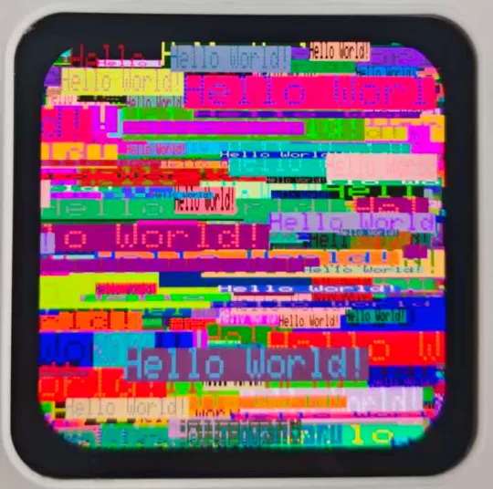
This example uses the Arduino GFX library to initialize the AMOLED display and randomly displays Hello World! text on the screen.
Main functions:
- Initialize QSPI display bus.
- Initialize the
Arduino_CO5300display object. - Set screen orientation register.
- Clear screen.
- Set brightness.
- Draw random text.
Code Entry
01_HelloWorld/01_HelloWorld.ino
Recommended key code sections:
| Code | Purpose |
|---|---|
Arduino_ESP32QSPI | Creates QSPI display bus |
Arduino_CO5300 | Creates display driver object |
gfx->begin() | Initializes the display |
bus->writeC8D8(0x36, 0xA0) | Sets display orientation or scanning parameters |
gfx->setBrightness(128) | Sets screen brightness |
gfx->println("Hello World!") | Draws text |
Normal Operation
The screen first displays a line of red Hello World!. Then the screen will randomly display Hello World! with different colors and sizes at random positions. The serial port will periodically output:
loop
Troubleshooting
| Symptom | Possible Cause | Suggested Action |
|---|---|---|
Arduino_GFX_Library.h not found during compilation | GFX library not installed or wrong path | Check if GFX_Library_for_Arduino is in Arduino libraries directory |
| No display on screen | Board configuration, display driver, or power issue | Check the board, PSRAM, library version; reinstall libraries from the example package if necessary |
| No serial output | Wrong serial port or baud rate | Select correct port; set serial monitor to 115200 |
| Incorrect display orientation | Display orientation register or screen parameters modified | Restore original example code and test |
02_GFX_AsciiTable
Function Description
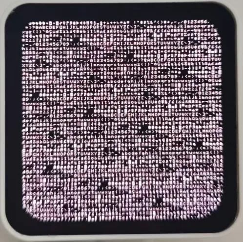
This example uses the Arduino GFX library to draw an ASCII character table on the display. It is more suitable than 01_HelloWorld for checking screen coordinates, character drawing, row/column arrangement, and display orientation.
Main functions:
- Calculate number of rows and columns based on screen width and height.
- Draw row and column headers.
- Draw ASCII characters one by one.
Code Entry
02_GFX_AsciiTable/02_GFX_AsciiTable.ino
Recommended key code sections:
| Code | Purpose |
|---|---|
numCols = LCD_WIDTH / 8 | Calculate number of columns based on character width |
numRows = LCD_HEIGHT / 10 | Calculate number of rows based on character height |
gfx->drawChar(...) | Draw a single character |
gfx->setTextColor(...) | Set character color |
Normal Operation
The screen displays an ASCII character table with row and column headers at the top and left. This example does not continuously refresh in loop(); the displayed image remains unchanged after completion.
Troubleshooting
| Symptom | Possible Cause | Suggested Action |
|---|---|---|
| Character table extends beyond screen | Incorrect screen width/height macro definitions | Check LCD_WIDTH and LCD_HEIGHT in pin_config.h |
| Incorrect character orientation | Display orientation configuration mismatch | Check if bus->writeC8D8(0x36, 0xA0) has been modified |
| Compilation fails | Incompatible GFX library version | Use the library from the example package or official recommended version |
03_LVGL_AXP2101_ADC_Data
Function Description
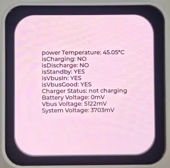
This example uses XPowersLib to drive the AXP2101 PMU and displays power-related data on the screen using LVGL.
Main displayed data includes:
- PMU temperature
- Charging status (charging or not)
- Discharging status (discharging or not)
- Standby status
- VBUS present
- VBUS good
- Charging state
- Battery voltage
- VBUS voltage
- System voltage
- Battery percentage
Code Entry
03_LVGL_AXP2101_ADC_Data/03_LVGL_AXP2101_ADC_Data.ino
Recommended key code sections:
| Function or Code | Purpose |
|---|---|
power.begin(...) | Initializes AXP2101 |
adcOn() | Enables temperature, battery, VBUS, system voltage detection |
adcOff() | Disables ADC detection |
my_disp_flush() | LVGL flush callback |
lv_disp_drv_register() | Registers LVGL display driver |
lv_label_set_text(info_label, info.c_str()) | Updates power information on screen |
Normal Operation
The screen displays power status information including temperature, battery voltage, VBUS voltage, system voltage, and charging state. The serial port outputs LVGL version and initialization complete information.
If PMU initialization fails, the serial port outputs:
PMU is not online...
Troubleshooting
| Symptom | Possible Cause | Suggested Action |
|---|---|---|
Displays PMU is not online... | I2C communication failure with AXP2101 | Check I2C pins, pin_config.h, library version |
XPowersLib.h not found during compilation | XPowersLib not installed | Install XPowersLib from the example package |
| LVGL compilation errors | LVGL version mismatch | Use LVGL v8.4.0, do not use LVGL v9 |
| Garbled or abnormal display | LVGL configuration or color format mismatch | Check lv_conf.h and LV_COLOR_16_SWAP |
04_LVGL_QMI8658_ui
Function Description
This example uses SensorLib to read accelerometer and gyroscope data from the QMI8658 IMU, and uses an LVGL chart to display real-time X/Y/Z acceleration curves.
Main functions:
- Initialize display and LVGL.
- Initialize QMI8658.
- Configure accelerometer range and output data rate.
- Output accelerometer and gyroscope data to serial port.
- Display acceleration curves using LVGL Chart on the screen.
Code Entry
04_LVGL_QMI8658_ui/04_LVGL_QMI8658_ui.ino
Recommended key code sections:
| Code | Purpose |
|---|---|
qmi.begin(...) | Initializes QMI8658 |
qmi.configAccelerometer(...) | Configures accelerometer |
qmi.enableAccelerometer() | Enables accelerometer |
lv_chart_create(...) | Creates chart |
lv_chart_add_series(...) | Adds X/Y/Z curves |
lv_chart_set_next_value(...) | Updates chart data |
Normal Operation
The screen displays a line chart. When the board is moved or tilted, the three acceleration curves (red, green, blue) will change. The serial port outputs something like:
{ACCEL: x,y,z}
{GYRO: x,y,z}

If QMI8658 initialization fails, the serial port outputs:
Failed to find QMI8658 - check your wiring!
Troubleshooting
| Symptom | Possible Cause | Suggested Action |
|---|---|---|
| QMI8658 initialization fails | I2C address or pin configuration error | Check QMI8658_L_SLAVE_ADDRESS and IIC_SDA/IIC_SCL |
| Chart does not refresh | LVGL timer or lv_timer_handler() not running | Ensure loop() remains in lv_timer_handler() |
| Serial data present but no chart | LVGL display driver issue | Run 03_LVGL_AXP2101_ADC_Data first to verify LVGL |
| Curves do not change | Board stationary or sensor not enabled | Move the board, check qmi.enableAccelerometer() |
05_LVGL_Widgets
Function Description
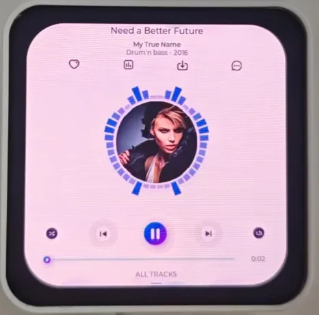
This example is a more complete LVGL demonstration, including touch controller, IMU orientation detection, screen rotation, and LVGL demo. The current code defaults to running:
lv_demo_music();
Other demos are commented in the code:
// lv_demo_widgets();
// lv_demo_benchmark();
// lv_demo_keypad_encoder();
// lv_demo_stress();
Code Entry
05_LVGL_Widgets/05_LVGL_Widgets.ino
Recommended key code sections:
| Code | Purpose |
|---|---|
HWCDC USBSerial | Uses USB CDC serial output |
touch.begin(...) | Initializes touch controller |
attachInterrupt(TP_INT, ...) | Registers touch interrupt |
my_touchpad_read(...) | LVGL touch read callback |
heap_caps_malloc(..., MALLOC_CAP_DMA) | Allocates DMA buffer for LVGL display flushing |
lv_disp_set_rotation(...) | Rotates screen based on IMU orientation |
lv_demo_music() | Starts LVGL music demo |
Normal Operation
The screen displays the LVGL Music demo. Touching the screen will output touch coordinates to the serial port, e.g.:
Data x ...
Data y ...
When the board is tilted, the screen orientation automatically switches based on IMU data. After successful initialization, the serial port outputs information about LVGL and Arduino.
Usage Notes
- This example relies more on memory than previous examples. Enable PSRAM.
- This example uses
USBSerial. It is recommended to enableUSB CDC On Boot. - If the serial monitor shows no output, make sure you have selected the correct USB CDC serial port.
- If compilation indicates insufficient memory or the program is too large, select a larger Partition Scheme.
Troubleshooting
| Symptom | Possible Cause | Suggested Action |
|---|---|---|
| Compilation fails, LVGL API not found | LVGL v9 installed | Use LVGL v8.4.0 |
| Black screen or reboot | PSRAM not enabled or insufficient memory | Enable PSRAM, select a large APP partition |
| Touch not responding | Touch initialization failure or interrupt not triggered | Check if touch is not online... is output, verify TP_RST/TP_INT |
| No serial output | USB CDC not enabled or wrong port selected | Enable USB CDC On Boot, reselect Port |
| Screen rotation abnormal | IMU data or rotation threshold inappropriate | Run 04_LVGL_QMI8658_ui first to verify IMU |
06_ES7210
Function Description
This example uses I2S to drive the ES7210 audio ADC, captures microphone audio, and uses VAD for voice activity detection. This example does not display anything on the screen; results are judged via the serial port.
Main functions:
- Initialize ES7210.
- Configure I2S input.
- Set microphone gain.
- Create VAD instance.
- Read audio data and detect voice activity.
Code Entry
06_ES7210/06_ES7210.ino
Related driver files:
06_ES7210/es7210.cpp
06_ES7210/es7210.h
06_ES7210/audio_hal.h
Recommended key code sections:
| Code | Purpose |
|---|---|
es7210_adc_init(...) | Initializes ES7210 |
es7210_adc_config_i2s(...) | Configures ES7210 I2S |
es7210_adc_set_gain(...) | Sets microphone gain |
i2s_driver_install(...) | Installs I2S driver |
i2s_read(...) | Reads audio samples |
vad_process(...) | Voice activity detection |
Normal Operation
No change on screen. The serial port outputs PSRAM and Flash sizes. When speaking into the microphone or making voice sounds, the serial port should output:
Speech detected
Troubleshooting
| Symptom | Possible Cause | Suggested Action |
|---|---|---|
| No screen activity | This example does not use the screen by design | Check serial port for proper operation |
No Speech detected | Input volume too low or microphone gain inappropriate | Speak close to the microphone, check gain configuration |
esp_vad.h not found during compilation | Arduino-ESP32 version or component mismatch | Use the Arduino-v3.3.5 environment matching the example package |
| I2S read error | I2S pin configuration or ES7210 initialization error | Check ES7210 pin definitions in pin_config.h |
07_ES8311
Function Description
This example uses the ES8311 audio codec to play built-in audio data, and then in subsequent loops reads input audio and writes it back to output, implementing a simple audio loopback.
Main functions:
- Initialize I2S.
- Initialize ES8311.
- Enable amplifier control pin.
- Play built-in PCM audio from
canon.h. - In
loop(), read audio and write it back.
Code Entry
07_ES8311/07_ES8311.ino
Related files:
07_ES8311/es8311.c
07_ES8311/es8311.h
07_ES8311/es8311_reg.h
07_ES8311/canon.h
Recommended key code sections:
| Code | Purpose |
|---|---|
i2s.setPins(...) | Configures I2S pins |
i2s.begin(...) | Starts I2S |
Wire.begin(IIC_SDA, IIC_SCL) | Initializes I2C |
digitalWrite(PA, HIGH) | Enables amplifier control |
es8311_codec_init() | Initializes ES8311 |
i2s.write((uint8_t *)canon_pcm, canon_pcm_len) | Plays built-in audio |
i2s.readBytes(...) | Reads audio input |
Normal Operation
No change on screen. The development board should play built-in audio. The serial port outputs:
[echo] Echo start
Then enters the audio loopback logic. If read or write fails, the serial port outputs:
[echo] i2s read failed
[echo] i2s write failed
Troubleshooting
| Symptom | Possible Cause | Suggested Action |
|---|---|---|
| No sound | Amplifier not enabled, volume too low, speaker connection issue | Check PA pin, volume, external audio device |
| Slow compilation or large file | Built-in PCM data in canon.h is large | Normal behavior |
| Program too large to upload | Partition too small | Select a larger Partition Scheme |
| I2S initialization fails | Pin or Arduino Core mismatch | Check definitions of I2S_BCK_IO, I2S_WS_IO, I2S_DO_IO, etc. |