ESP32-S3-Touch-LCD-1.46
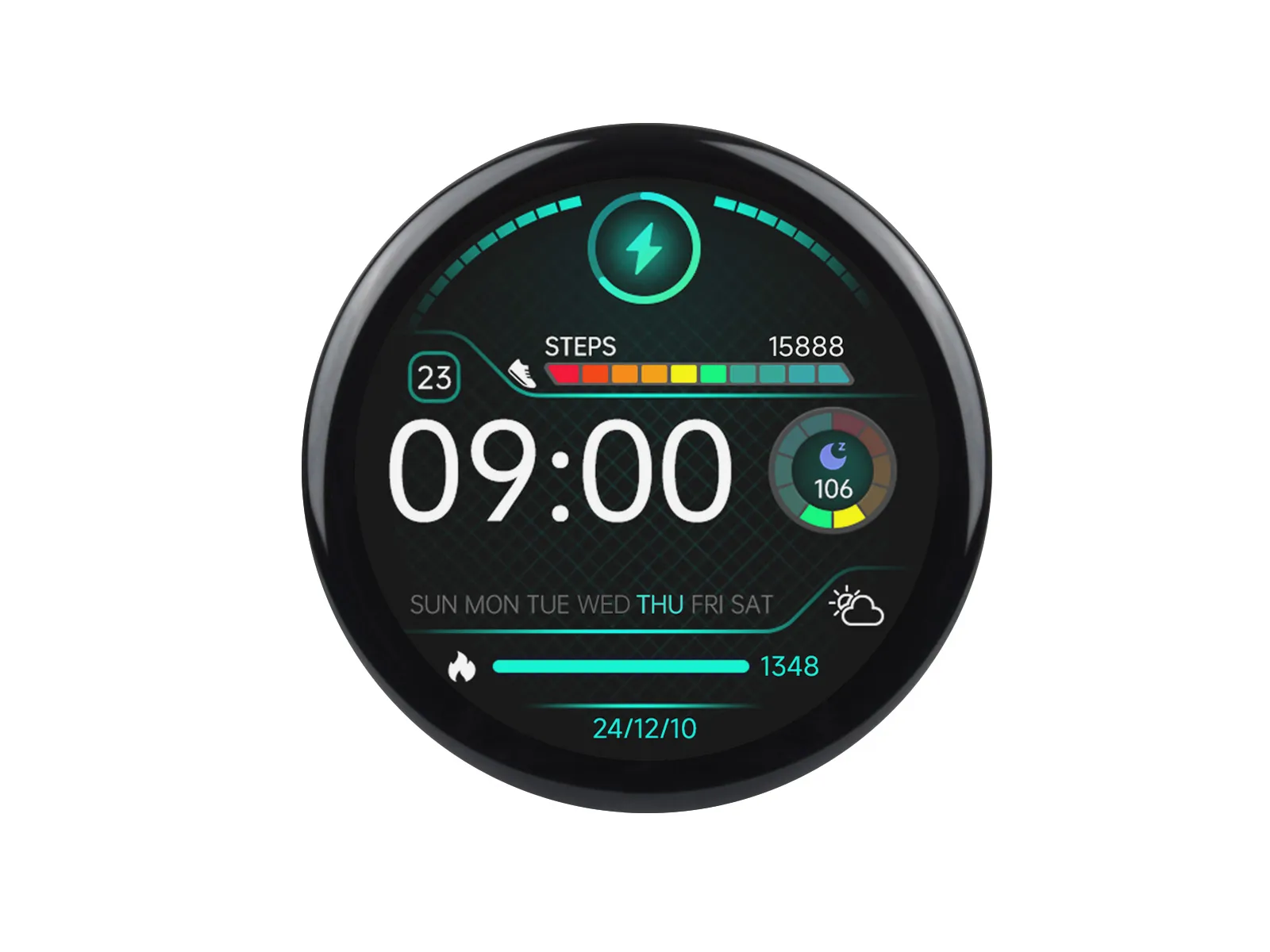
The ESP32-S3-Touch-LCD-1.46 is a microcontroller development board that supports 2.4GHz Wi‑Fi and Bluetooth BLE 5. It integrates a large capacity of Flash and PSRAM, and features an onboard 1.46inch touch LCD screen that can smoothly run GUI interface programs such as LVGL. Combined with various peripheral interfaces, it enables rapid development of HMI and other applications based on the ESP32-S3.
| SKU | Product |
|---|---|
| 29565 | ESP32-S3-Touch-LCD-1.46 |
| 29564 | ESP32-S3-Touch-LCD-1.46B |
| 33837 | ESP32-S3-Touch-LCD-1.46C |
Features
- Powered by the ESP32-S3R8 high-performance Xtensa 32-bit LX7 dual-core processor, with a main frequency of up to 240 MHz
- Supports 2.4 GHz Wi‑Fi (802.11 b/g/n) and Bluetooth 5 (LE) with an onboard antenna
- Built-in 512 KB SRAM and 384 KB ROM, with 8 MB PSRAM stacked and onboard 16 MB Flash (supports connecting external expansion devices)
- Type-C interface for improved user convenience and device compatibility
- Onboard 1.46inch LCD screen with 412 × 412 resolution and 16.7 million colors
- Supports I2C touch control with interrupt
- Exposes UART, I2C, and some I/O interfaces
- Onboard QMI8658 6-axis IMU (3-axis accelerometer and 3-axis gyroscope) enables motion posture detection, step counting, and other functions
- Onboard PCF85063 RTC chip with uninterrupted power supply through an external battery, ensuring the RTC function operates during main battery replacement
- Onboard PWR and BOOT two side buttons with customizable functions, allowing for custom function development
- Onboard 3.7V MX1.25 lithium battery charge/discharge interface
- Onboard TF card slot for expanded storage and fast data transfer, offering flexibility for data logging and media playback, simplifying circuit design
- Supports precise control of flexible clock and multiple power modes for low-power applications across various scenarios
- Multiple GPIO pins are brought out and can be mapped to various functional interfaces for custom development
Specifications
| Parameter | Value |
|---|---|
| Interface | USB Type‑C |
| Main Controller | ESP32-S3 |
| Screen Type | TFT |
| Screen Controller | Display: SPD2010 Touch: SPD2010 |
| Onboard Devices | Motion sensor: QMI8658 RTC clock: PCF85063 PCM audio decoder: PCM5101 MIC TF card slot Speaker Battery charging management module |
| Mounting Screws | M2 |
Onboard Resources
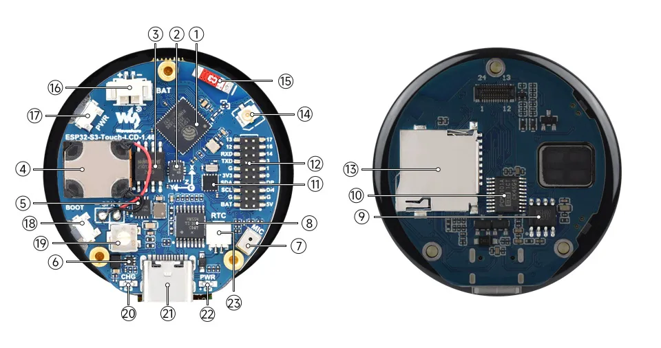
- ESP32-S3R8 Dual-core processor, operating frequency up to 240MHz
- QST attitude sensor QMI8658 (6-axis IMU includes a 3-axis gyroscope and a 3-axis accelerometer)
- 16MB Flash
- Speaker
- Battery charging management chip
- MP1605GTF-Z Power module, supports up to 2A (MAX) output
- Microphone
- TCA9554PWR GPIO expander chip
- Power amplifier chip
- PCM5101 audio decoder chip
- RTC chip PCF85063 RTC clock
- Multi‑function header brings out multiple GPIOs
- TF card slot Allows connection of high-capacity TF cards
- IPEX1 connector Switching to use the external antenna via resoldering an onboard resistor
- Onboard ceramic antenna
- Battery header MX1.25 2PIN connector for 3.7V lithium battery, supports charging and discharging
- Battery power control button Used with software support
- BOOT button
- Volume adjustment knob
- Charging indicator When a system battery is connected, it stays on while charging and turns off when fully charged (status indeterminate when no system battery is connected)
- Type-C port
- Power indicator
- RTC battery header For connecting a rechargeable RTC battery
Interface Introduction
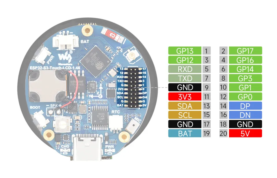
- I2C Interfaces
Pin Marking Function Description GND GND Power ground 3V3 3V3 3.3V output SCL SCL (GPIO10) I2C clock line, cannot be used as a regular GPIO SDA SDA (GPIO11) I2C data line, cannot be used as a regular GPIO - UART Interfaces
Pin Marking Function Description GND GND Power ground 3V3 3V3 3.3V output TXD TXD (GPIO43) UART data transmit or can be used as a regular GPIO RXD RXD (GPIO44) UART data receive or can be used as a regular GPIO - USB Interfaces
Pin Marking Function Description 5V 5V 5V output GND GND Power ground DN DN (GPIO19) Used for USB communication or as a regular GPIO. If used as a regular GPIO, you must enter download mode before each program flash DP DP (GPIO20) Used for USB communication or as a regular GPIO. If used as a regular GPIO, you must enter download mode before each program flash
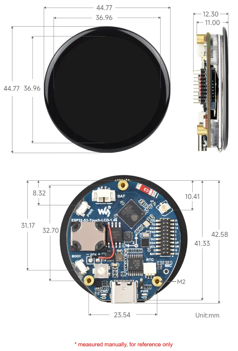
Dimensions
- Version without cover glass
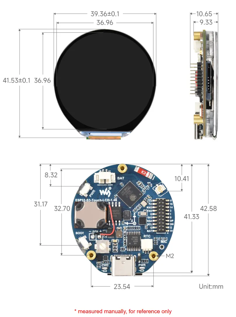
- Version with protective cover glass
Internal Hardware Connections
- LCD
LCD Pin ESP32-S3 LCD_SDA0 GPIO46 LCD_SDA1 GPIO45 LCD_SDA2 GPIO42 LCD_SDA3 GPIO41 LCD_SCK GPIO40 LCD_CS GPIO21 LCD_TE GPIO18 LCD_RST EXIO2 LCD_BL GPIO5 TP_SDA GPIO11 TP_SCL GPIO10 TP_INT GPIO4 TP_RST EXIO1 - TF Card
TF Card ESP32S3 SD_D0 / MISO GPIO16 SD_CMD / MOSI GPIO17 SD_SCK / SCLK GPIO14 SD_D3 / CS EXIO3 SD_D1 NC SD_D2 NC - QMI
QMI8658 ESP32S3 IMU_SCL GPIO10 IMU_SDA GPIO11 IMU_INT1 EXIO5 IMU_INT2 EXIO4 - RTC
PCF85063ATL ESP32S3 RTC_SCL GPIO10 RTC_SDA GPIO11 RTC_INT GPIO9 - MIC
Buzzer ESP32S3 MIC_WS GPIO2 MIC_SCK GPIO15 MIC_SD GPIO39 - SPEAKER
PCM5101 ESP32S3 Speak_DIN GPIO47 Speak_LRCK GPIO38 Speak_BCK GPIO48
Development Methods
The ESP32-S3-Touch-LCD-1.46 supports two development frameworks: Arduino IDE and ESP-IDF, providing flexibility for developers to choose the tool that best fits their project requirements and personal preference.
Both development methods have their own advantages. Developers can choose based on their needs and skill levels. Arduino is simple to learn and quick to start, suitable for beginners and non-professionals. ESP-IDF provides more advanced development tools and stronger control capabilities, suitable for developers with professional backgrounds or higher performance requirements, and is more appropriate for complex project development.
-
Arduino IDE is a convenient, flexible, and easy-to-use open-source electronics prototyping platform. It requires minimal foundational knowledge, allowing for rapid development after a short learning period. Arduino has a huge global user community, providing a vast amount of open-source code, project examples, and tutorials, as well as a rich library ecosystem that encapsulates complex functions, enabling developers to implement various features rapidly. You can refer to the Working with Arduino to complete the initial setup, and the tutorial also provides related example programs for reference.
-
ESP-IDF, short for Espressif IoT Development Framework, is a professional development framework launched by Espressif Systems for its ESP series of chips. It is based on C language development and includes compilers, debuggers, flashing tools, etc. It supports development via command line or integrated development environments (such as Visual Studio Code with the Espressif IDF plugin), which provides features like code navigation, project management, and debugging. We recommend using VS Code for development. For the specific configuration process, please refer to the Working with ESP-IDF. The tutorial also provides relevant example programs for reference.