ESP-IDF
This chapter contains the following sections. Please read as needed:
ESP-IDF Getting Started
New to ESP32 ESP-IDF development and looking to get started quickly? We have prepared a general Getting Started Tutorial for you.
- Section 1: Environment Setup
- Section 2: Running Examples
- Section 3: Creating a Project
- Section 4: Using Components
- Section 5: Debugging
- Section 6: FreeRTOS
- Section 7: Peripherals
- Section 8: Wi-Fi Programming
- Section 9: BLE Programming
Please Note: This tutorial uses the ESP32-S3-Zero as a teaching example, and all hardware code is based on its pinout. Before you start, it is recommended that you check the pinout of your development board to ensure the pin configuration is correct.
Setting Up Development Environment
For the ESP32-S3-Touch-LCD-1.54 development board, ESP-IDF V5.5.0 or above is required.
The following guide uses Windows as an example, demonstrating development using VS Code + the ESP-IDF extension. macOS and Linux users should refer to the official documentation.
The screenshots in this section use ESP-IDF V5.5.2 as an example. When installing, please select the ESP-IDF version that matches your board's example.
Install the ESP-IDF Development Environment
-
Download the installation manager from the ESP-IDF Installation Manager page. This is Espressif's latest cross-platform installer. The following steps demonstrate how to use its offline installation feature.
Click the Offline Installer tab on the page, then select Windows as the operating system and the ESP-IDF version you need (the version shown in the screenshot is for reference only — choose the version that fits your actual needs).

After confirming your selection, click the download button. The browser will automatically download two files: the ESP-IDF Offline Package (.zst) and the ESP-IDF Installer (.exe).

Please wait for both files to finish downloading.
-
Once the download is complete, double-click to run the ESP-IDF Installer (eim-gui-windows-x64.exe).
The installer will automatically detect if the offline package exists in the same directory. Click Install from archive.

Next, select the installation path. We recommend using the default path. If you need to customize it, ensure the path does not contain Chinese characters or spaces. Click Start installation to proceed.

-
When you see the following screen, the ESP-IDF installation is successful.

-
We recommend installing the drivers as well. Click Finish installation, then select Install driver.

Install Visual Studio Code and the ESP-IDF Extension
-
Download and install Visual Studio Code.
-
During installation, it is recommended to check Add "Open with Code" action to Windows Explorer file context menu to facilitate opening project folders quickly.
-
In VS Code, click the Extensions icon
 in the Activity Bar on the side (or use the shortcut Ctrl + Shift + X) to open the Extensions view.
 -
Enter ESP-IDF in the search box, locate the ESP-IDF extension, and click Install.

-
For ESP-IDF extension versions ≥ 2.0, the extension will automatically detect and recognize the ESP-IDF environment installed in the previous steps, requiring no manual configuration.
Example
The ESP-IDF examples are located in the ESP-IDF directory of the example package.
01_factory
This demo is a comprehensive demo of ESP32-Touch-LCD-1.54, which is also the default demo flashed at factory
Hardware Connection
- Connect the development board to the computer
Operation Result
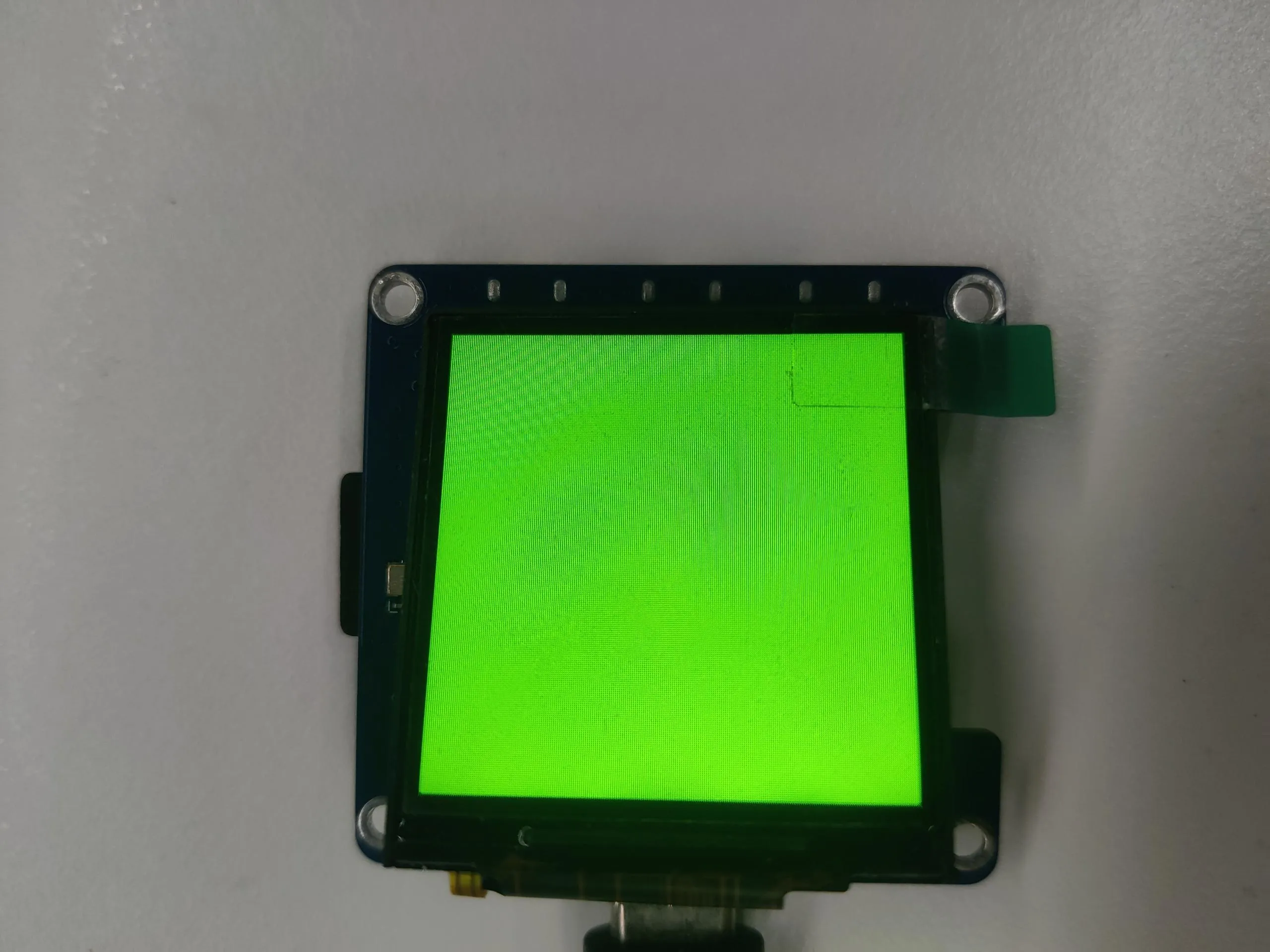 | 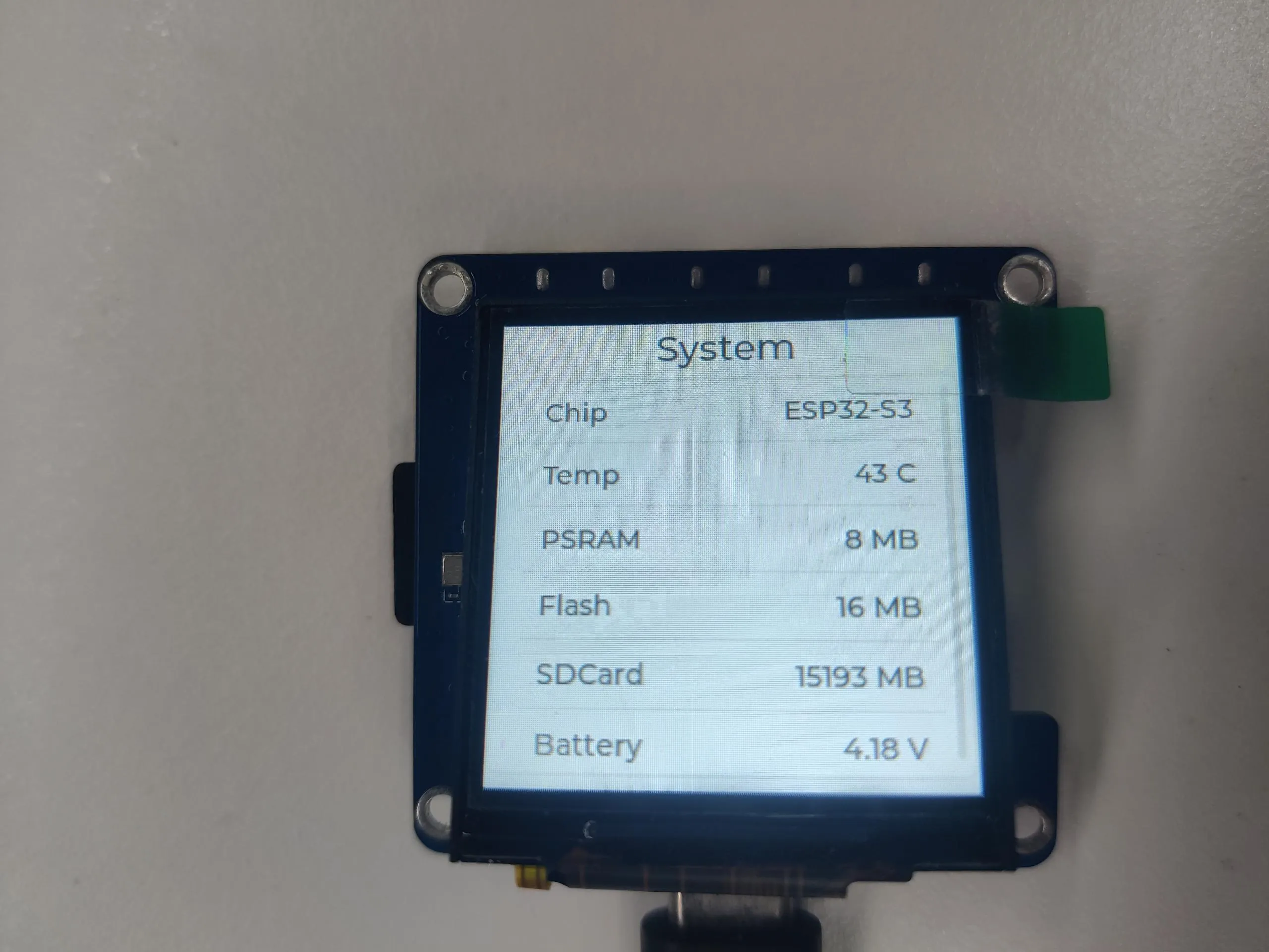 | 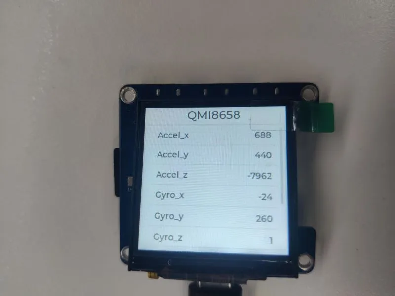 | 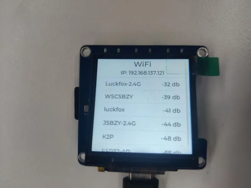 |
|---|
- The first page cycles through the colors red, green, and blue
- The second page displays development board information
- The third page shows the data read from the IMU
- The fourth page shows the IP address of the connected Wi-Fi (if not connected or connection fails, it displays 0.0.0.0) and the discovered Wi-Fi networks
Specific Operations
- Press and hold the left button, the speaker will play the sound captured by the microphone in real time
- Double-click the middle button to turn off the screen; double-click again to restore the display
- When powered by battery, long press the middle button to power on; long press again and release to power off
- Click the left or right button to switch pages
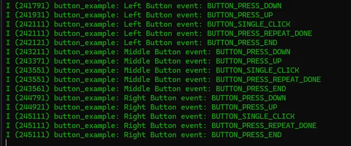
02_button_example
This example demonstrates how to use the espressif/button library to read button states such as single click, double click, and long press, and print them via serial port.
Hardware Connection
- Connect the development board to the computer
Code Analysis
-
Bind callback functions:
ret = iot_button_register_cb(boot_btn, BUTTON_PRESS_DOWN, NULL, button_event_cb, NULL);ret |= iot_button_register_cb(boot_btn, BUTTON_PRESS_UP, NULL, button_event_cb, NULL);ret |= iot_button_register_cb(boot_btn, BUTTON_PRESS_REPEAT, NULL, button_event_cb, NULL);ret |= iot_button_register_cb(boot_btn, BUTTON_PRESS_REPEAT_DONE, NULL, button_event_cb, NULL);ret |= iot_button_register_cb(boot_btn, BUTTON_SINGLE_CLICK, NULL, button_event_cb, NULL);ret |= iot_button_register_cb(boot_btn, BUTTON_DOUBLE_CLICK, NULL, button_event_cb, NULL);ret |= iot_button_register_cb(boot_btn, BUTTON_LONG_PRESS_START, NULL, button_event_cb, NULL);ret |= iot_button_register_cb(boot_btn, BUTTON_LONG_PRESS_HOLD, NULL, button_event_cb, NULL);ret |= iot_button_register_cb(boot_btn, BUTTON_LONG_PRESS_UP, NULL, button_event_cb, NULL);ret |= iot_button_register_cb(boot_btn, BUTTON_PRESS_END, NULL, button_event_cb, NULL);
Operation Result
- The screen shows no output
- Open the serial debugging tool; button information is printed to the serial port
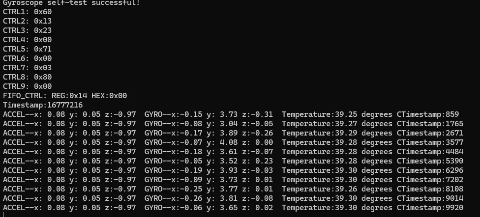
03_qmi8658_example
This demo demonstrates how to use the sensorlib library to read data from the qmi8658 and print it.
Hardware Connection
- Connect the development board to the computer
Code Analysis
-
Read Accelerometer, Gyroscope, and Timestamp data from the qmi8658
if (qmi.getDataReady()){if (qmi.getAccelerometer(acc.x, acc.y, acc.z)){printf("ACCEL--x:%5.2f y:%5.2f z:%5.2f ", acc.x, acc.y, acc.z);}if (qmi.getGyroscope(gyr.x, gyr.y, gyr.z)){printf("GYRO--x:%5.2f y:%5.2f z:%5.2f ", gyr.x, gyr.y, gyr.z);}printf("Temperature:%5.2f degrees C", qmi.getTemperature_C());}printf("Timestamp:%ld \r\n", qmi.getTimestamp());
Operation Result
- The screen shows no output
- Open the serial debugging tool; qmi8658 data information is printed to the serial port
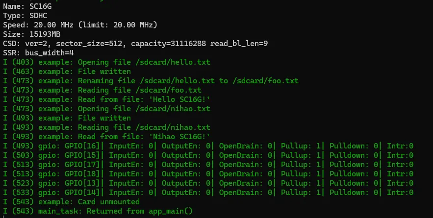
04_sd_card_test
This demo uses the ESP32-S3-Touch-LCD-1.54 to test the TF card read/write functionality.
Hardware Connection
- Insert the TF card into the card slot (TF card needs to be formatted as FAT32)
- Connect the development board to the computer
Code Analysis
-
Initialize and mount the TF card:
sdmmc_slot_config_t slot_config = SDMMC_SLOT_CONFIG_DEFAULT();#if EXAMPLE_IS_UHS1slot_config.flags |= SDMMC_SLOT_FLAG_UHS1;#endif// Set bus width to use:#ifdef CONFIG_EXAMPLE_SDMMC_BUS_WIDTH_4slot_config.width = 4;#elseslot_config.width = 1;#endif// On chips where the GPIOs used for the TF card can be configured, set them in// the slot_config structure:#ifdef CONFIG_SOC_SDMMC_USE_GPIO_MATRIXslot_config.clk = CONFIG_EXAMPLE_PIN_CLK;slot_config.cmd = CONFIG_EXAMPLE_PIN_CMD;slot_config.d0 = CONFIG_EXAMPLE_PIN_D0;#ifdef CONFIG_EXAMPLE_SDMMC_BUS_WIDTH_4slot_config.d1 = CONFIG_EXAMPLE_PIN_D1;slot_config.d2 = CONFIG_EXAMPLE_PIN_D2;slot_config.d3 = CONFIG_EXAMPLE_PIN_D3;#endif // CONFIG_EXAMPLE_SDMMC_BUS_WIDTH_4#endif // CONFIG_SOC_SDMMC_USE_GPIO_MATRIX// Enable internal pullups on enabled pins. The internal pullups// are insufficient however, please make sure 10k external pullups are// connected on the bus. This is for debug / example purpose only.slot_config.flags |= SDMMC_SLOT_FLAG_INTERNAL_PULLUP;ESP_LOGI(TAG, "Mounting filesystem");ret = esp_vfs_fat_sdmmc_mount(mount_point, &host, &slot_config, &mount_config, &card);
Operation Result
- The screen shows no output
- Open the serial debugging tool; TF card information is printed to the serial port
05_lvgl_example
This demo demonstrates running an lvgl example program on the ESP32-S3-Touch-LCD-1.54 (supports lvgl v8 and lvgl v9).
- The default LVGL version used is v9.3.0. To change the version, modify the LVGL configuration in the
main/idf_component.ymlfile, for example, change it tolvgl/lvgl:^8.4.0.
Hardware Connection
- Connect the development board to the computer
Code Analysis
-
Initialize:
/* LCD HW initialization */ESP_ERROR_CHECK(app_lcd_init());/* Touch initialization */app_touch_init();/* LVGL initialization */ESP_ERROR_CHECK(app_lvgl_init());
Operation Result
