Working with Arduino
This chapter contains the following sections. Please read as needed:
Arduino Getting Started
New to Arduino ESP32 development and looking for a quick start? We have prepared a comprehensive Getting Started Tutorial for you.
- Section 0: Getting to Know ESP32
- Section 1: Installing and Configuring Arduino IDE
- Section 2: Arduino Basics
- Section 3: Digital Output/Input
- Section 4: Analog Input
- Section 5: Pulse Width Modulation (PWM)
- Section 6: Serial Communication (UART)
- Section 7: I2C Communication
- Section 8: SPI Communication
- Section 9: Wi-Fi Basics
- Section 10: Web Server
- Section 11: Bluetooth
- Section 12: LVGL GUI Development
- Section 13: Comprehensive Project
Note: This tutorial uses the ESP32-S3-Zero as a reference example, and all hardware code is based on its pinout. Before you start, we recommend checking the pinout of your development board to ensure the pin configuration is correct.
Setting Up Development Environment
1. Installing and Configuring Arduino IDE
Please refer to the tutorial Installing and Configuring Arduino IDE to download and install the Arduino IDE and add ESP32 support.
| Board Name | Board Installation Requirement | Version Requirement |
|---|---|---|
| esp32 by Espressif Systems | "Install Offline" / "Install Online" | 3.0.5 |
2. Installing Libraries
To run the example, you need to install the corresponding library. The example code uses the GFX Library for Arduino library to drive the ST7789V2 display
and the Arduino_DriveBus library to drive the CST816T touch controller.
You can click this link to download the example package for the ESP32-S3-Touch-LCD-1.69 development board. The Arduino\libraries directory within this package contains all the necessary library files required for this tutorial.
| Library/File Name | Description | Version | Installation Method |
|---|---|---|---|
| Arduino_DriveBus | CST816, CST816 touch controller driver library | v1.0.1 | Install manually |
| GFX Library for Arduino | ST7789 display driver graphics library | v1.6.5 | Install via library manager or manually |
| SensorLib | PCF85063, QMI8658 sensor driver library | v0.4.1 | Install via library manager or manually |
| lvgl | LVGL graphics library | v8.4.0 | Install via library manager or manually |
| Mylibrary/pin_config.h | Board pin definitions and compatible board macros | - | Install manually |
| lv_conf.h | LVGL configuration file, with the performance monitor centered | - | Install manually |
There are strong dependencies between versions of LVGL and its driver libraries. For example, a driver written for LVGL v8 may not be compatible with LVGL v9. To ensure that the examples can be reproduced reliably, it is recommended to use the specific versions listed in the table above. Mixing different versions of libraries may lead to compilation failures or runtime errors.
Installation Steps:
-
Unzip the downloaded example package.
-
Copy all folders (Arduino_DriveBus, GFX_Library_for_Arduino, etc.) in the
Arduino\librariesdirectory to the Arduino library folder.infoThe path to the Arduino libraries folder is typically:
c:\Users\<username>\Documents\Arduino\libraries.You can also locate it in the Arduino IDE by going to File > Preferences and checking the "Sketchbook location". The libraries folder is the
librariessubfolder within this path. -
For other installation methods, please refer to: Arduino Library Management Tutorial.
3. Other Tips
-
The ESP32-S3-Touch-LCD-1.69 can be directly selected in the Arduino IDE.
-
The ESP32-S3-Touch-LCD-1.69 uses the ESP32-S3 native USB interface, not UART-to-USB. For serial communication:
-
The
printf()function can be used directly; -
To use the
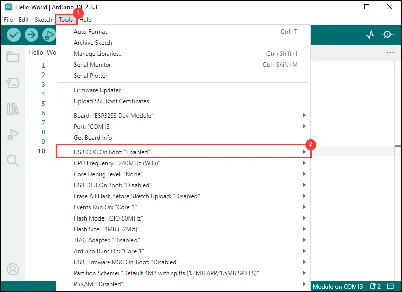
Serial.println()function, additional configuration is required: Enable the "USB CDC On Boot" option in the IDE's Tools menu, or declare anHWCDCobject in your code to handle USB serial communication.noteAs shown in the figure, set "USB CDC On Boot" in the "Tools" option of the Arduino IDE
-
Example
The Arduino examples are located in the Arduino/examples directory of the example package.
| Example | Basic Description | Dependency Library |
|---|---|---|
| 01_HelloWorld | Demonstrates basic graphics library functions, can also be used to test the basic performance of the display and random text display effects | GFX_Library_for_Arduino |
| 02_Drawing_board | Reads CST816T touch coordinates and draws continuous touch strokes on the screen | GFX_Library_for_Arduino, Arduino DriveBus |
| 03_GFX_AsciiTable | Prints ASCII characters in rows and columns on the screen according to the screen size | GFX_Library_for_Arduino |
| 04_GFX_ESPWiFiAnalyzer | Draws Wi-Fi band signal strength on the ST7789 display | GFX_Library_for_Arduino |
| 05_GFX_Clock | A simple ST7789 clock example implementing a clock with simple tick marks and time management | GFX_Library_for_Arduino |
| 06_GFX_PCF85063_simpleTime | Displays the current date and time centered | SensorLib, GFX_Library_for_Arduino |
| 07_LVGL_Measuring_voltage | Measures voltage using a voltage divider on a reserved pin, reads analog value from GPIO1 and calculates battery voltage using the divider formula | LVGL |
| 08_LVGL_PCF85063_simpleTime | Displays current time on the ST7789 display using the PCF85063 RTC module under LVGL | LVGL, SensorLib |
| 09_LVGL_Keys_Bee | Multi-function button usage | LVGL |
| 10_LVGL_QMI8658_ui | Uses LVGL charts to display real-time QMI8658 accelerometer and gyroscope three-axis data | LVGL, SensorLib |
| 11_LVGL_Arduino | LVGL example | LVGL, Arduino DriveBus |
01_HelloWorld
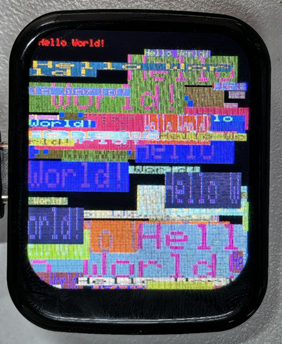
This example shows how to use the ST7789 display with the Arduino GFX library and the Arduino DriveBus library to implement dynamic text display. Specifically, it displays the text "Hello World!" at a fixed position on the display, then in a loop it displays the same text at random positions, colors, and sizes every second. This code can also be used to test the basic performance of the display.
Code
01_HelloWorld.ino
#include <Arduino.h>
#include "Arduino_GFX_Library.h"
#include "pin_config.h"
#include <Wire.h>
#include "HWCDC.h"

HWCDC USBSerial;

Arduino_DataBus *bus = new Arduino_ESP32SPI(LCD_DC, LCD_CS, LCD_SCK, LCD_MOSI);

Arduino_GFX *gfx = new Arduino_ST7789(bus, LCD_RST /* RST */,
                                      0 /* rotation */, true /* IPS */, LCD_WIDTH, LCD_HEIGHT, 0, 20, 0, 0);

void setup(void) {
  USBSerial.begin(115200);
  // USBSerial.setDebugOutput(true);
  // while(!USBSerial);
  USBSerial.println("Arduino_GFX Hello World example");

  // Init Display
  if (!gfx->begin()) {
    USBSerial.println("gfx->begin() failed!");
  }
  gfx->fillScreen(RGB565_BLACK);

  pinMode(LCD_BL, OUTPUT);
  digitalWrite(LCD_BL, HIGH);

  gfx->setCursor(10, 10);
  gfx->setTextColor(RGB565_RED);
  gfx->println("Hello World!");

  delay(5000);  // 5 seconds
}

void loop() {
  gfx->setCursor(random(gfx->width()), random(gfx->height()));
  gfx->setTextColor(random(0xffff), random(0xffff));
  gfx->setTextSize(random(6) /* x scale */, random(6) /* y scale */, random(2) /* pixel_margin */);
  gfx->println("Hello World!");

  delay(1000);  // 1 second
}
Code Analysis
-
Display initialization:
if (!gfx->begin()) {USBSerial.println("gfx->begin() failed!");} -
Clear the screen and display text:
gfx->fillScreen(RGB565_BLACK);gfx->setCursor(10, 10);gfx->setTextColor(RGB565_RED);gfx->println("Hello World!"); -
Animated display:
gfx->setCursor(random(gfx->width()), random(gfx->height()));gfx->setTextColor(random(0xffff), random(0xffff));gfx->setTextSize(random(6), random(6), random(2));gfx->println("Hello World!");
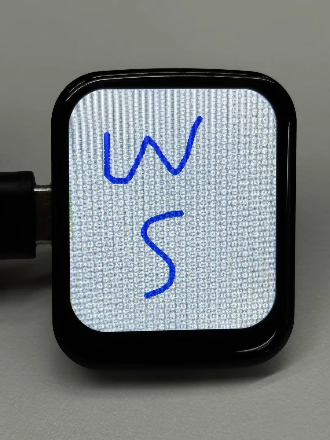
02_Drawing_board
This example demonstrates how to use the CST816T touch controller and the Arduino GFX library to implement touch drawing on an ESP32 development board. The code separates touch and display initialization into dedicated functions, reads touch interrupts and coordinates over 400 kHz I2C, and connects nearby touch points to make smoother continuous strokes. When the program starts, it also uses PWM to fade the backlight from dim to bright.
Code
02_Drawing_board.ino
#include <Wire.h>
#include <Arduino.h>
#include "pin_config.h"
#include "Arduino_GFX_Library.h"
#include "Arduino_DriveBus_Library.h"
#include "HWCDC.h"
HWCDC USBSerial;
Arduino_DataBus *bus = new Arduino_ESP32SPI(LCD_DC, LCD_CS, LCD_SCK, LCD_MOSI);
Arduino_GFX *gfx = new Arduino_ST7789(bus, LCD_RST /* RST */,
0 /* rotation */, true /* IPS */, LCD_WIDTH, LCD_HEIGHT, 0, 20, 0, 0);
static constexpr uint16_t DRAW_COLOR = RGB565_BLUE;
static constexpr uint16_t BACKGROUND_COLOR = RGB565_WHITE;
static constexpr int16_t DRAW_RADIUS = 3;
static constexpr int16_t LOADING_TEXT_X = 20;
static constexpr int16_t LOADING_TEXT_Y = 100;
static constexpr uint32_t TOUCH_STROKE_TIMEOUT_MS = 150;
static constexpr uint32_t TOUCH_LOG_INTERVAL_MS = 100;
static constexpr uint32_t TOUCH_I2C_SPEED = 400000;
std::shared_ptr<Arduino_IIC_DriveBus> IIC_Bus =
std::make_shared<Arduino_HWIIC>(IIC_SDA, IIC_SCL, &Wire);
void Arduino_IIC_Touch_Interrupt(void);
std::unique_ptr<Arduino_IIC> CST816T(new Arduino_CST816x(IIC_Bus, CST816T_DEVICE_ADDRESS,
TP_RST, TP_INT, Arduino_IIC_Touch_Interrupt));
struct TouchState {
int16_t lastX = -1;
int16_t lastY = -1;
uint32_t lastTouchMs = 0;
uint32_t lastLogMs = 0;
};
TouchState touchState;
void Arduino_IIC_Touch_Interrupt(void) {
CST816T->IIC_Interrupt_Flag = true;
}
void initializeTouch() {
while (CST816T->begin(TOUCH_I2C_SPEED) == false) {
USBSerial.println("CST816T initialization fail");
delay(2000);
}
USBSerial.println("CST816T initialization successfully");
CST816T->IIC_Write_Device_State(CST816T->Arduino_IIC_Touch::Device::TOUCH_DEVICE_INTERRUPT_MODE,
CST816T->Arduino_IIC_Touch::Device_Mode::TOUCH_DEVICE_INTERRUPT_PERIODIC);
CST816T->IIC_Interrupt_Flag = false;
}
void showLoadingScreen() {
gfx->fillScreen(BACKGROUND_COLOR);
gfx->setCursor(LOADING_TEXT_X, LOADING_TEXT_Y);
gfx->setTextColor(DRAW_COLOR);
gfx->setTextSize(2);
for (int brightness = 0; brightness <= 255; brightness++) {
analogWrite(LCD_BL, brightness);
gfx->println("Loading board");
delay(3);
gfx->setCursor(LOADING_TEXT_X, LOADING_TEXT_Y);
}
delay(500);
gfx->fillScreen(BACKGROUND_COLOR);
}
void initializeDisplay() {
gfx->begin();
pinMode(LCD_BL, OUTPUT);
digitalWrite(LCD_BL, HIGH);
showLoadingScreen();
}
bool readTouchPoint(int16_t &touchX, int16_t &touchY) {
if (CST816T->IIC_Interrupt_Flag != true) {
return false;
}
CST816T->IIC_Interrupt_Flag = false;
int32_t fingers = CST816T->IIC_Read_Device_Value(CST816T->Arduino_IIC_Touch::Value_Information::TOUCH_FINGER_NUMBER);
if (fingers <= 0) {
touchState.lastX = -1;
touchState.lastY = -1;
return false;
}
int32_t rawX = CST816T->IIC_Read_Device_Value(CST816T->Arduino_IIC_Touch::Value_Information::TOUCH_COORDINATE_X);
int32_t rawY = CST816T->IIC_Read_Device_Value(CST816T->Arduino_IIC_Touch::Value_Information::TOUCH_COORDINATE_Y);
if (rawX < 0 || rawY < 0) {
return false;
}
touchX = constrain((int16_t)rawX, 0, LCD_WIDTH - 1);
touchY = constrain((int16_t)rawY, 0, LCD_HEIGHT - 1);
return true;
}
void drawTouchPoint(int16_t touchX, int16_t touchY) {
uint32_t now = millis();
// When two touch points are close in time, connect them so the stroke feels continuous.
if (touchState.lastX >= 0 && touchState.lastY >= 0 &&
(now - touchState.lastTouchMs) <= TOUCH_STROKE_TIMEOUT_MS) {
gfx->drawLine(touchState.lastX, touchState.lastY, touchX, touchY, DRAW_COLOR);
}
gfx->fillCircle(touchX, touchY, DRAW_RADIUS, DRAW_COLOR);
touchState.lastX = touchX;
touchState.lastY = touchY;
touchState.lastTouchMs = now;
if ((now - touchState.lastLogMs) >= TOUCH_LOG_INTERVAL_MS) {
USBSerial.printf("Touch X:%d Y:%d\n", touchX, touchY);
touchState.lastLogMs = now;
}
}
void setup() {
USBSerial.begin(115200);
initializeTouch();
initializeDisplay();
}
void loop() {
int16_t touchX = 0;
int16_t touchY = 0;
if (!readTouchPoint(touchX, touchY)) {
return;
}
drawTouchPoint(touchX, touchY);
}
Code Analysis
-
Touch and display initialization:
initializeTouch();initializeDisplay(); -
Touch drawing:
readTouchPoint()reads coordinates only after a touch interrupt is triggered and usesconstrain()to keep the coordinates inside the screen area.drawTouchPoint()draws lines between touch points that occur within 150 ms of each other, then fills the stroke with small circles.
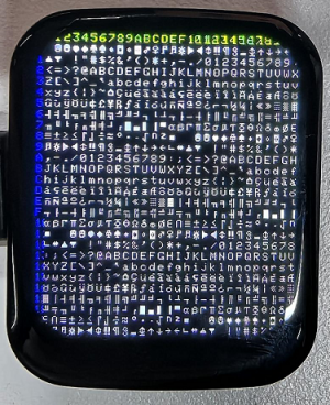
03_GFX_AsciiTable
This example shows how to create an ASCII table display effect using the ST7789 display and the Arduino GFX library. Specifically, after initializing the display, the code displays ASCII character indices on the screen according to predefined colors and positions. First, the string "Arduino_GFX AsciiTable example" is printed to the serial monitor via USBSerial. Then indices are displayed in two colors (green and blue) at fixed positions, followed by the full ASCII character table displayed in white on a black background.
Code
03_GFX_AsciiTable.ino
#include <Arduino.h>
#include "Arduino_GFX_Library.h"
#include "pin_config.h"
#include <Wire.h>
#include "HWCDC.h"
HWCDC USBSerial;
Arduino_DataBus *bus = new Arduino_ESP32SPI(LCD_DC, LCD_CS, LCD_SCK, LCD_MOSI);
Arduino_GFX *gfx = new Arduino_ST7789(bus, LCD_RST /* RST */,
0 /* rotation */, true /* IPS */, LCD_WIDTH, LCD_HEIGHT, 0, 20, 0, 0);
static constexpr uint16_t BACKGROUND_COLOR = RGB565_BLACK;
static constexpr uint16_t HEADER_TEXT_COLOR = RGB565_GREEN;
static constexpr uint16_t INDEX_TEXT_COLOR = RGB565_BLUE;
static constexpr uint16_t ASCII_TEXT_COLOR = RGB565_WHITE;
void setup(void) {
USBSerial.begin(115200);
// USBSerial.setDebugOutput(true);
// while(!USBSerial);
USBSerial.println("Arduino_GFX AsciiTable example");
int columnCount = LCD_WIDTH / 8;
int rowCount = LCD_HEIGHT / 10;
#ifdef GFX_EXTRA_PRE_INIT
GFX_EXTRA_PRE_INIT();
#endif
// Init Display
if (!gfx->begin()) {
   USBSerial.println("gfx->begin() failed!");
 }
gfx->fillScreen(BACKGROUND_COLOR);
pinMode(LCD_BL, OUTPUT);
digitalWrite(LCD_BL, HIGH);
gfx->setTextColor(HEADER_TEXT_COLOR);
for (int x = 0; x < columnCount; x++) {
gfx->setCursor(10 + x * 8, 2);
gfx->print(x, 16);
}
gfx->setTextColor(INDEX_TEXT_COLOR);
for (int y = 0; y < rowCount; y++) {
gfx->setCursor(2, 12 + y * 10);
gfx->print(y, 16);
}
char c = 0;
for (int y = 0; y < rowCount; y++) {
for (int x = 0; x < columnCount; x++) {
gfx->drawChar(10 + x * 8, 12 + y * 10, c++, ASCII_TEXT_COLOR, BACKGROUND_COLOR);
}
}
delay(5000); // 5 seconds
}
void loop() {
}
Code Analysis
-
Initialize the display:
if (!gfx->begin()) {USBSerial.println("gfx->begin() failed!");} -
Calculate rows and columns and label them:
Based on the display dimensions, it calculates the number of columns and rows that can be displayed. Then, using two loops with different text colors, it prints row and column numbers on the display, making it easy to determine character positions when drawing the ASCII table later.
int columnCount = LCD_WIDTH / 8;int rowCount = LCD_HEIGHT / 10;// Label the column numbergfx->setTextColor(HEADER_TEXT_COLOR);for (int x = 0; x < columnCount; x++) {gfx->setCursor(10 + x * 8, 2);gfx->print(x, 16);}// Label the row numbergfx->setTextColor(INDEX_TEXT_COLOR);for (int y = 0; y < rowCount; y++) {gfx->setCursor(2, 12 + y * 10);gfx->print(y, 16);} -
Draws the ASCII character table:
char c = 0;for (int y = 0; y < rowCount; y++) {for (int x = 0; x < columnCount; x++) {gfx->drawChar(10 + x * 8, 12 + y * 10, c++, ASCII_TEXT_COLOR, BACKGROUND_COLOR);}}
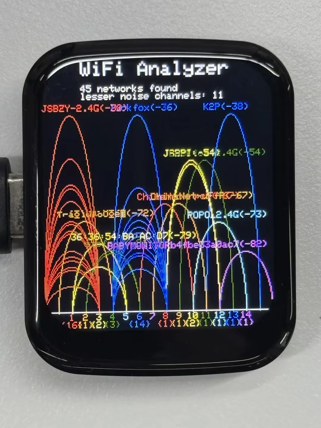
04_GFX_ESPWiFiAnalyzer
This example demonstrates drawing Wi-Fi band signal strength on the ST7789 display, implementing the functionality of a Wi-Fi analyzer.
Code
04_GFX_ESPWiFiAnalyzer.ino
#include <Arduino.h>
#include "Arduino_GFX_Library.h"
#include "pin_config.h"
#include <Wire.h>
#include "HWCDC.h"
Arduino_DataBus *bus = new Arduino_ESP32SPI(LCD_DC, LCD_CS, LCD_SCK, LCD_MOSI);
Arduino_GFX *gfx = new Arduino_ST7789(bus, LCD_RST /* RST */,
0 /* rotation */, true /* IPS */, LCD_WIDTH, LCD_HEIGHT, 0, 20, 0, 0);
#if defined(ESP32)
#include "WiFi.h"
#else
#include "ESP8266WiFi.h"
#define log_i(format, ...) Serial.printf(format, ##__VA_ARGS__)
#endif
int16_t w, h, text_size, banner_height, graph_baseline, graph_height, channel_width, signal_width;
// RSSI RANGE
#define RSSI_CEILING -40
#define RSSI_FLOOR -100
// Channel color mapping from channel 1 to 14
uint16_t channel_color[] = {
RGB565_RED, RGB565_ORANGE, RGB565_YELLOW, RGB565_GREEN, RGB565_CYAN, RGB565_BLUE, RGB565_MAGENTA,
RGB565_RED, RGB565_ORANGE, RGB565_YELLOW, RGB565_GREEN, RGB565_CYAN, RGB565_BLUE, RGB565_MAGENTA
};
uint8_t scan_count = 0;
bool has_scan_result = false;
static constexpr int16_t BANNER_TEXT_X = 40;
void drawScanningStatus() {
gfx->fillRect(0, banner_height, w, h - banner_height, RGB565_BLACK);
gfx->setTextSize(1);
gfx->setTextColor(RGB565_WHITE);
gfx->setCursor(BANNER_TEXT_X, banner_height);
gfx->print("Scanning WiFi...");
gfx->setTextColor(RGB565_LIGHTGREY);
gfx->setCursor(BANNER_TEXT_X, banner_height + 10);
gfx->print("Please wait");
// Draw the channel axis immediately so the screen looks alive while the
// synchronous WiFi scan is running.
gfx->drawFastHLine(0, graph_baseline, gfx->width(), RGB565_DARKGREY);
for (int32_t channel = 1; channel <= 14; channel++) {
int16_t idx = channel - 1;
int16_t offset = (channel + 1) * channel_width;
gfx->setTextColor(channel_color[idx]);
gfx->setCursor(offset - ((channel < 10) ? 3 : 6), graph_baseline + 2);
gfx->print(channel);
}
}
void setup() {
Serial.begin(115200);
// Serial.setDebugOutput(true);
// while(!Serial);
Serial.println("Arduino_GFX ESP WiFi Analyzer example");
// Set WiFi to station mode and disconnect from an AP if it was previously connected
WiFi.mode(WIFI_STA);
WiFi.disconnect();
delay(100);
#ifdef GFX_EXTRA_PRE_INIT
GFX_EXTRA_PRE_INIT();
#endif
#if defined(LCD_PWR_PIN)
pinMode(LCD_PWR_PIN, OUTPUT); // sets the pin as output
digitalWrite(LCD_PWR_PIN, HIGH); // power on
#endif
// Init Display
if (!gfx->begin()) {
Serial.println("gfx->begin() failed!");
}
w = gfx->width();
h = gfx->height();
text_size = (h < 200) ? 1 : 2;
banner_height = text_size * 3 * 4;
graph_baseline = h - 20; // minus 2 text lines
graph_height = graph_baseline - banner_height - 30; // minus 3 text lines
channel_width = w / 17;
signal_width = channel_width * 2;
pinMode(LCD_BL, OUTPUT);
digitalWrite(LCD_BL, HIGH);
// init banner
gfx->setTextSize(text_size);
gfx->fillScreen(RGB565_BLACK);
gfx->setTextColor(RGB565_RED);
gfx->setCursor(BANNER_TEXT_X, 0);
// gfx->print("ESP");
gfx->setTextColor(RGB565_WHITE);
gfx->print("WiFi Analyzer");
}
bool matchBssidPrefix(uint8_t *a, uint8_t *b) {
for (uint8_t i = 0; i < 5; i++) { // only compare first 5 bytes
if (a[i] != b[i]) {
return false;
}
}
return true;
}
void loop() {
uint8_t ap_count_list[] = { 0, 0, 0, 0, 0, 0, 0, 0, 0, 0, 0, 0, 0, 0 };
int32_t noise_list[] = { RSSI_FLOOR, RSSI_FLOOR, RSSI_FLOOR, RSSI_FLOOR, RSSI_FLOOR, RSSI_FLOOR, RSSI_FLOOR, RSSI_FLOOR, RSSI_FLOOR, RSSI_FLOOR, RSSI_FLOOR, RSSI_FLOOR, RSSI_FLOOR, RSSI_FLOOR };
int32_t peak_list[] = { RSSI_FLOOR, RSSI_FLOOR, RSSI_FLOOR, RSSI_FLOOR, RSSI_FLOOR, RSSI_FLOOR, RSSI_FLOOR, RSSI_FLOOR, RSSI_FLOOR, RSSI_FLOOR, RSSI_FLOOR, RSSI_FLOOR, RSSI_FLOOR, RSSI_FLOOR };
int16_t peak_id_list[] = { -1, -1, -1, -1, -1, -1, -1, -1, -1, -1, -1, -1, -1, -1 };
int32_t channel;
int16_t idx;
int32_t rssi;
uint8_t *bssid;
String ssid;
uint16_t color;
int16_t height, offset, text_width;
if (!has_scan_result) {
drawScanningStatus();
}
// WiFi.scanNetworks will return the number of networks found
#if defined(ESP32)
int n = WiFi.scanNetworks(false /* async */, true /* show_hidden */, true /* passive */, 500 /* max_ms_per_chan */);
#else
int n = WiFi.scanNetworks(false /* async */, true /* show_hidden */);
#endif
// clear old graph
gfx->fillRect(0, banner_height, w, h - banner_height, RGB565_BLACK);
gfx->setTextSize(1);
if (n == 0) {
gfx->setTextColor(RGB565_WHITE);
gfx->setCursor(0, banner_height);
gfx->println("no networks found");
} else {
for (int i = 0; i < n; i++) {
channel = WiFi.channel(i);
idx = channel - 1;
rssi = WiFi.RSSI(i);
bssid = WiFi.BSSID(i);
// channel peak stat
if (peak_list[idx] < rssi) {
peak_list[idx] = rssi;
peak_id_list[idx] = i;
}
// check signal come from same AP
bool duplicate_SSID = false;
for (int j = 0; j < i; j++) {
if ((WiFi.channel(j) == channel) && matchBssidPrefix(WiFi.BSSID(j), bssid)) {
duplicate_SSID = true;
break;
}
}
if (!duplicate_SSID) {
ap_count_list[idx]++;
// noise stat
int32_t noise = rssi - RSSI_FLOOR;
noise *= noise;
if (channel > 4) {
noise_list[idx - 4] += noise;
}
if (channel > 3) {
noise_list[idx - 3] += noise;
}
if (channel > 2) {
noise_list[idx - 2] += noise;
}
if (channel > 1) {
noise_list[idx - 1] += noise;
}
noise_list[idx] += noise;
if (channel < 14) {
noise_list[idx + 1] += noise;
}
if (channel < 13) {
noise_list[idx + 2] += noise;
}
if (channel < 12) {
noise_list[idx + 3] += noise;
}
if (channel < 11) {
noise_list[idx + 4] += noise;
}
}
}
// plot found WiFi info
for (int i = 0; i < n; i++) {
channel = WiFi.channel(i);
idx = channel - 1;
rssi = WiFi.RSSI(i);
color = channel_color[idx];
height = constrain(map(rssi, RSSI_FLOOR, RSSI_CEILING, 1, graph_height), 1, graph_height);
offset = (channel + 1) * channel_width;
// trim rssi with RSSI_FLOOR
if (rssi < RSSI_FLOOR) {
rssi = RSSI_FLOOR;
}
// plot chart
// gfx->drawLine(offset, graph_baseline - height, offset - signal_width, graph_baseline + 1, color);
// gfx->drawLine(offset, graph_baseline - height, offset + signal_width, graph_baseline + 1, color);
gfx->startWrite();
gfx->writeEllipseHelper(offset, graph_baseline + 1, signal_width, height, 0b0011, color);
gfx->endWrite();
if (i == peak_id_list[idx]) {
// Print SSID, signal strengh and if not encrypted
String ssid = WiFi.SSID(i);
if (ssid.length() == 0) {
ssid = WiFi.BSSIDstr(i);
}
text_width = (ssid.length() + 6) * 6;
if (text_width > w) {
offset = 0;
} else {
offset -= signal_width;
if ((offset + text_width) > w) {
offset = w - text_width;
}
}
gfx->setTextColor(color);
gfx->setCursor(offset, graph_baseline - 10 - height);
gfx->print(ssid);
gfx->print('(');
gfx->print(rssi);
gfx->print(')');
#if defined(ESP32)
if (WiFi.encryptionType(i) == WIFI_AUTH_OPEN)
#else
if (WiFi.encryptionType(i) == ENC_TYPE_NONE)
#endif
{
gfx->print('*');
}
}
}
}
// print WiFi stat
gfx->setTextColor(RGB565_WHITE);
gfx->setCursor(BANNER_TEXT_X, banner_height);
gfx->print(n);
gfx->print(" networks found");
gfx->setCursor(BANNER_TEXT_X, banner_height + 8);
gfx->print("lesser noise channels: ");
bool listed_first_channel = false;
int32_t min_noise = noise_list[0]; // init with channel 1 value
for (channel = 2; channel <= 11; channel++) // channels 12-14 may not available
{
idx = channel - 1;
log_i("min_noise: %d, noise_list[%d]: %d", min_noise, idx, noise_list[idx]);
if (noise_list[idx] < min_noise) {
min_noise = noise_list[idx];
}
}
for (channel = 1; channel <= 11; channel++) // channels 12-14 may not available
{
idx = channel - 1;
// check channel with min noise
if (noise_list[idx] == min_noise) {
if (!listed_first_channel) {
listed_first_channel = true;
} else {
gfx->print(", ");
}
gfx->print(channel);
}
}
// draw graph base axle
gfx->drawFastHLine(0, graph_baseline, gfx->width(), RGB565_WHITE);
for (channel = 1; channel <= 14; channel++) {
idx = channel - 1;
offset = (channel + 1) * channel_width;
gfx->setTextColor(channel_color[idx]);
gfx->setCursor(offset - ((channel < 10) ? 3 : 6), graph_baseline + 2);
gfx->print(channel);
if (ap_count_list[idx] > 0) {
gfx->setCursor(offset - ((ap_count_list[idx] < 10) ? 9 : 12), graph_baseline + 8 + 2);
gfx->print('{');
gfx->print(ap_count_list[idx]);
gfx->print('}');
}
}
has_scan_result = true;
// Wait a bit before scanning again
// delay(SCAN_INTERVAL);
#if defined(SCAN_COUNT_SLEEP)
// POWER SAVING
if (++scan_count >= SCAN_COUNT_SLEEP) {
#if defined(LCD_PWR_PIN)
pinMode(LCD_PWR_PIN, INPUT); // disable pin
#endif
#if defined(GFX_BL)
pinMode(GFX_BL, INPUT); // disable pin
#endif
#if defined(ESP32)
esp_sleep_enable_ext0_wakeup(GPIO_NUM_36, LOW);
esp_deep_sleep_start();
#else
ESP.deepSleep(0);
#endif
}
#endif // defined(SCAN_COUNT_SLEEP)
}
Code Analysis
-
setup():Initializes serial communication; Sets Wi-Fi to station mode and disconnects; Initializes the display, gets screen dimensions and calculates various drawing parameters; Sets the screen background to black and draws the centered title bar.
-
loop():Calls
drawScanningStatus()before the first scan to show a scanning message and channel axis; Scans Wi-Fi networks and retrieves network information, including channel, RSSI, BSSID, and SSID; Counts the number of networks per channel, noise levels, and peak signal strengths; Clears the old graph and draws a new one based on the scan results, including signal strength ellipses and network information text; Prints the number of networks found and the channels with the least noise on two lines; Draws the graph baseline and channel numbers; Enters low-power mode based on conditions.
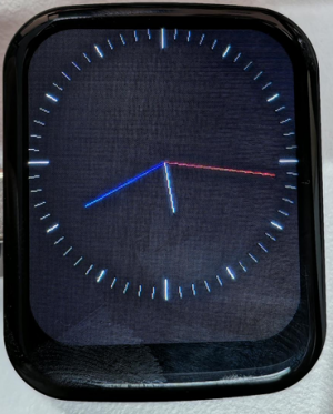
05_GFX_Clock
This example demonstrates a simple ST7789 clock example, implementing a clock with simple tick marks and time management.
Code
05_GFX_Clock.ino
#include <Arduino.h>
#include "Arduino_GFX_Library.h"
#include "pin_config.h"
#include <Wire.h>
#include "HWCDC.h"
HWCDC USBSerial;
// SensorPCF85063 rtc;
Arduino_DataBus *bus = new Arduino_ESP32SPI(LCD_DC, LCD_CS, LCD_SCK, LCD_MOSI);
Arduino_GFX *gfx = new Arduino_ST7789(bus, LCD_RST /* RST */,
0 /* rotation */, true /* IPS */, LCD_WIDTH, LCD_HEIGHT, 0, 20, 0, 0);
#define BACKGROUND RGB565_BLACK
#define MARK_COLOR RGB565_WHITE
#define SUBMARK_COLOR RGB565_DARKGREY // RGB565_LIGHTGREY
#define HOUR_COLOR RGB565_WHITE
#define MINUTE_COLOR RGB565_BLUE // RGB565_LIGHTGREY
#define SECOND_COLOR RGB565_RED
#define SIXTIETH 0.016666667
#define TWELFTH 0.08333333
#define SIXTIETH_RADIAN 0.10471976
#define TWELFTH_RADIAN 0.52359878
#define RIGHT_ANGLE_RADIAN 1.5707963
static uint8_t conv2d(const char *p)
{
uint8_t v = 0;
return (10 * (*p - '0')) + (*++p - '0');
}
static int16_t w, h, center;
static int16_t hHandLen, mHandLen, sHandLen, markLen;
static float sdeg, mdeg, hdeg;
static int16_t osx = 0, osy = 0, omx = 0, omy = 0, ohx = 0, ohy = 0; // Saved H, M, S x & y coords
static int16_t nsx, nsy, nmx, nmy, nhx, nhy; // H, M, S x & y coords
static int16_t xMin, yMin, xMax, yMax; // redraw range
static int16_t hh, mm, ss;
static unsigned long targetTime; // next action time
static int16_t *cached_points;
static uint16_t cached_points_idx = 0;
static int16_t *last_cached_point;
void setup(void)
{
USBSerial.begin(115200);
USBSerial.println("Arduino_GFX Clock example");
// Init Display
if (!gfx->begin()) {
   USBSerial.println("gfx->begin() failed!");
 }
gfx->fillScreen(BACKGROUND);
pinMode(LCD_BL, OUTPUT);
digitalWrite(LCD_BL, HIGH);
// init LCD constant
w = gfx->width();
h = gfx->height();
if (w < h)
{
center = w / 2;
}
else
{
center = h / 2;
}
hHandLen = center * 3 / 8;
mHandLen = center * 2 / 3;
sHandLen = center * 5 / 6;
markLen = sHandLen / 6;
cached_points = (int16_t *)malloc((hHandLen + 1 + mHandLen + 1 + sHandLen + 1) * 2 * 2);
// Draw 60 clock marks
draw_round_clock_mark(
// draw_square_clock_mark(
center - markLen, center,
center - (markLen * 2 / 3), center,
center - (markLen / 2), center);
hh = conv2d(__TIME__);
mm = conv2d(__TIME__ + 3);
ss = conv2d(__TIME__ + 6);
targetTime = ((millis() / 1000) + 1) * 1000;
}
void loop()
{
unsigned long cur_millis = millis();
if (cur_millis >= targetTime)
{
targetTime += 1000;
ss++; // Advance second
if (ss == 60)
{
ss = 0;
mm++; // Advance minute
if (mm > 59)
{
mm = 0;
hh++; // Advance hour
if (hh > 23)
{
hh = 0;
}
}
}
}
// Pre-compute hand degrees, x & y coords for a fast screen update
sdeg = SIXTIETH_RADIAN * ((0.001 * (cur_millis % 1000)) + ss); // 0-59 (includes millis)
nsx = cos(sdeg - RIGHT_ANGLE_RADIAN) * sHandLen + center;
nsy = sin(sdeg - RIGHT_ANGLE_RADIAN) * sHandLen + center;
if ((nsx != osx) || (nsy != osy))
{
mdeg = (SIXTIETH * sdeg) + (SIXTIETH_RADIAN * mm); // 0-59 (includes seconds)
hdeg = (TWELFTH * mdeg) + (TWELFTH_RADIAN * hh); // 0-11 (includes minutes)
mdeg -= RIGHT_ANGLE_RADIAN;
hdeg -= RIGHT_ANGLE_RADIAN;
nmx = cos(mdeg) * mHandLen + center;
nmy = sin(mdeg) * mHandLen + center;
nhx = cos(hdeg) * hHandLen + center;
nhy = sin(hdeg) * hHandLen + center;
// redraw hands
redraw_hands_cached_draw_and_erase();
ohx = nhx;
ohy = nhy;
omx = nmx;
omy = nmy;
osx = nsx;
osy = nsy;
delay(1);
}
}
void draw_round_clock_mark(int16_t innerR1, int16_t outerR1, int16_t innerR2, int16_t outerR2, int16_t innerR3, int16_t outerR3)
{
float x, y;
int16_t x0, x1, y0, y1, innerR, outerR;
uint16_t c;
for (uint8_t i = 0; i < 60; i++)
{
if ((i % 15) == 0)
{
innerR = innerR1;
outerR = outerR1;
c = MARK_COLOR;
}
else if ((i % 5) == 0)
{
innerR = innerR2;
outerR = outerR2;
c = MARK_COLOR;
}
else
{
innerR = innerR3;
outerR = outerR3;
c = SUBMARK_COLOR;
}
mdeg = (SIXTIETH_RADIAN * i) - RIGHT_ANGLE_RADIAN;
x = cos(mdeg);
y = sin(mdeg);
x0 = x * outerR + center;
y0 = y * outerR + center;
x1 = x * innerR + center;
y1 = y * innerR + center;
gfx->drawLine(x0, y0, x1, y1, c);
}
}
void draw_square_clock_mark(int16_t innerR1, int16_t outerR1, int16_t innerR2, int16_t outerR2, int16_t innerR3, int16_t outerR3)
{
float x, y;
int16_t x0, x1, y0, y1, innerR, outerR;
uint16_t c;
for (uint8_t i = 0; i < 60; i++)
{
if ((i % 15) == 0)
{
innerR = innerR1;
outerR = outerR1;
c = MARK_COLOR;
}
else if ((i % 5) == 0)
{
innerR = innerR2;
outerR = outerR2;
c = MARK_COLOR;
}
else
{
innerR = innerR3;
outerR = outerR3;
c = SUBMARK_COLOR;
}
if ((i >= 53) || (i < 8))
{
x = tan(SIXTIETH_RADIAN * i);
x0 = center + (x * outerR);
y0 = center + (1 - outerR);
x1 = center + (x * innerR);
y1 = center + (1 - innerR);
}
else if (i < 23)
{
y = tan((SIXTIETH_RADIAN * i) - RIGHT_ANGLE_RADIAN);
x0 = center + (outerR);
y0 = center + (y * outerR);
x1 = center + (innerR);
y1 = center + (y * innerR);
}
else if (i < 38)
{
x = tan(SIXTIETH_RADIAN * i);
x0 = center - (x * outerR);
y0 = center + (outerR);
x1 = center - (x * innerR);
y1 = center + (innerR);
}
else if (i < 53)
{
y = tan((SIXTIETH_RADIAN * i) - RIGHT_ANGLE_RADIAN);
x0 = center + (1 - outerR);
y0 = center - (y * outerR);
x1 = center + (1 - innerR);
y1 = center - (y * innerR);
}
gfx->drawLine(x0, y0, x1, y1, c);
}
}
void redraw_hands_cached_draw_and_erase() {
    gfx->startWrite();
    draw_and_erase_cached_line(center, center, nsx, nsy, SECOND_COLOR, cached_points, sHandLen + 1, false, false);
    draw_and_erase_cached_line(center, center, nhx, nhy, HOUR_COLOR, cached_points + ((sHandLen + 1) * 2), hHandLen + 1, true, false);
    draw_and_erase_cached_line(center, center, nmx, nmy, MINUTE_COLOR, cached_points + ((sHandLen + 1 + hHandLen + 1) * 2), mHandLen + 1, true, true);
    gfx->endWrite();
}
void draw_and_erase_cached_line(int16_t x0, int16_t y0, int16_t x1, int16_t y1, int16_t color, int16_t *cache, int16_t cache_len, bool cross_check_second, bool cross_check_hour)
{
#if defined(ESP8266)
yield();
#endif
bool steep = _diff(y1, y0) > _diff(x1, x0);
if (steep)
{
_swap_int16_t(x0, y0);
_swap_int16_t(x1, y1);
}
int16_t dx, dy;
dx = _diff(x1, x0);
dy = _diff(y1, y0);
int16_t err = dx / 2;
int8_t xstep = (x0 < x1) ? 1 : -1;
int8_t ystep = (y0 < y1) ? 1 : -1;
x1 += xstep;
int16_t x, y, ox, oy;
for (uint16_t i = 0; i <= dx; i++)
{
if (steep)
{
x = y0;
y = x0;
}
else
{
x = x0;
y = y0;
}
ox = *(cache + (i * 2));
oy = *(cache + (i * 2) + 1);
if ((x == ox) && (y == oy))
{
if (cross_check_second || cross_check_hour)
{
write_cache_pixel(x, y, color, cross_check_second, cross_check_hour);
}
}
else
{
write_cache_pixel(x, y, color, cross_check_second, cross_check_hour);
if ((ox > 0) || (oy > 0))
{
write_cache_pixel(ox, oy, BACKGROUND, cross_check_second, cross_check_hour);
}
*(cache + (i * 2)) = x;
*(cache + (i * 2) + 1) = y;
}
if (err < dy)
{
y0 += ystep;
err += dx;
}
err -= dy;
x0 += xstep;
}
for (uint16_t i = dx + 1; i < cache_len; i++)
{
ox = *(cache + (i * 2));
oy = *(cache + (i * 2) + 1);
if ((ox > 0) || (oy > 0))
{
write_cache_pixel(ox, oy, BACKGROUND, cross_check_second, cross_check_hour);
}
*(cache + (i * 2)) = 0;
*(cache + (i * 2) + 1) = 0;
}
}
void write_cache_pixel(int16_t x, int16_t y, int16_t color, bool cross_check_second, bool cross_check_hour)
{
int16_t *cache = cached_points;
if (cross_check_second)
{
for (uint16_t i = 0; i <= sHandLen; i++)
{
if ((x == *(cache++)) && (y == *(cache)))
{
return;
}
cache++;
}
}
if (cross_check_hour)
{
cache = cached_points + ((sHandLen + 1) * 2);
for (uint16_t i = 0; i <= hHandLen; i++)
{
if ((x == *(cache++)) && (y == *(cache)))
{
return;
}
cache++;
}
}
gfx->writePixel(x, y, color);
}
Code Analysis
-
Drawing hour, minute, and second hands:
void redraw_hands_cached_draw_and_erase() {gfx->startWrite();draw_and_erase_cached_line(center, center, nsx, nsy, SECOND_COLOR, cached_points, sHandLen + 1, false, false);draw_and_erase_cached_line(center, center, nhx, nhy, HOUR_COLOR, cached_points + ((sHandLen + 1) * 2), hHandLen + 1, true, false);draw_and_erase_cached_line(center, center, nmx, nmy, MINUTE_COLOR, cached_points + ((sHandLen + 1 + hHandLen + 1) * 2), mHandLen + 1, true, true);gfx->endWrite();}
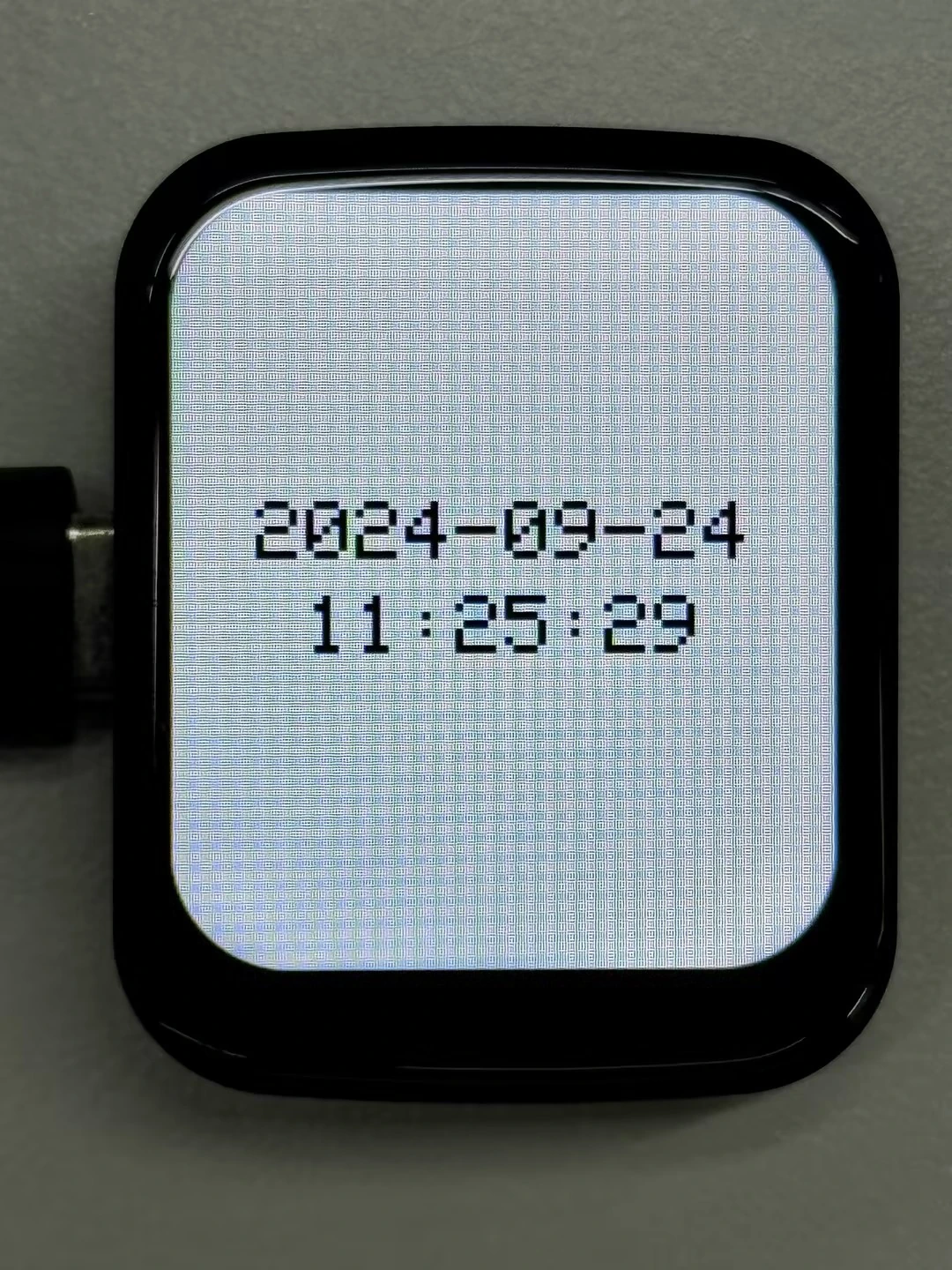
06_GFX_PCF85063_simpleTime
This example demonstrates using the PCF85063 RTC module to display the current date and time on the ST7789 display. It retrieves the time every second and updates the centered display only when the value changes.
Code
06_GFX_PCF85063_simpleTime.ino
#include <Arduino.h>
#include "Arduino_GFX_Library.h"
#include "pin_config.h"
#include "SensorPCF85063.hpp"
#include <Wire.h>

#include "HWCDC.h"
HWCDC USBSerial;

SensorPCF85063 rtc;
uint32_t lastMillis;
char previousTimeString[20] = "";
Arduino_DataBus *bus = new Arduino_ESP32SPI(LCD_DC, LCD_CS, LCD_SCK, LCD_MOSI);

Arduino_GFX *gfx = new Arduino_ST7789(bus, LCD_RST /* RST */,
                                      0 /* rotation */, true /* IPS */, LCD_WIDTH, LCD_HEIGHT, 0, 20, 0, 0);

const uint8_t TEXT_SIZE = 3;
const int16_t FONT_WIDTH = 6;
const int16_t FONT_HEIGHT = 8;
const int16_t LINE_GAP = 10;

int16_t getCenteredX(const char *text, uint8_t textSize) {
  int16_t textWidth = strlen(text) * FONT_WIDTH * textSize;
  int16_t x = (LCD_WIDTH - textWidth) / 2;
  return x > 0 ? x : 0;
}

int16_t getTextBlockY() {
  int16_t lineHeight = FONT_HEIGHT * TEXT_SIZE;
  int16_t totalHeight = (lineHeight * 2) + LINE_GAP;
  return (LCD_HEIGHT - totalHeight) / 2;
}

void drawCenteredText(const char *text, int16_t y) {
  gfx->setCursor(getCenteredX(text, TEXT_SIZE), y);
  gfx->println(text);
}

void setup() {
  USBSerial.begin(115200);
  if (!rtc.begin(Wire, IIC_SDA, IIC_SCL)) {
    USBSerial.println("Failed to find PCF85063 - check your wiring!");
    while (1) {
      delay(1000);
    }
  }

  uint16_t year = 2024;
  uint8_t month = 9;
  uint8_t day = 24;
  uint8_t hour = 11;
  uint8_t minute = 24;
  uint8_t second = 30;

  rtc.setDateTime(year, month, day, hour, minute, second);
  gfx->begin();
  gfx->fillScreen(RGB565_WHITE);
  pinMode(LCD_BL, OUTPUT);
  digitalWrite(LCD_BL, HIGH);
}

void loop() {

  if (millis() - lastMillis > 1000) {
    lastMillis = millis();

    RTC_DateTime datetime = rtc.getDateTime();

    char dateString[11];
    char timeString[9];
    char dateTimeString[20];

    sprintf(dateString, "%04d-%02d-%02d", datetime.getYear(), datetime.getMonth(), datetime.getDay());
    sprintf(timeString, "%02d:%02d:%02d", datetime.getHour(), datetime.getMinute(), datetime.getSecond());
    sprintf(dateTimeString, "%s %s", dateString, timeString);

    // Only update the time if it has changed
    if (strcmp(dateTimeString, previousTimeString) != 0) {
      int16_t lineHeight = FONT_HEIGHT * TEXT_SIZE;
      int16_t dateY = getTextBlockY();
      int16_t timeY = dateY + lineHeight + LINE_GAP;

      gfx->fillRect(0, dateY - 4, LCD_WIDTH, (lineHeight * 2) + LINE_GAP + 8, RGB565_WHITE);
      gfx->setTextColor(RGB565_BLACK);
      gfx->setTextSize(TEXT_SIZE);

      drawCenteredText(dateString, dateY);
      drawCenteredText(timeString, timeY);

      strcpy(previousTimeString, dateTimeString);
    }
  }
}
Code Analysis
loop():- Gets the current time and reads the date and time fields through the
getYear(),getMonth(), and related APIs; - Generates separate date and time strings, then combines them into
dateTimeStringfor change detection; - When the date or time changes, clears only the centered text area to avoid full-screen flicker;
- Uses
getTextBlockY()to calculate the vertical starting point for the two centered lines, then callsdrawCenteredText()to display the date and time; - Copies the current date-time string to
previousTimeStringfor the next comparison.
- Gets the current time and reads the date and time fields through the
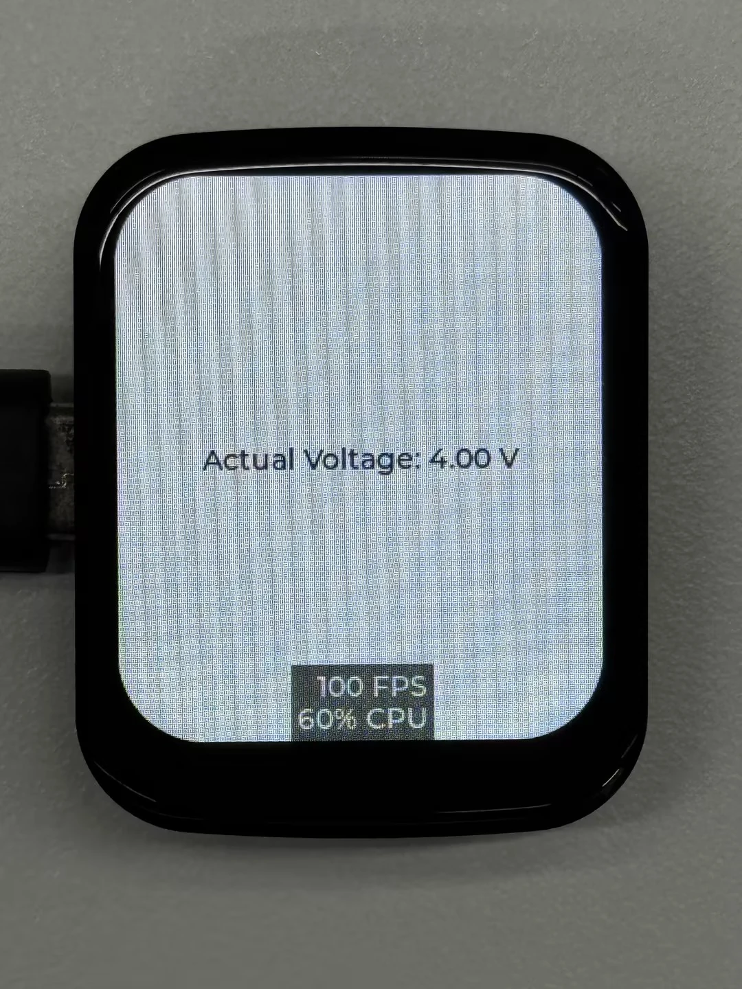
07_LVGL_Measuring_voltage
This example demonstrates how to use the LVGL library and the Arduino GFX library to implement display text updates and voltage measurement. The code initializes the ST7789 display, creates a label at the center of the screen, periodically reads the actual voltage value from the voltage divider, and updates the label to show the latest voltage information.
Code
07_LVGL_Measuring_voltage.ino
#include <lvgl.h>
#include "Arduino_GFX_Library.h"
#include "lv_conf.h"
#include "demos/lv_demos.h"
#include "pin_config.h"

/*Using LVGL with Arduino requires some extra steps:
 *Be sure to read the docs here: https://lvgl.io/docs/open/integration/frameworks/arduino  */

#define EXAMPLE_LVGL_TICK_PERIOD_MS 2

/* Change to your screen resolution */
static const uint16_t screenWidth = 240;
static const uint16_t screenHeight = 280;

static lv_disp_draw_buf_t draw_buf;
static lv_color_t buf[screenWidth * screenHeight / 10];

const int voltageDividerPin = 1;  // GPIO1 pin
float vRef = 3.3;                 // Power supply voltage of ESP32-S3 (unit: volts)
float R1 = 200000.0;              // Resistance value of the first resistor (unit: ohms)
float R2 = 100000.0;              // Resistance value of the second resistor (unit: ohms)

lv_obj_t *label;  // Global label object

Arduino_DataBus *bus = new Arduino_ESP32SPI(LCD_DC, LCD_CS, LCD_SCK, LCD_MOSI);

Arduino_GFX *gfx = new Arduino_ST7789(bus, LCD_RST /* RST */,
                                      0 /* rotation */, true /* IPS */, LCD_WIDTH, LCD_HEIGHT, 0, 20, 0, 0);

#if LV_USE_LOG != 0
/* Serial debugging */
void my_print(const char *buf) {
  Serial.printf(buf);
  Serial.flush();
}
#endif

/* Display flushing */
void my_disp_flush(lv_disp_drv_t *disp, const lv_area_t *area, lv_color_t *color_p) {
  uint32_t w = (area->x2 - area->x1 + 1);
  uint32_t h = (area->y2 - area->y1 + 1);

#if (LV_COLOR_16_SWAP != 0)
  gfx->draw16bitBeRGBBitmap(area->x1, area->y1, (uint16_t *)&color_p->full, w, h);
#else
  gfx->draw16bitRGBBitmap(area->x1, area->y1, (uint16_t *)&color_p->full, w, h);
#endif

  lv_disp_flush_ready(disp);
}

void example_increase_lvgl_tick(void *arg) {
  /* Tell LVGL how many milliseconds has elapsed */
  lv_tick_inc(EXAMPLE_LVGL_TICK_PERIOD_MS);
}

static uint8_t count = 0;
void example_increase_reboot(void *arg) {
  count++;
  if (count == 30) {
    esp_restart();
  }
}

void setup() {
  Serial.begin(115200); /* prepare for possible serial debug */
  pinMode(voltageDividerPin, INPUT);

  String LVGL_Arduino = "Hello Arduino! ";
  LVGL_Arduino += String('V') + lv_version_major() + "." + lv_version_minor() + "." + lv_version_patch();

  Serial.println(LVGL_Arduino);
  Serial.println("I am LVGL_Arduino");

  lv_init();

#if LV_USE_LOG != 0
  lv_log_register_print_cb(my_print); /* register print function for debugging */
#endif

  gfx->begin();
  pinMode(LCD_BL, OUTPUT);
  digitalWrite(LCD_BL, HIGH);

  lv_disp_draw_buf_init(&draw_buf, buf, NULL, screenWidth * screenHeight / 10);

  /*Initialize the display*/
  static lv_disp_drv_t disp_drv;
  lv_disp_drv_init(&disp_drv);
  /*Change the following line to your display resolution*/
  disp_drv.hor_res = screenWidth;
  disp_drv.ver_res = screenHeight;
  disp_drv.flush_cb = my_disp_flush;
  disp_drv.draw_buf = &draw_buf;
  lv_disp_drv_register(&disp_drv);

  const esp_timer_create_args_t lvgl_tick_timer_args = {
   .callback = &example_increase_lvgl_tick,
   .name = "lvgl_tick"
  };

  const esp_timer_create_args_t reboot_timer_args = {
   .callback = &example_increase_reboot,
   .name = "reboot"
  };

  esp_timer_handle_t lvgl_tick_timer = NULL;
  esp_timer_create(&lvgl_tick_timer_args, &lvgl_tick_timer);
  esp_timer_start_periodic(lvgl_tick_timer, EXAMPLE_LVGL_TICK_PERIOD_MS * 1000);

  // esp_timer_handle_t reboot_timer = NULL;
  // esp_timer_create(&reboot_timer_args, &reboot_timer);
  // esp_timer_start_periodic(reboot_timer, 2000 * 1000);

  /* Create label */
  label = lv_label_create(lv_scr_act());
  lv_label_set_text(label, "Initializing...");
  lv_obj_align(label, LV_ALIGN_CENTER, 0, 0);

  Serial.println("Setup done");
}

void loop() {
  lv_timer_handler(); /* let the GUI do its work */
  delay(5);

  // Read ADC value
  int adcValue = analogRead(voltageDividerPin);

  // Convert to voltage
  float voltage = (float)adcValue * (vRef / 4095.0);

  // Apply the voltage divider formula to calculate the actual voltage
  float actualVoltage = voltage * ((R1 + R2) / R2);

  // Print the actual voltage
  Serial.print("Actual Voltage: ");
  Serial.print(actualVoltage);
  Serial.println(" V");

  // Update label content
  String voltageStr = "Actual Voltage: " + String(actualVoltage) + " V";
  lv_label_set_text(label, voltageStr.c_str());
}
Code Analysis
my_print(): Used for LVGL log output; if LVGL logging is enabled, this function prints log messages to the serial port.my_disp_flush(): Responsible for flushing the LVGL drawing buffer contents to the display.example_increase_lvgl_tick(): Timer callback function to inform LVGL of the passage of time.example_increase_reboot(): Another timer callback function that counts and may trigger a system restart after a certain number of calls.
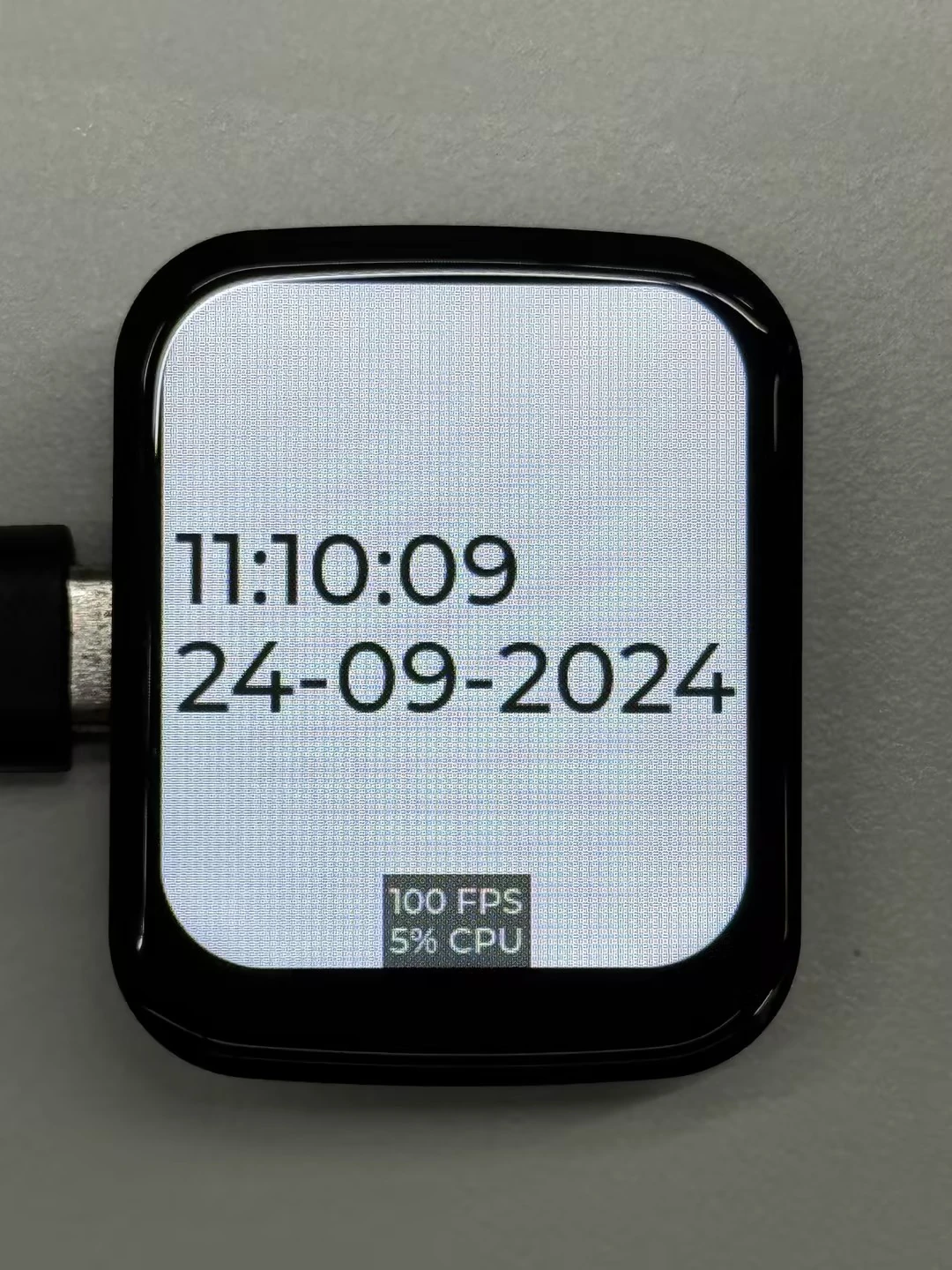
08_LVGL_PCF85063_simpleTime
This example demonstrates using the PCF85063 RTC module under LVGL to display the current time on the ST7789 display. It retrieves the time every second and updates the display only when the time changes.
Code
08_LVGL_PCF85063_simpleTime.ino
#include <lvgl.h>
#include "Arduino_GFX_Library.h"
#include "pin_config.h"
#include "lv_conf.h"
#include <Wire.h>
#include <SPI.h>
#include <Arduino.h>
#include "SensorPCF85063.hpp"
#include "HWCDC.h"

HWCDC USBSerial;
#define EXAMPLE_LVGL_TICK_PERIOD_MS 2

static lv_disp_draw_buf_t draw_buf;
static lv_color_t buf[LCD_WIDTH * LCD_HEIGHT / 10];

lv_obj_t *label;  // Global label object
SensorPCF85063 rtc;
uint32_t lastMillis;

Arduino_DataBus *bus = new Arduino_ESP32SPI(LCD_DC, LCD_CS, LCD_SCK, LCD_MOSI);

Arduino_GFX *gfx = new Arduino_ST7789(bus, LCD_RST /* RST */,
                                      0 /* rotation */, true /* IPS */, LCD_WIDTH, LCD_HEIGHT, 0, 20, 0, 0);
#if LV_USE_LOG != 0
/* Serial debugging */
void my_print(const char *buf) {
  USBSerial.printf(buf);
  USBSerial.flush();
}
#endif

/* Display flushing */
void my_disp_flush(lv_disp_drv_t *disp, const lv_area_t *area, lv_color_t *color_p) {
  uint32_t w = (area->x2 - area->x1 + 1);
  uint32_t h = (area->y2 - area->y1 + 1);

#if (LV_COLOR_16_SWAP != 0)
  gfx->draw16bitBeRGBBitmap(area->x1, area->y1, (uint16_t *)&color_p->full, w, h);
#else
  gfx->draw16bitRGBBitmap(area->x1, area->y1, (uint16_t *)&color_p->full, w, h);
#endif

  lv_disp_flush_ready(disp);
}

void example_increase_lvgl_tick(void *arg) {
  /* Tell LVGL how many milliseconds has elapsed */
  lv_tick_inc(EXAMPLE_LVGL_TICK_PERIOD_MS);
}

static uint8_t count = 0;
void example_increase_reboot(void *arg) {
  count++;
  if (count == 30) {
    esp_restart();
  }
}

void setup() {
  USBSerial.begin(115200); /* prepare for possible serial debug */
  if (!rtc.begin(Wire, IIC_SDA, IIC_SCL)) {
    USBSerial.println("Failed to find PCF85063 - check your wiring!");
    while (1) {
      delay(1000);
    }
  }

  uint16_t year = 2024;
  uint8_t month = 9;
  uint8_t day = 24;
  uint8_t hour = 11;
  uint8_t minute = 9;
  uint8_t second = 41;

  rtc.setDateTime(year, month, day, hour, minute, second);


  gfx->begin();
  pinMode(LCD_BL, OUTPUT);
  digitalWrite(LCD_BL, HIGH);

  String LVGL_Arduino = "Hello Arduino! ";
  LVGL_Arduino += String('V') + lv_version_major() + "." + lv_version_minor() + "." + lv_version_patch();

  USBSerial.println(LVGL_Arduino);
  USBSerial.println("I am LVGL_Arduino");

  lv_init();

#if LV_USE_LOG != 0
  lv_log_register_print_cb(my_print); /* register print function for debugging */
#endif


  lv_disp_draw_buf_init(&draw_buf, buf, NULL, LCD_WIDTH * LCD_HEIGHT / 10);

  /*Initialize the display*/
  static lv_disp_drv_t disp_drv;
  lv_disp_drv_init(&disp_drv);
  /*Change the following line to your display resolution*/
  disp_drv.hor_res = LCD_WIDTH;
  disp_drv.ver_res = LCD_HEIGHT;
  disp_drv.flush_cb = my_disp_flush;
  disp_drv.draw_buf = &draw_buf;
  lv_disp_drv_register(&disp_drv);

  // lv_obj_t *label = lv_label_create(lv_scr_act());
  // lv_label_set_text(label, "Hello Ardino and LVGL!");
  // lv_obj_align(label, LV_ALIGN_CENTER, 0, 0);

  const esp_timer_create_args_t lvgl_tick_timer_args = {
    .callback = &example_increase_lvgl_tick,
    .name = "lvgl_tick"
  };

  const esp_timer_create_args_t reboot_timer_args = {
    .callback = &example_increase_reboot,
    .name = "reboot"
  };

  esp_timer_handle_t lvgl_tick_timer = NULL;
  esp_timer_create(&lvgl_tick_timer_args, &lvgl_tick_timer);
  esp_timer_start_periodic(lvgl_tick_timer, EXAMPLE_LVGL_TICK_PERIOD_MS * 1000);

  label = lv_label_create(lv_scr_act());
  lv_label_set_text(label, "Initializing...");
  lv_obj_align(label, LV_ALIGN_CENTER, 0, 0);
}

void loop() {
  lv_timer_handler(); /* let the GUI do its work */
  delay(5);

  if (millis() - lastMillis > 1000) {
    lastMillis = millis();
    RTC_DateTime datetime = rtc.getDateTime();
    USBSerial.printf(" Year :");
    USBSerial.print(datetime.getYear());
    USBSerial.printf(" Month:");
    USBSerial.print(datetime.getMonth());
    USBSerial.printf(" Day :");
    USBSerial.print(datetime.getDay());
    USBSerial.printf(" Hour:");
    USBSerial.print(datetime.getHour());
    USBSerial.printf(" Minute:");
    USBSerial.print(datetime.getMinute());
    USBSerial.printf(" Sec :");
    USBSerial.println(datetime.getSecond());

    char buf[32];
    snprintf(buf, sizeof(buf), "%02d:%02d:%02d\n%02d-%02d-%04d",
             datetime.getHour(), datetime.getMinute(), datetime.getSecond(),
             datetime.getDay(), datetime.getMonth(), datetime.getYear());

    // Update label with current time
    lv_label_set_text(label, buf);
    lv_obj_set_style_text_font(label, &lv_font_montserrat_40, LV_PART_MAIN);
  }
  delay(20);
}
Code Analysis
-
setup():- Initializes serial communication at 115200 baud for possible serial debugging;
- Attempts to connect to the PCF85063 real-time clock chip; if it fails, enters an infinite loop;
- Sets the initial RTC time to 2024-09-24 11:09:41;
- Initializes the display and sets screen brightness;
- Initializes LVGL and registers a log output function (if logging is enabled);
- Configures the LVGL display driver and drawing buffer;
- Creates a timer to periodically trigger LVGL tick updates;
- Creates a label and sets its initial text to "Initializing...".
-
loop():- Calls
lv_timer_handlerto let LVGL handle GUI tasks; - Every second, checks whether the time has been updated; if so, reads the RTC data through the
RTC_DateTimegetter APIs, outputs it via serial, formats it as a string, updates the label's text, and sets the label's font tolv_font_montserrat_40.
- Calls
09_LVGL_Keys_Bee
This example demonstrates how to use the LVGL library in combination with Arduino and ESP32 to implement a button response system with a simple GUI interaction. The code allows the user to detect single-click, double-click, and long-press events via a button and displays corresponding output on the connected LCD screen.
Specific functionalities include: displaying the words "Single Click", "Double Click", and "Long Press" on the screen using trigger actions, and enabling the buzzer on a long press. The program refreshes the screen using LVGL's drawing functions and improves button recognition accuracy with a simple debouncing mechanism. Additionally, an auto-restart mechanism is provided for device maintenance during long-run operation.

Code
09_LVGL_Keys_Bee.ino
#error "If the key fails, change USE_NEW_PIN_CONFIG to 1 to use the new pin configuration. Comment this line as you run the code"

#include <lvgl.h>
#include "Arduino_GFX_Library.h"
#include "lv_conf.h"
#include "demos/lv_demos.h"
#include "pin_config.h"
#include <Wire.h>
#include "HWCDC.h"

HWCDC USBSerial;
/*To use the built-in examples and demos of LVGL uncomment the includes below respectively.
 *You also need to copy `lvgl/examples` to `lvgl/src/examples`. Similarly for the demos `lvgl/demos` to `lvgl/src/demos`.
 Note that the `lv_examples` library is for LVGL v7 and you shouldn't install it for this version (since LVGL v8)
 as the examples and demos are now part of the main LVGL library. */

#define EXAMPLE_LVGL_TICK_PERIOD_MS 2
#define USE_NEW_PIN_CONFIG 0

#if (USE_NEW_PIN_CONFIG)
// New pin configuration
const int inputPin = 40;   // Define GPIO40 as input
const int outputPin = 41;  // Define GPIO41 as output
const int beePin = 42;     // Define GPIO42 for buzzer
#else
// Existing pin configuration
const int inputPin = 36;   // Define GPIO36 as input
const int outputPin = 35;  // Define GPIO35 as output
const int beePin = 33;     // Define GPIO33 for buzzer
#endif

bool buttonState = false;
bool lastButtonState = false;
unsigned long lastDebounceTime = 0;
unsigned long debounceDelay = 50;
unsigned long lastClickTime = 0;
unsigned long clickInterval = 500;       // Double-click interval
unsigned long longPressDuration = 1000;  // Long press duration

bool longPressDetected = false;
bool doubleClickDetected = false;
bool clickDetected = false;

/* Change to your screen resolution */
static const uint16_t screenWidth = 240;
static const uint16_t screenHeight = 280;

static lv_disp_draw_buf_t draw_buf;
static lv_color_t buf[screenWidth * screenHeight / 10];

lv_obj_t *label;  // Global label object

Arduino_DataBus *bus = new Arduino_ESP32SPI(LCD_DC, LCD_CS, LCD_SCK, LCD_MOSI);

Arduino_GFX *gfx = new Arduino_ST7789(bus, LCD_RST /* RST */,
                                      0 /* rotation */, true /* IPS */, LCD_WIDTH, LCD_HEIGHT, 0, 20, 0, 0);

#if LV_USE_LOG != 0
/* USBSerial debugging */
void my_print(const char *buf) {
  USBSerial.printf(buf);
  USBSerial.flush();
}
#endif

/* Display flushing */
void my_disp_flush(lv_disp_drv_t *disp, const lv_area_t *area, lv_color_t *color_p) {
  uint32_t w = (area->x2 - area->x1 + 1);
  uint32_t h = (area->y2 - area->y1 + 1);

#if (LV_COLOR_16_SWAP != 0)
  gfx->draw16bitBeRGBBitmap(area->x1, area->y1, (uint16_t *)&color_p->full, w, h);
#else
  gfx->draw16bitRGBBitmap(area->x1, area->y1, (uint16_t *)&color_p->full, w, h);
#endif

  lv_disp_flush_ready(disp);
}

void example_increase_lvgl_tick(void *arg) {
  /* Tell LVGL how many milliseconds has elapsed */
  lv_tick_inc(EXAMPLE_LVGL_TICK_PERIOD_MS);
}

static uint8_t count = 0;
void example_increase_reboot(void *arg) {
  count++;
  if (count == 30) {
    esp_restart();
  }
}

void setup() {
  pinMode(inputPin, INPUT);
  pinMode(outputPin, OUTPUT);
  pinMode(beePin, OUTPUT);
  digitalWrite(outputPin, HIGH);  // Initialize output pin to HIGH

  gfx->begin();
  pinMode(LCD_BL, OUTPUT);
  digitalWrite(LCD_BL, HIGH);

  String LVGL_Arduino = "Hello Arduino! ";
  LVGL_Arduino += String('V') + lv_version_major() + "." + lv_version_minor() + "." + lv_version_patch();

  USBSerial.println(LVGL_Arduino);
  USBSerial.println("I am LVGL_Arduino");

  lv_init();

#if LV_USE_LOG != 0
  lv_log_register_print_cb(my_print); /* register print function for debugging */
#endif

  lv_disp_draw_buf_init(&draw_buf, buf, NULL, screenWidth * screenHeight / 10);

  /*Initialize the display*/
  static lv_disp_drv_t disp_drv;
  lv_disp_drv_init(&disp_drv);
  /*Change the following line to your display resolution*/
  disp_drv.hor_res = screenWidth;
  disp_drv.ver_res = screenHeight;
  disp_drv.flush_cb = my_disp_flush;
  disp_drv.draw_buf = &draw_buf;
  lv_disp_drv_register(&disp_drv);

  const esp_timer_create_args_t lvgl_tick_timer_args = {
    .callback = &example_increase_lvgl_tick,
    .name = "lvgl_tick"
  };

  const esp_timer_create_args_t reboot_timer_args = {
    .callback = &example_increase_reboot,
    .name = "reboot"
  };

  esp_timer_handle_t lvgl_tick_timer = NULL;
  esp_timer_create(&lvgl_tick_timer_args, &lvgl_tick_timer);
  esp_timer_start_periodic(lvgl_tick_timer, EXAMPLE_LVGL_TICK_PERIOD_MS * 1000);

  // esp_timer_handle_t reboot_timer = NULL;
  // esp_timer_create(&reboot_timer_args, &reboot_timer);
  // esp_timer_start_periodic(reboot_timer, 2000 * 1000);

  label = lv_label_create(lv_scr_act());
  lv_label_set_text(label, "Initializing...");
  lv_obj_align(label, LV_ALIGN_CENTER, 0, 0);

  USBSerial.println("Setup done");
}

void loop() {
  lv_timer_handler(); /* let the GUI do its work */
  delay(5);

  int reading = digitalRead(inputPin);
  // Debounce processing
  if (reading != lastButtonState) {
    lastDebounceTime = millis();
  }
  if ((millis() - lastDebounceTime) > debounceDelay) {
    if (reading != buttonState) {
      buttonState = reading;

      if (buttonState == LOW) {
        // Operation when button is pressed
        unsigned long now = millis();
        if (now - lastClickTime < clickInterval && !longPressDetected) {
          lv_label_set_text(label, "Double Click");
          // Double click detected
          printf("Double Click\n");
          doubleClickDetected = true;
        }else{
          // Single click detected
          if (!longPressDetected && !doubleClickDetected) {
            lv_label_set_text(label, "Single Click");
            printf("Single Click\n");
            clickDetected = true;
          }
        }
        lastClickTime = now;

        delay(100);  // Used to eliminate button noise
      }else{
        // Operation when button is released
        if (longPressDetected) {
          lv_label_set_text(label, "Long Press Released");

          // Set GPIO35 output to low level after long pressing the button and releasing it
          printf("Long Press Released\n");
          noTone(beePin);
          digitalWrite(outputPin, LOW);  // Set GPIO35 output to low level
          longPressDetected = false;     // Reset long press detection flag
        }
        clickDetected = false;
        doubleClickDetected = false;
      }
    }
  }

  // Check if the button is in long press state
  if (buttonState == LOW && (millis() - lastDebounceTime >= longPressDuration)) {
    lv_label_set_text(label, "Long Press");
    // Long press button
    printf("Long Press\n");
    tone(beePin, 2000);
    longPressDetected = true;     // Set long press detection flag
    clickDetected = false;        // Reset single click detection flag
    doubleClickDetected = false;  // Reset double click detection flag
  }
  lastButtonState = reading;
}
Code Analysis
loop():- Calls
lv_timer_handlerto let LVGL handle GUI tasks; - Reads the state of the input pin and performs debouncing;
- Based on the button state (pressed or released) and timing, determines whether a single-click, double-click, or long-press event occurred, and updates the label text on the display accordingly;
- For a long press, activates the buzzer; when released, stops the buzzer and sets a specific output pin to low.
- Calls
10_LVGL_QMI8658_ui
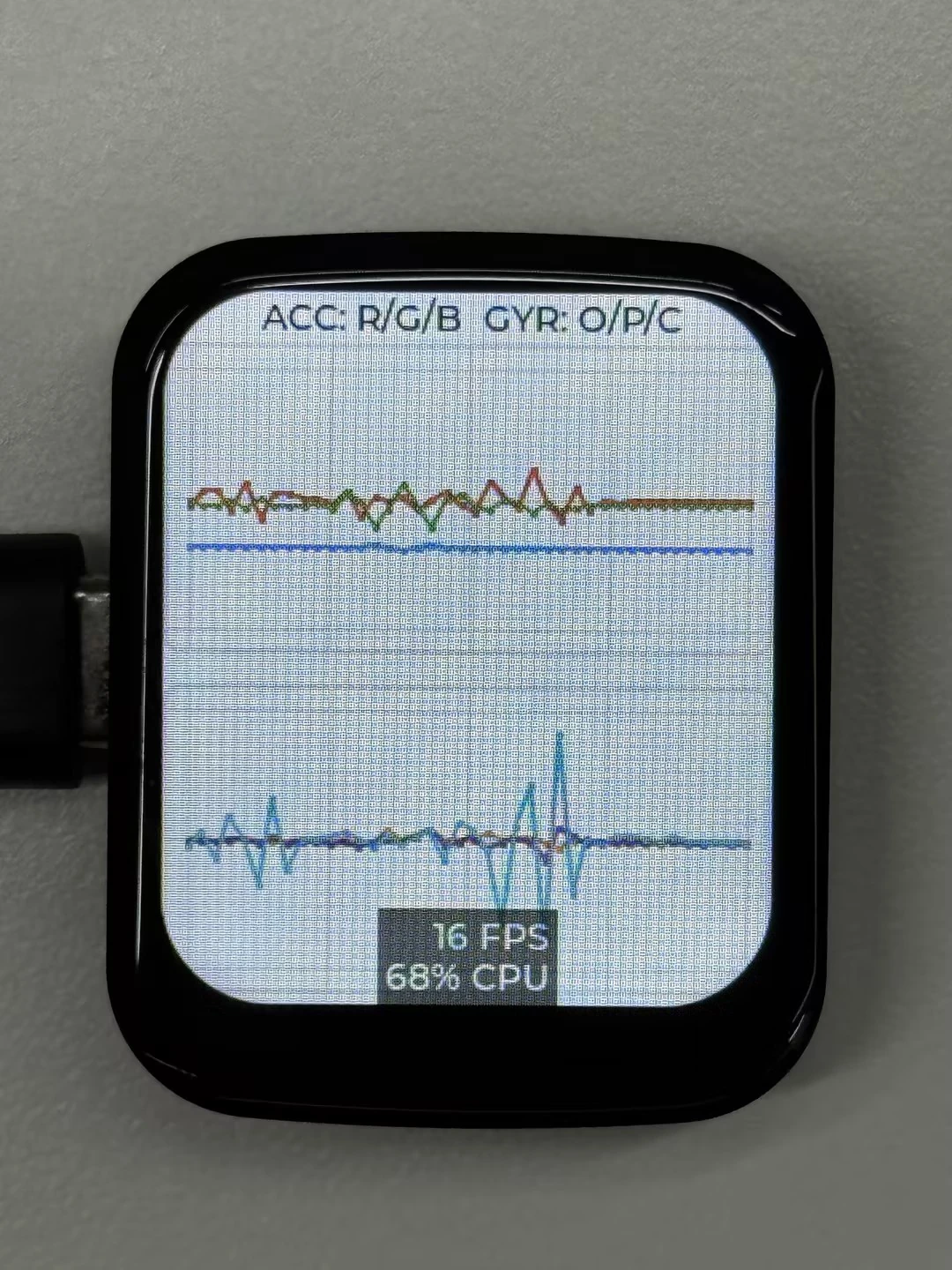
This example demonstrates using LVGL for graphical display and communicating with the QMI8658 IMU to obtain accelerometer and gyroscope data. The top of the interface shows the curve color legend, while the middle and lower areas plot the three-axis accelerometer and gyroscope curves.
Code
10_LVGL_QMI8658_ui.ino
#include <lvgl.h>
#include "Arduino_GFX_Library.h"
#include "pin_config.h"
#include "lv_conf.h"
#include <Arduino.h>
#include <Wire.h>
#include <math.h>
#include "SensorQMI8658.hpp"
#include "HWCDC.h"

HWCDC USBSerial;

#define EXAMPLE_LVGL_TICK_PERIOD_MS 2
#define ACC_CHART_SCALE 100
#define GYR_CHART_SCALE 10
#define GYR_CHART_RANGE_DPS 256
#define CHART_POINT_COUNT 40
#define CHART_POINT_SIZE 2

static lv_disp_draw_buf_t draw_buf;
static lv_color_t buf[LCD_WIDTH * LCD_HEIGHT / 10];

SensorQMI8658 qmi;

IMUdata acc;
IMUdata gyr;

lv_obj_t *label;                  // Global label object
lv_obj_t *acc_chart;              // Acceleration chart object
lv_obj_t *gyr_chart;              // Gyroscope chart object
lv_chart_series_t *acc_series_x;  // Acceleration X series
lv_chart_series_t *acc_series_y;  // Acceleration Y series
lv_chart_series_t *acc_series_z;  // Acceleration Z series
lv_chart_series_t *gyr_series_x;  // Gyroscope X series
lv_chart_series_t *gyr_series_y;  // Gyroscope Y series
lv_chart_series_t *gyr_series_z;  // Gyroscope Z series

Arduino_DataBus *bus = new Arduino_ESP32SPI(LCD_DC, LCD_CS, LCD_SCK, LCD_MOSI);

Arduino_GFX *gfx = new Arduino_ST7789(bus, LCD_RST /* RST */,
                                      0 /* rotation */, true /* IPS */, LCD_WIDTH, LCD_HEIGHT, 0, 20, 0, 0);

#if LV_USE_LOG != 0
/* Serial debugging */
void my_print(const char *buf) {
  USBSerial.printf("%s", buf);
  USBSerial.flush();
}
#endif

/* Display flushing */
void my_disp_flush(lv_disp_drv_t *disp, const lv_area_t *area, lv_color_t *color_p) {
  uint32_t w = (area->x2 - area->x1 + 1);
  uint32_t h = (area->y2 - area->y1 + 1);

#if (LV_COLOR_16_SWAP != 0)
  gfx->draw16bitBeRGBBitmap(area->x1, area->y1, (uint16_t *)&color_p->full, w, h);
#else
  gfx->draw16bitRGBBitmap(area->x1, area->y1, (uint16_t *)&color_p->full, w, h);
#endif

  lv_disp_flush_ready(disp);
}

void example_increase_lvgl_tick(void *arg) {
  /* Tell LVGL how many milliseconds has elapsed */
  lv_tick_inc(EXAMPLE_LVGL_TICK_PERIOD_MS);
}

static lv_coord_t accel_to_chart_value(float value) {
  return (lv_coord_t)lroundf(value * ACC_CHART_SCALE);
}

static lv_coord_t gyro_to_chart_value(float value) {
  return (lv_coord_t)lroundf(value * GYR_CHART_SCALE);
}


void setup() {
  USBSerial.begin(115200); /* prepare for possible serial debug */

  // pinMode(LCD_EN, OUTPUT);
  // digitalWrite(LCD_EN, HIGH);

  gfx->begin();
  pinMode(LCD_BL, OUTPUT);
  pinMode(38, OUTPUT);
  digitalWrite(LCD_BL, HIGH);
  digitalWrite(38, HIGH);
  String LVGL_Arduino = "Hello Arduino! ";
  LVGL_Arduino += String('V') + lv_version_major() + "." + lv_version_minor() + "." + lv_version_patch();

  USBSerial.println(LVGL_Arduino);
  USBSerial.println("I am LVGL_Arduino");

  lv_init();

#if LV_USE_LOG != 0
  lv_log_register_print_cb(my_print); /* register print function for debugging */
#endif

  lv_disp_draw_buf_init(&draw_buf, buf, NULL, LCD_WIDTH * LCD_HEIGHT / 10);

  /*Initialize the display*/
  static lv_disp_drv_t disp_drv;
  lv_disp_drv_init(&disp_drv);
  /*Change the following line to your display resolution*/
  disp_drv.hor_res = LCD_WIDTH;
  disp_drv.ver_res = LCD_HEIGHT;
  disp_drv.flush_cb = my_disp_flush;
  disp_drv.draw_buf = &draw_buf;
  lv_disp_drv_register(&disp_drv);

  label = lv_label_create(lv_scr_act());
  lv_label_set_text(label, "Hello Arduino and LVGL!");
  lv_obj_align(label, LV_ALIGN_CENTER, 0, 0);

  const esp_timer_create_args_t lvgl_tick_timer_args = {
    .callback = &example_increase_lvgl_tick,
    .name = "lvgl_tick"
  };

  esp_timer_handle_t lvgl_tick_timer = NULL;
  esp_timer_create(&lvgl_tick_timer_args, &lvgl_tick_timer);
  esp_timer_start_periodic(lvgl_tick_timer, EXAMPLE_LVGL_TICK_PERIOD_MS * 1000);

  lv_label_set_text(label, "ACC: R/G/B  GYR: O/P/C");
  lv_obj_align(label, LV_ALIGN_TOP_MID, 0, 2);

  /* Create acceleration chart */
  acc_chart = lv_chart_create(lv_scr_act());
  lv_obj_set_size(acc_chart, 240, 122);
  lv_obj_align(acc_chart, LV_ALIGN_TOP_MID, 0, 20);
  lv_chart_set_type(acc_chart, LV_CHART_TYPE_LINE);
  lv_chart_set_range(acc_chart, LV_CHART_AXIS_PRIMARY_Y,
                     -3 * ACC_CHART_SCALE, 3 * ACC_CHART_SCALE);
  lv_chart_set_point_count(acc_chart, CHART_POINT_COUNT);
  lv_obj_set_style_size(acc_chart, CHART_POINT_SIZE, LV_PART_INDICATOR);
  acc_series_x = lv_chart_add_series(acc_chart, lv_palette_main(LV_PALETTE_RED), LV_CHART_AXIS_PRIMARY_Y);
  acc_series_y = lv_chart_add_series(acc_chart, lv_palette_main(LV_PALETTE_GREEN), LV_CHART_AXIS_PRIMARY_Y);
  acc_series_z = lv_chart_add_series(acc_chart, lv_palette_main(LV_PALETTE_BLUE), LV_CHART_AXIS_PRIMARY_Y);

  /* Create gyroscope chart */
  gyr_chart = lv_chart_create(lv_scr_act());
  lv_obj_set_size(gyr_chart, 240, 122);
  lv_obj_align(gyr_chart, LV_ALIGN_TOP_MID, 0, 154);
  lv_chart_set_type(gyr_chart, LV_CHART_TYPE_LINE);
  lv_chart_set_range(gyr_chart, LV_CHART_AXIS_PRIMARY_Y,
                     -GYR_CHART_RANGE_DPS * GYR_CHART_SCALE,
                     GYR_CHART_RANGE_DPS * GYR_CHART_SCALE);
  lv_chart_set_point_count(gyr_chart, CHART_POINT_COUNT);
  lv_obj_set_style_size(gyr_chart, CHART_POINT_SIZE, LV_PART_INDICATOR);
  gyr_series_x = lv_chart_add_series(gyr_chart, lv_palette_main(LV_PALETTE_ORANGE), LV_CHART_AXIS_PRIMARY_Y);
  gyr_series_y = lv_chart_add_series(gyr_chart, lv_palette_main(LV_PALETTE_PURPLE), LV_CHART_AXIS_PRIMARY_Y);
  gyr_series_z = lv_chart_add_series(gyr_chart, lv_palette_main(LV_PALETTE_CYAN), LV_CHART_AXIS_PRIMARY_Y);

  USBSerial.println("Setup done");

  if (!qmi.begin(Wire, QMI8658_L_SLAVE_ADDRESS, IIC_SDA, IIC_SCL)) {

    while (1) {
      delay(1000);
    }
  }

  /* Get chip id */
  USBSerial.println(qmi.getChipID());

  qmi.configAccelerometer(
    SensorQMI8658::ACC_RANGE_4G,
    SensorQMI8658::ACC_ODR_1000Hz,
    SensorQMI8658::LPF_MODE_0);

  qmi.configGyroscope(
    SensorQMI8658::GYR_RANGE_256DPS,
    SensorQMI8658::GYR_ODR_896_8Hz,
    SensorQMI8658::LPF_MODE_3);

  qmi.enableGyroscope();
  qmi.enableAccelerometer();

  qmi.dumpCtrlRegister();

  USBSerial.println("Read data now...");
}

void loop() {
  lv_timer_handler(); /* let the GUI do its work */
  delay(5);

  if (qmi.getDataReady()) {
    if (qmi.getAccelerometer(acc.x, acc.y, acc.z)) {
      USBSerial.print("{ACCEL: ");
      USBSerial.print(acc.x);
      USBSerial.print(",");
      USBSerial.print(acc.y);
      USBSerial.print(",");
      USBSerial.print(acc.z);
      USBSerial.println("}");

      // Update chart with new accelerometer data
      lv_chart_set_next_value(acc_chart, acc_series_x, accel_to_chart_value(acc.x));
      lv_chart_set_next_value(acc_chart, acc_series_y, accel_to_chart_value(acc.y));
      lv_chart_set_next_value(acc_chart, acc_series_z, accel_to_chart_value(acc.z));
    }

    if (qmi.getGyroscope(gyr.x, gyr.y, gyr.z)) {
      USBSerial.print("{GYRO: ");
      USBSerial.print(gyr.x);
      USBSerial.print(",");
      USBSerial.print(gyr.y);
      USBSerial.print(",");
      USBSerial.print(gyr.z);
      USBSerial.println("}");

      // Update chart with new gyroscope data
      lv_chart_set_next_value(gyr_chart, gyr_series_x, gyro_to_chart_value(gyr.x));
      lv_chart_set_next_value(gyr_chart, gyr_series_y, gyro_to_chart_value(gyr.y));
      lv_chart_set_next_value(gyr_chart, gyr_series_z, gyro_to_chart_value(gyr.z));
    }
  }
  delay(20);  // Increase the frequency of data polling
}
Code Analysis
-
my_disp_flush():- This function is the refresh funtion of LVGL display driver. It is responsible for refreshing the LVGL drawing buffer content to the display screen;
- Depending on the color format setting, it calls the appropriate
gfxobject function to draw the bitmap to the specified area. - Finally, it notifies LVGL that the display refreshing is complete.
-
loop():- Calls
lv_timer_handlerto let LVGL handle GUI tasks; - Checks whether new data is ready from the
qmi(QMI8658 sensor object). If so, attempts to retrieve accelerometer data and gyroscope data and outputs them via serial; - Scales the accelerometer data by
ACC_CHART_SCALEand updates the upper chart to display real-time acceleration changes on the three axes; - Scales the gyroscope data by
GYR_CHART_SCALEand updates the lower chart to display real-time angular velocity changes on the three axes; - Uses
delay(20)to increase the data polling frequency, ensuring timely retrieval of sensor data and display updates.
- Calls
11_LVGL_Arduino
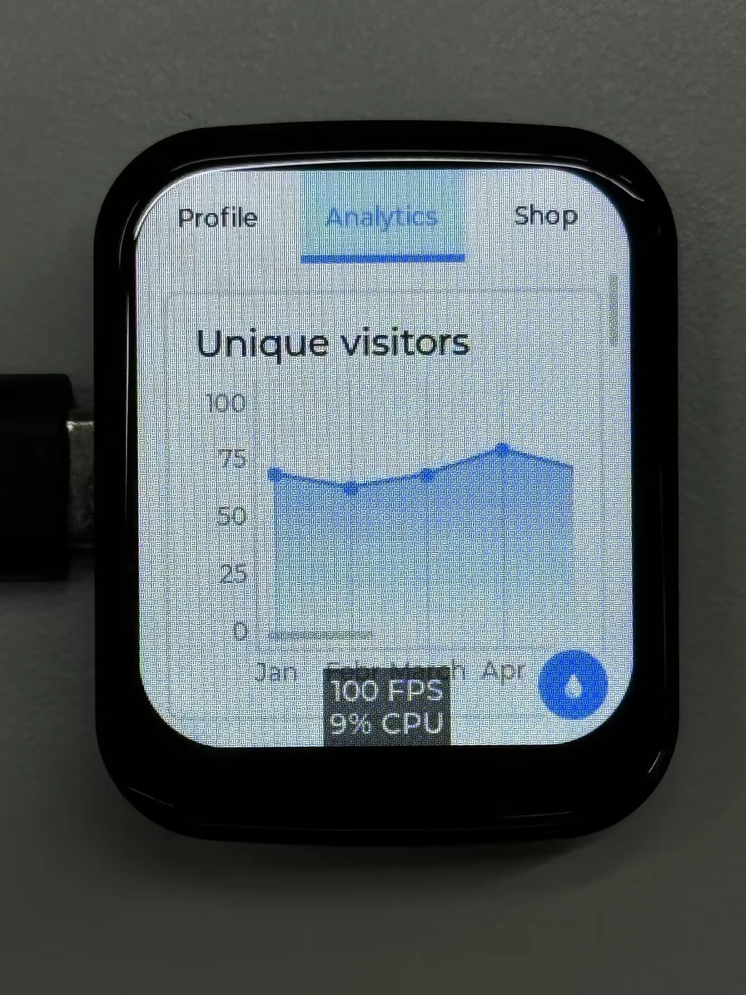
This example demonstrates the LVGL Widgets demo, achieving a frame rate of 20–30 FPS in dynamic states.
 |  |
|---|