Working with ESP-IDF
This chapter includes the following sections, please read as needed:
ESP-IDF Getting Started
New to ESP32 ESP-IDF development and looking to get started quickly? We have prepared a general Getting Started Tutorial for you.
- Section 1: Environment Setup
- Section 2: Running Examples
- Section 3: Creating a Project
- Section 4: Using Components
- Section 5: Debugging
- Section 6: FreeRTOS
- Section 7: Peripherals
- Section 8: Wi-Fi Programming
- Section 9: BLE Programming
Please Note: This tutorial uses the ESP32-S3-Zero as a teaching example, and all hardware code is based on its pinout. Before you start, it is recommended that you check the pinout of your development board to ensure the pin configuration is correct.
Setting Up Development Environment
For the ESP32-S3-Touch-LCD-1.69 development board, ESP-IDF V5.3.1 and above is required.
The following guide uses Windows as an example, demonstrating development using VS Code + the ESP-IDF extension. macOS and Linux users should refer to the official documentation.
The screenshots in this section use ESP-IDF V5.5.2 as an example. When installing, please select the ESP-IDF version that matches your board's example.
Install the ESP-IDF Development Environment
-
Download the installation manager from the ESP-IDF Installation Manager page. This is Espressif's latest cross-platform installer. The following steps demonstrate how to use its offline installation feature.
Click the Offline Installer tab on the page, then select Windows as the operating system and the ESP-IDF version you need (the version shown in the screenshot is for reference only — choose the version that fits your actual needs).

After confirming your selection, click the download button. The browser will automatically download two files: the ESP-IDF Offline Package (.zst) and the ESP-IDF Installer (.exe).

Please wait for both files to finish downloading.
-
Once the download is complete, double-click to run the ESP-IDF Installer (eim-gui-windows-x64.exe).
The installer will automatically detect if the offline package exists in the same directory. Click Install from archive.

Next, select the installation path. We recommend using the default path. If you need to customize it, ensure the path does not contain Chinese characters or spaces. Click Start installation to proceed.

-
When you see the following screen, the ESP-IDF installation is successful.

-
We recommend installing the drivers as well. Click Finish installation, then select Install driver.

Install Visual Studio Code and the ESP-IDF Extension
-
Download and install Visual Studio Code.
-
During installation, it is recommended to check Add "Open with Code" action to Windows Explorer file context menu to facilitate opening project folders quickly.
-
In VS Code, click the Extensions icon
 in the Activity Bar on the side (or use the shortcut Ctrl + Shift + X) to open the Extensions view.
 -
Enter ESP-IDF in the search box, locate the ESP-IDF extension, and click Install.

-
For ESP-IDF extension versions ≥ 2.0, the extension will automatically detect and recognize the ESP-IDF environment installed in the previous steps, requiring no manual configuration.
Example
The ESP-IDF examples are located in the ESP-IDF directory of the example package.
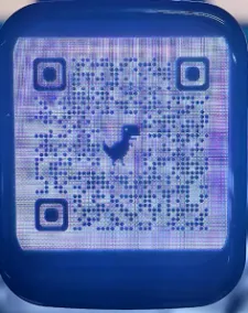
01_ESP_IDF_ST7789
This example demonstrates how to use the ST7789 display driver to perform various graphics and image tests on the ESP32-S3-Touch-LCD-1.69 development board. The program loads fonts and images via the SPIFFS file system and performs screen filling, color stripes, shape drawing, and BMP, JPEG, PNG image display.
 |  |  |  |  |
|---|
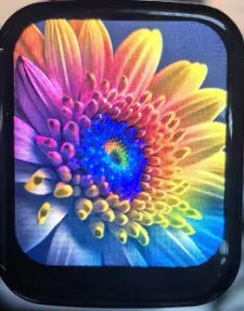
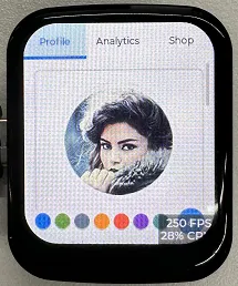
02_ESP_IDF_ST7789_LVGL
This example demonstrates the LVGL Widgets example.
 |  |
|---|
Code Analysis
app_lcd_init():
Configures and initializes the LCD backlight pin;
Initializes the SPI bus for communication with the LCD;
Creates the LCD panel I/O object and configures SPI-related parameters;
Installs the LCD driver, creates the LCD panel object, and performs initialization operations such as reset, enabling display, setting mirroring, etc.;
Turn on the LCD backlight.
app_lcd_init():
Initializes LVGL and configures parameters such as task priority, stack size, and timer period;
Configure the parameters of the LCD display and add it to the LVGL as a display device. In this way, LVGL can draw a graphical interface on this display.
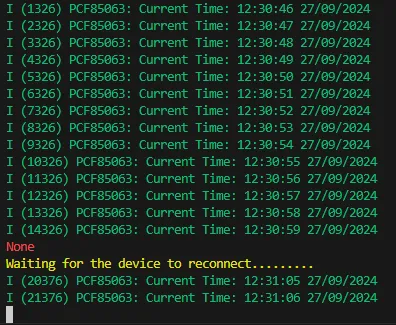
03_PCF85063
This example demonstrates how to use the onboard PCF85063 real-time clock (RTC) on the ESP32-S3-Touch-LCD-1.69 development board. The code initializes I2C communication with the RTC, sets the SCL and SDA pins, and defines the I2C communication frequency and timeout. Through implemented read/write register functions, it can get and set time information, aided by BCD data conversion functions. The application sets the RTC to a predetermined time and then continuously reads and outputs the current time every second in a FreeRTOS task loop, ensuring time information is continuously updated and displayed.
Code Analysis
rtc_get_time():
This function reads the current time from the RTC (real-time clock chip, here it is assumed to be PCF85063). It does so by calling rtc_read_reg to read 7 bytes of data from specific register addresses, representing seconds, minutes, hours, day, weekday, month, and year.
It converts the read BCD format data to decimal format and prints out the current time. If the read operation fails, an error message is printed and an error code is returned.
rtc_set_time():
This function sets the time of the RTC. It accepts hours, minutes, seconds, day, month, and year as parameters, converts these decimal values to BCD format, and assembles them into an array.
It then writes this array to the RTC starting at a specific register address by calling rtc_write_reg. If the write is successful, ESP_OK is returned; otherwise, the corresponding error code is returned.
04_QMI8658
This example demonstrates how to use the onboard QMI8658 sensor on the ESP32-S3-Touch-LCD-1.69 development board. The code initializes the sensor via I2C and configures the accelerometer and gyroscope parameters. A FreeRTOS task then continuously reads sensor data and outputs acceleration, angular velocity, timestamp, and temperature information.
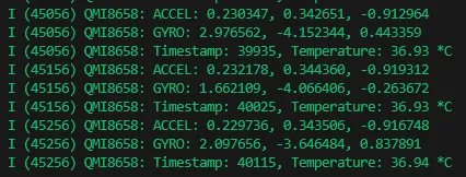
Code Analysis
read_sensor_data():- Uses
qmi.getAccelerometerto read accelerometer data. If successful, prints the three axes of accelerometer data. If it fails, prints an error message. - Uses
qmi.getGyroscopeto read gyroscope data. If successful, prints the three axes of gyroscope data. If it fails, prints an error message. - Uses
qmi.getTimestampandqmi.getTemperature_Cto obtain the sensor timestamp and temperature, respectively, and prints them. - If no data is ready, prints a warning message. Then waits for a short period before checking again for data readiness.
- Uses