FAQ
Q: How to get more library support for the examples?
A: You can subscribe to this repository and raise an issue to describe your requirements. The engineers will assess your request as soon as possible: ESP32-display-support
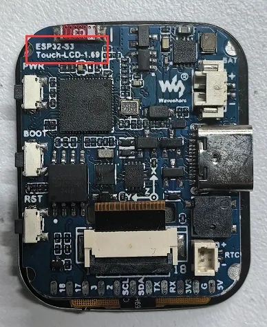
Q: Which version is my ESP32-S3-Touch-LCD-1.69 development board?
A: After receiving the product, if the board has the model printed on it, it is the new version; otherwise it is the old version. The pin definitions of the old and new versions differ slightly.
| Peripheral | Old Version | New Version |
|---|---|---|
| Buzzer (Buzz) | GPIO33 | GPIO42 |
| RTC interrupt (RTC_INT) | GPIO41 | GPIO39 |
| Power control (SYS_EN) | GPIO35 | GPIO41 |
| Power output (SYS_OUT) | GPIO36 | GPIO40 |
Q: The board is getting too hot. What is the reason and how do I fix it? How to solve it?
- If you find the board getting hot, first ensure the buzzer enable pin is pulled low. Otherwise, the passive buzzer will continuously consume power, putting a high current load on the LDO and causing it to overheat
- If you are also using Wi-Fi/Bluetooth features, overheating cannot be avoided. Enabling the wireless function on the ESP32-S3 will increase the power consumption, leading to overheating
- In the Arduino IDE environment, enabling PSRAM, using external Flash, and pulling the buzzer enable pin low can still generate significant heat. It is recommended to use low-power solutions
Q: Why does the flashing fail?
- When the serial port is occupied, the flashing will fail. Close the serial port monitor and try to flash again.
- When the ESP32 program crashes, the flashing will fail. In this case, you need to completely power off the development module, hold down BOOT button and power it on again to enter the forced download mode and then flash it. After flashing, the module will not automatically exit download mode, so you need to power cycle again.
Q: How can I check which COM port I am using?
Windows System:
- Through Device Manager: Press the Windows + R keys to open the "Run" dialog box; input devmgmt.msc and press Enter to open the Device Manager; expand the "Ports (COM and LPT)" section, where all COM ports and their current statuses will be listed.
- Using Command Prompt: Open the Command Prompt (CMD), enter the mode command, which will display status information for all COM ports.
- Check the hardware connection: If an external device is already connected to a COM port, the device typically occupies a port number. You can determine which port is being used by checking the connected hardware.
Linux System:
- Use the
dmesgcommand: Open the terminal. - Use the
lscommand: Typels /dev/ttyS*orls /dev/ttyUSB*to list all serial devices. - Use the
setserialcommand: Typesetserial -g /dev/ttyS*to view configuration information for all serial devices.
Q: How to port the provided lib libraries? Or how to develop my own LCD screen? How to drive it?
The LCD screen display chip used in this product is ST7789V2, and the touch chip is CST816T (for touch version only). There are two chip drivers in the lib we provide. For display drivers, please refer to GFX enable. For touch drivers, please refer to Arduino_LVGL example.
Q: Can you help me review or modify my code? Can you help me modify the code?
This product is positioned as a development board, not a finished product. This product is positioned as a development board, not a finished product. The product ecosystem is based on the ESP32 core, which is very mature and the development environment is very friendly. We do not assist in modifying code. Please let the makers and geeks use their DIY skills. If you have questions, you can ask our engineers for answers.
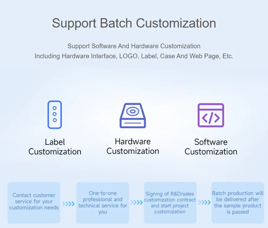
If you like our product and wish to customize hardware, casing, software, etc. in bulk, please feel free to contact our sales.
Q: What is the exact spacing between the 11 test points on the back of the ESP32-S3-Touch-LCD-1.69?
2.15mm
Q: Why is there no output even though the code is correct and flashed successfully?
- Check the schematic diagram: Depending on the Type-C interface of your specific development board, the code handling the output differs:
- For boards with a direct USB connection, they support output via the printf function. To support output via the Serial function, you need to enable the USB CDC On Boot feature or declare HWCDC
- For boards with a UART-to-USB connection, they support output via both printf and Serial functions, and there is no need to enable USB CDC On Boot
Q: How to use SquareLine Studio to design interfaces?
Please refer to SquareLine Studio Tutorial.
Q: What is the radius of the rounded corners marked in green on the screen and the circuit board?
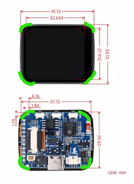
- The screen corner radius is 5mm; the board radius is 5.1mm (essentially the same). The slight difference is due to positioning holes.