Working with Arduino
This chapter contains the following sections. Please read as needed:
Arduino Getting Started
New to Arduino ESP32 development and looking for a quick start? We have prepared a comprehensive Getting Started Tutorial for you.
- Section 0: Getting to Know ESP32
- Section 1: Installing and Configuring Arduino IDE
- Section 2: Arduino Basics
- Section 3: Digital Output/Input
- Section 4: Analog Input
- Section 5: Pulse Width Modulation (PWM)
- Section 6: Serial Communication (UART)
- Section 7: I2C Communication
- Section 8: SPI Communication
- Section 9: Wi-Fi Basics
- Section 10: Web Server
- Section 11: Bluetooth
- Section 12: LVGL GUI Development
- Section 13: Comprehensive Project
Note: This tutorial uses the ESP32-S3-Zero as a reference example, and all hardware code is based on its pinout. Before you start, we recommend checking the pinout of your development board to ensure the pin configuration is correct.
Setting Up Development Environment
1. Installing and Configuring Arduino IDE
Please refer to the tutorial Installing and Configuring Arduino IDE to download and install the Arduino IDE and add ESP32 support.
| Board Name | Board Installation Requirement | Version Requirement |
|---|---|---|
| esp32 by Espressif Systems | "Install Offline" / "Install Online" | 3.0.5 |
2. Installing Libraries
To run the example, you need to install the corresponding library. The example code uses the GFX Library for Arduino library to drive the ST7789V2 display
and the Arduino_DriveBus library to drive the CST816T touch controller.
You can click this link to download the example package for the ESP32-S3-Touch-LCD-1.83 development board. The Arduino\libraries directory within this package contains all the necessary library files required for this tutorial.
| Library/File Name | Description | Version | Installation Method |
|---|---|---|---|
| Arduino_DriveBus | CST816 touch controller driver library | v1.0.1 | "Install Offline" |
| GFX Library for Arduino | ST7789 display driver graphics library | v1.4.9 | "Install Online" or "Install Offline" |
| SensorLib | PCF85063, QMI8658 sensor driver library | v0.1.6 | "Install Online" or "Install Offline" |
| lvgl | LVGL graphical library | v8.4.0 | "Install Online" requires copying the demos folder to src after installation. "Install Offline" is recommended |
| Mylibrary | Development board pin macro definitions | -- | "Install Offline" |
| lv_conf.h | LVGL configuration file | -- | "Install Offline" |
There are strong dependencies between versions of LVGL and its driver libraries. For example, a driver written for LVGL v8 may not be compatible with LVGL v9. To ensure that the examples can be reproduced reliably, it is recommended to use the specific versions listed in the table above. Mixing different versions of libraries may lead to compilation failures or runtime errors.
Installation Steps:
-
Unzip the downloaded example package.
-
Copy all folders (Arduino_DriveBus, GFX_Library_for_Arduino, etc.) in the
Arduino\librariesdirectory to the Arduino library folder.infoThe path to the Arduino libraries folder is typically:
c:\Users\<username>\Documents\Arduino\libraries.You can also locate it in the Arduino IDE by going to File > Preferences and checking the "Sketchbook location". The libraries folder is the
librariessubfolder within this path. -
For other installation methods, please refer to: Arduino Library Management Tutorial.
3. Other Tips
-
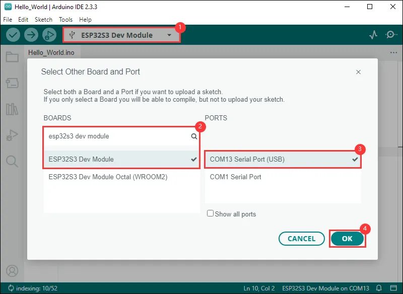
The ESP32-S3-Touch-LCD-1.83 can be directly selected in the Arduino IDE.
-
The ESP32-S3-Touch-LCD-1.83 uses the ESP32-S3 native USB interface, not UART-to-USB. For serial communication:
-
The
printf()function can be used directly; -
To use the
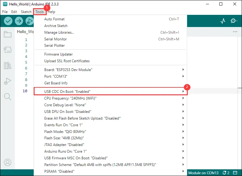
Serial.println()function, additional configuration is required: Enable the "USB CDC On Boot" option in the IDE's Tools menu, or declare anHWCDCobject in your code to handle USB serial communication.noteAs shown in the figure, set "USB CDC On Boot" in the "Tools" option of the Arduino IDE
-
Example
The Arduino examples are located in the Arduino/examples directory of the example package.
| Example | Basic Description | Dependency Library |
|---|---|---|
| 01_HelloWorld | Demonstrates basic graphics library functions, can also be used to test the basic performance of the display and random text display effects | GFX_Library_for_Arduino |
| 02_Drawing_board | Demonstrates basic graphics library functions, can also be used to test the basic performance of the display and random text display effects | GFX_Library_for_Arduino, Arduino DriveBus |
| 03_GFX_AsciiTable | Prints ASCII characters in rows and columns on the screen according to the screen size | GFX_Library_for_Arduino |
| 04_GFX_ESPWiFiAnalyzer | Draws Wi-Fi band signal strength on the ST7789 display | GFX_Library_for_Arduino |
| 05_GFX_Clock | A simple ST7789 clock example implementing a clock with simple tick marks and time management | GFX_Library_for_Arduino |
| 06_GFX_PCF85063_simpleTime | Displays the current time | SensorLib, GFX_Library_for_Arduino |
| 07_LVGL_PCF85063_simpleTime | Displays current time on the ST7789 display using the PCF85063 RTC module under LVGL | LVGL, SensorLib |
| 08_LVGL_QMI8658_ui | Uses LVGL for graphical display and communicates with the QMI8658 IMU to obtain accelerometer and gyroscope data | LVGL, SensorLib |
| 09_LVGL_Arduino | LVGL demo | LVGL, Arduino DriveBus |
01_HelloWorld
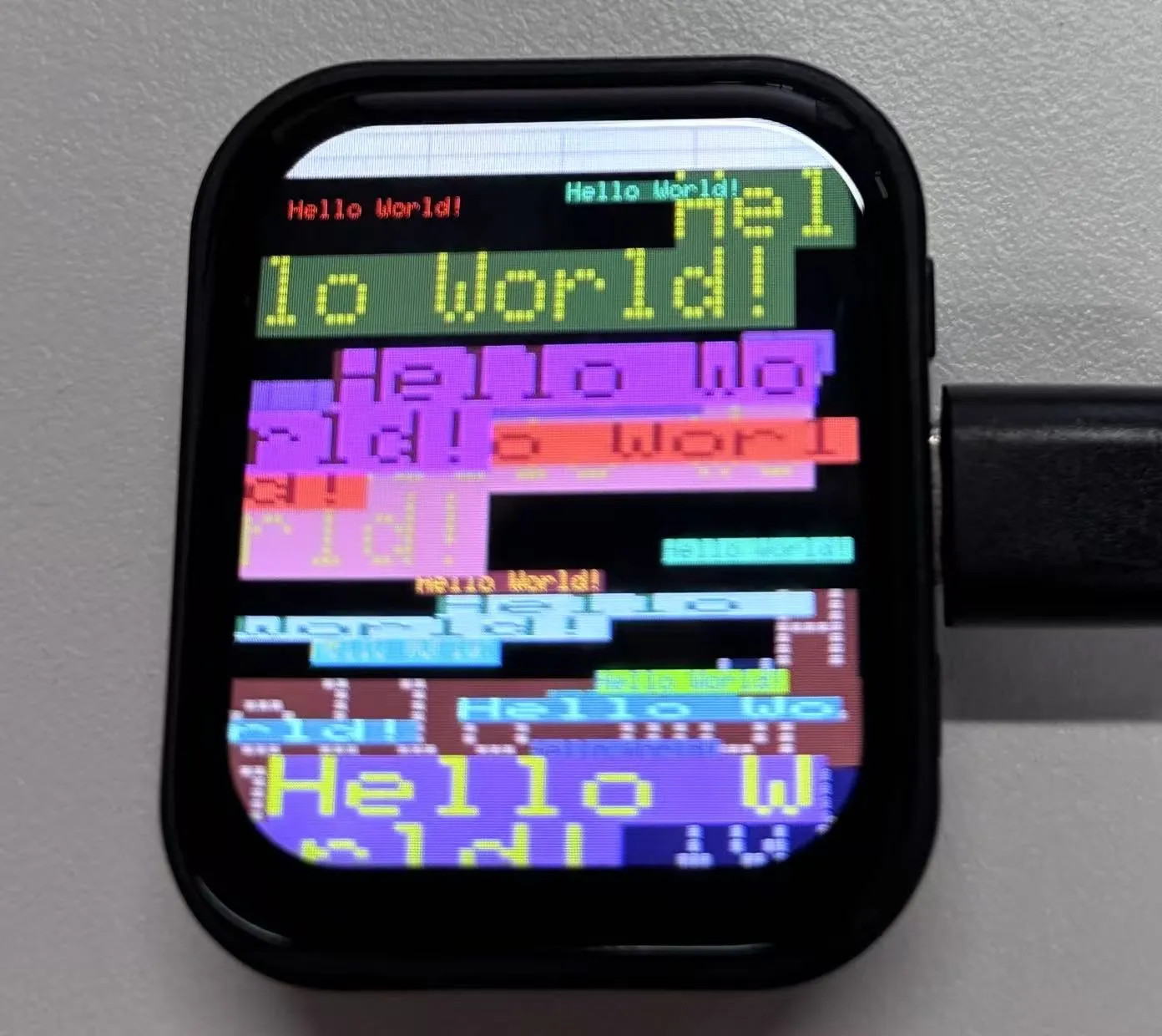
This example demonstrates how to use the Arduino GFX library and the Arduino DriveBus library to control the ST7789 display, showing basic graphics library functions through dynamically changing text. This code can also be used to test the basic performance of the display and the effect of displaying random text.
Hardware Connection
- Connect the board to the computer using a USB cable
Code Analysis
-
Display initialization:
if (!gfx->begin()) {USBSerial.println("gfx->begin() failed!");} -
Clear the screen and display text:
gfx->fillScreen(BLACK);gfx->setCursor(10, 10);gfx->setTextColor(RED);gfx->println("Hello World!"); -
Animated display:
gfx->setCursor(random(gfx->width()), random(gfx->height()));gfx->setTextColor(random(0xffff), random(0xffff));gfx->setTextSize(random(6), random(6), random(2));gfx->println("Hello World!");
Operation Result
- This example demonstrates how to use the Arduino GFX library and the Arduino DriveBus library to control the ST7789 display, showing basic graphics library functions through dynamically changing text. This code can also be used to test the basic performance of the display and the effect of displaying random text.
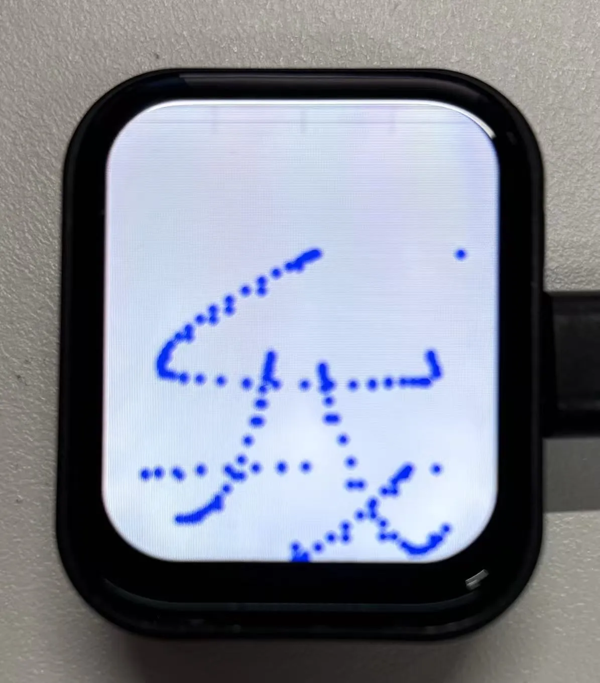
02_Drawing_board
- This example demonstrates how to use the ESP32 to control the CST816 touch controller and TCA9554 GPIO expander via I2C, while using the Arduino GFX library to drive the ST7789 display.
Hardware Connection
- Connect the board to the computer using a USB cable
Code Analysis
-
Display initialization and brightness fade animation:
gfx->begin();gfx->fillScreen(WHITE);for(int i = 0;i <= 255;i++){gfx->Display_Brightness(i);gfx->setCursor(30, 150);gfx->setTextColor(BLUE);gfx->setTextSize(4);gfx->println("Loading board");delay(3);}
Operation Result
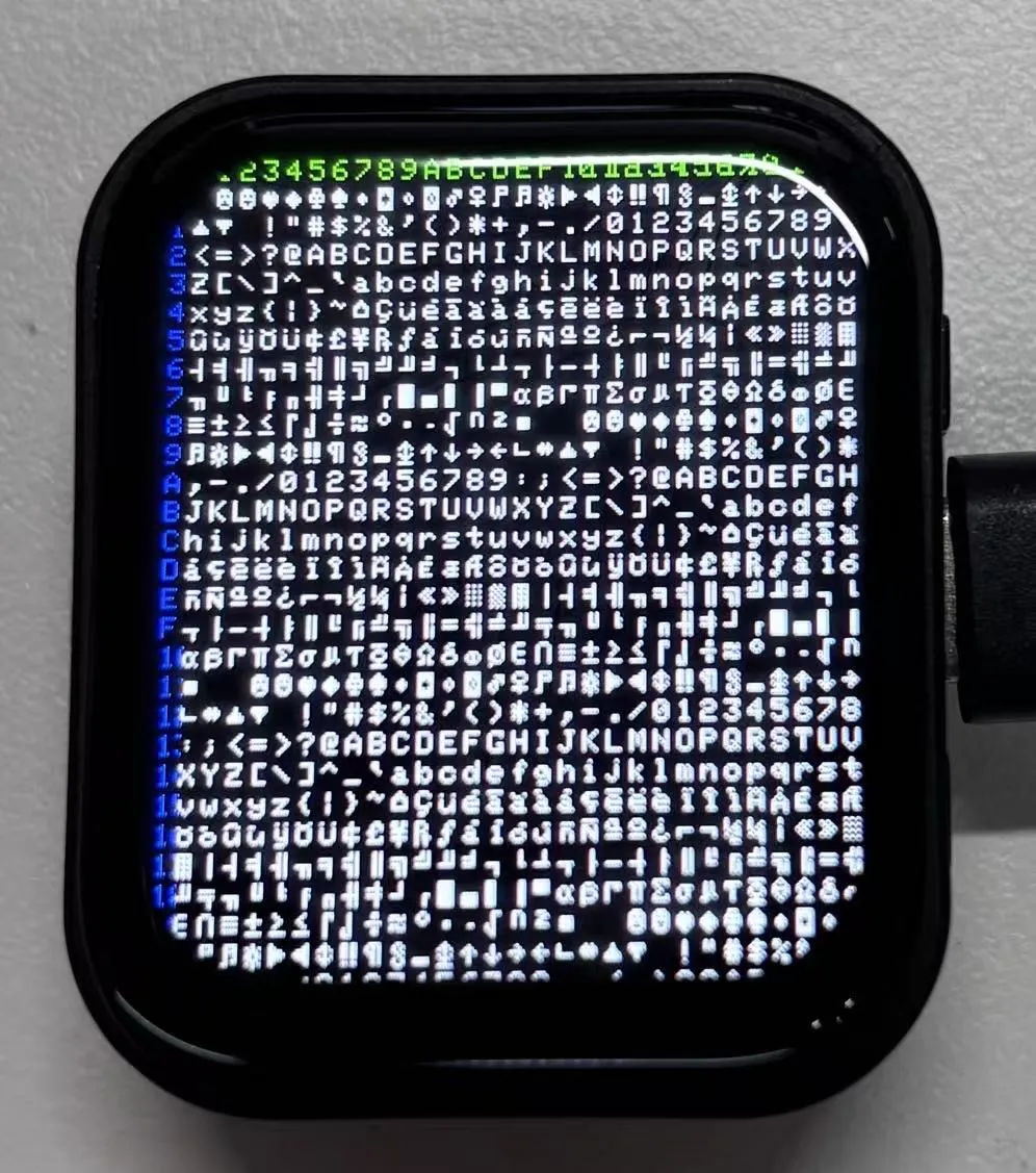
03_GFX_AsciiTable
This example shows how to create an ASCII table display effect using the ST7789 display and the Arduino GFX library. Specifically, after initializing the display, the code displays ASCII character indices on the screen according to predefined colors and positions. First, the string "Arduino_GFX AsciiTable example" is printed to the serial monitor via USBSerial. Then indices are displayed in two colors (green and blue) at fixed positions, followed by the full ASCII character table displayed in white on a black background.
Hardware Connection
- Connect the board to the computer using a USB cable
Code Analysis
-
Initialize the display:
if (!gfx->begin()) {USBSerial.println("gfx->begin() failed!");} -
Calculate rows and columns and label them:
Based on the display dimensions, it calculates the number of columns and rows that can be displayed. Then, using two loops with different text colors, it prints row and column numbers on the display, making it easy to determine character positions when drawing the ASCII table later.
int numCols = LCD_WIDTH / 8;int numRows = LCD_HEIGHT / 10;// Label the line numbergfx->setTextColor(GREEN);for (int x = 0; x < numRows; x++) {gfx->setCursor(10 + x * 8, 2);gfx->print(x, 16);}// Label the column numbergfx->setTextColor(BLUE);for (int y = 0; y < numCols; y++) {gfx->setCursor(2, 12 + y * 10);gfx->print(y, 16);} -
Draws the ASCII character table:
char c = 0;for (int y = 0; y < numRows; y++) {for (int x = 0; x < numCols; x++) {gfx->drawChar(10 + x * 8, 12 + y * 10, c++, WHITE, BLACK);}}
Operation Result
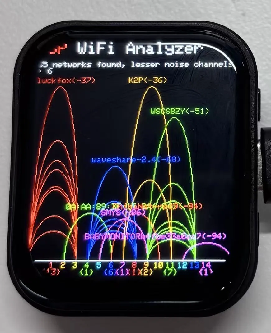
04_GFX_ESPWiFiAnalyzer
This example demonstrates drawing Wi-Fi band signal strength on the ST7789 display, implementing the functionality of a Wi-Fi analyzer.
Hardware Connection
- Connect the board to the computer using a USB cable
Code Analysis
-
setup():- Initializes serial communication;
- Sets Wi-Fi to station mode and disconnects;
- Initializes the display, gets screen dimensions and calculates various drawing parameters;
- Sets the screen background to black and draws the title bar.
-
loop():- Scans Wi-Fi networks and retrieves network information, including channel, RSSI, BSSID, and SSID;
- Counts the number of networks per channel, noise levels, and peak signal strengths;
- Clears the old graph and draws a new one based on the scan results, including signal strength ellipses and network information text;
- Prints the number of networks found and the channels with the least noise;
- Draws the graph baseline and channel numbers;
- Enters low-power mode based on conditions.
Operation Result
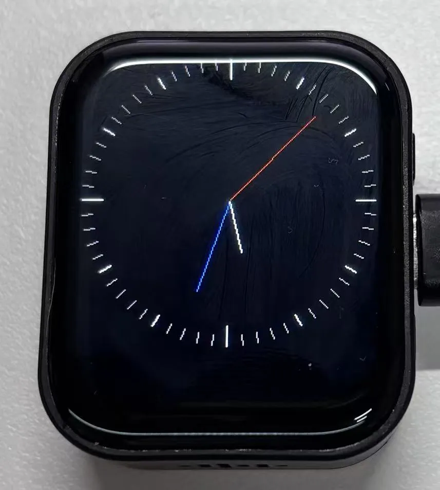
05_GFX_Clock
This example demonstrates a simple ST7789 clock example, implementing a clock with simple tick marks and time management.
Hardware Connection
- Connect the board to the computer using a USB cable
05_GFX_Clock.ino
#include <Arduino.h>
#include "Arduino_GFX_Library.h"
#include "pin_config.h"
#include <Wire.h>
#include "HWCDC.h"
HWCDC USBSerial;
// SensorPCF85063 rtc;
Arduino_DataBus *bus = new Arduino_ESP32SPI(LCD_DC, LCD_CS, LCD_SCK, LCD_MOSI);
Arduino_GFX *gfx = new Arduino_ST7789(bus, LCD_RST /* RST */,
0 /* rotation */, true /* IPS */, LCD_WIDTH, LCD_HEIGHT, 0, 20, 0, 0);
#define BACKGROUND BLACK
#define MARK_COLOR WHITE
#define SUBMARK_COLOR DARKGREY // LIGHTGREY
#define HOUR_COLOR WHITE
#define MINUTE_COLOR BLUE // LIGHTGREY
#define SECOND_COLOR RED
#define SIXTIETH 0.016666667
#define TWELFTH 0.08333333
#define SIXTIETH_RADIAN 0.10471976
#define TWELFTH_RADIAN 0.52359878
#define RIGHT_ANGLE_RADIAN 1.5707963
static uint8_t conv2d(const char *p)
{
uint8_t v = 0;
return (10 * (*p - '0')) + (*++p - '0');
}
static int16_t w, h, center;
static int16_t hHandLen, mHandLen, sHandLen, markLen;
static float sdeg, mdeg, hdeg;
static int16_t osx = 0, osy = 0, omx = 0, omy = 0, ohx = 0, ohy = 0; // Saved H, M, S x & y coords
static int16_t nsx, nsy, nmx, nmy, nhx, nhy; // H, M, S x & y coords
static int16_t xMin, yMin, xMax, yMax; // redraw range
static int16_t hh, mm, ss;
static unsigned long targetTime; // next action time
static int16_t *cached_points;
static uint16_t cached_points_idx = 0;
static int16_t *last_cached_point;
void setup(void)
{
USBSerial.begin(115200);
USBSerial.println("Arduino_GFX Clock example");
// Init Display
if (!gfx->begin()) {
   USBSerial.println("gfx->begin() failed!");
 }
gfx->fillScreen(BACKGROUND);
pinMode(LCD_BL, OUTPUT);
digitalWrite(LCD_BL, HIGH);
// init LCD constant
w = gfx->width();
h = gfx->height();
if (w < h)
{
center = w / 2;
}
else
{
center = h / 2;
}
hHandLen = center * 3 / 8;
mHandLen = center * 2 / 3;
sHandLen = center * 5 / 6;
markLen = sHandLen / 6;
cached_points = (int16_t *)malloc((hHandLen + 1 + mHandLen + 1 + sHandLen + 1) * 2 * 2);
// Draw 60 clock marks
draw_round_clock_mark(
// draw_square_clock_mark(
center - markLen, center,
center - (markLen * 2 / 3), center,
center - (markLen / 2), center);
hh = conv2d(__TIME__);
mm = conv2d(__TIME__ + 3);
ss = conv2d(__TIME__ + 6);
targetTime = ((millis() / 1000) + 1) * 1000;
}
void loop()
{
unsigned long cur_millis = millis();
if (cur_millis >= targetTime)
{
targetTime += 1000;
ss++; // Advance second
if (ss == 60)
{
ss = 0;
mm++; // Advance minute
if (mm > 59)
{
mm = 0;
hh++; // Advance hour
if (hh > 23)
{
hh = 0;
}
}
}
}
// Pre-compute hand degrees, x & y coords for a fast screen update
sdeg = SIXTIETH_RADIAN * ((0.001 * (cur_millis % 1000)) + ss); // 0-59 (includes millis)
nsx = cos(sdeg - RIGHT_ANGLE_RADIAN) * sHandLen + center;
nsy = sin(sdeg - RIGHT_ANGLE_RADIAN) * sHandLen + center;
if ((nsx != osx) || (nsy != osy))
{
mdeg = (SIXTIETH * sdeg) + (SIXTIETH_RADIAN * mm); // 0-59 (includes seconds)
hdeg = (TWELFTH * mdeg) + (TWELFTH_RADIAN * hh); // 0-11 (includes minutes)
mdeg -= RIGHT_ANGLE_RADIAN;
hdeg -= RIGHT_ANGLE_RADIAN;
nmx = cos(mdeg) * mHandLen + center;
nmy = sin(mdeg) * mHandLen + center;
nhx = cos(hdeg) * hHandLen + center;
nhy = sin(hdeg) * hHandLen + center;
// redraw hands
redraw_hands_cached_draw_and_erase();
ohx = nhx;
ohy = nhy;
omx = nmx;
omy = nmy;
osx = nsx;
osy = nsy;
delay(1);
}
}
void draw_round_clock_mark(int16_t innerR1, int16_t outerR1, int16_t innerR2, int16_t outerR2, int16_t innerR3, int16_t outerR3)
{
float x, y;
int16_t x0, x1, y0, y1, innerR, outerR;
uint16_t c;
for (uint8_t i = 0; i < 60; i++)
{
if ((i % 15) == 0)
{
innerR = innerR1;
outerR = outerR1;
c = MARK_COLOR;
}
else if ((i % 5) == 0)
{
innerR = innerR2;
outerR = outerR2;
c = MARK_COLOR;
}
else
{
innerR = innerR3;
outerR = outerR3;
c = SUBMARK_COLOR;
}
mdeg = (SIXTIETH_RADIAN * i) - RIGHT_ANGLE_RADIAN;
x = cos(mdeg);
y = sin(mdeg);
x0 = x * outerR + center;
y0 = y * outerR + center;
x1 = x * innerR + center;
y1 = y * innerR + center;
gfx->drawLine(x0, y0, x1, y1, c);
}
}
void draw_square_clock_mark(int16_t innerR1, int16_t outerR1, int16_t innerR2, int16_t outerR2, int16_t innerR3, int16_t outerR3)
{
float x, y;
int16_t x0, x1, y0, y1, innerR, outerR;
uint16_t c;
for (uint8_t i = 0; i < 60; i++)
{
if ((i % 15) == 0)
{
innerR = innerR1;
outerR = outerR1;
c = MARK_COLOR;
}
else if ((i % 5) == 0)
{
innerR = innerR2;
outerR = outerR2;
c = MARK_COLOR;
}
else
{
innerR = innerR3;
outerR = outerR3;
c = SUBMARK_COLOR;
}
if ((i >= 53) || (i < 8))
{
x = tan(SIXTIETH_RADIAN * i);
x0 = center + (x * outerR);
y0 = center + (1 - outerR);
x1 = center + (x * innerR);
y1 = center + (1 - innerR);
}
else if (i < 23)
{
y = tan((SIXTIETH_RADIAN * i) - RIGHT_ANGLE_RADIAN);
x0 = center + (outerR);
y0 = center + (y * outerR);
x1 = center + (innerR);
y1 = center + (y * innerR);
}
else if (i < 38)
{
x = tan(SIXTIETH_RADIAN * i);
x0 = center - (x * outerR);
y0 = center + (outerR);
x1 = center - (x * innerR);
y1 = center + (innerR);
}
else if (i < 53)
{
y = tan((SIXTIETH_RADIAN * i) - RIGHT_ANGLE_RADIAN);
x0 = center + (1 - outerR);
y0 = center - (y * outerR);
x1 = center + (1 - innerR);
y1 = center - (y * innerR);
}
gfx->drawLine(x0, y0, x1, y1, c);
}
}
void redraw_hands_cached_draw_and_erase() {
    gfx->startWrite();
    draw_and_erase_cached_line(center, center, nsx, nsy, SECOND_COLOR, cached_points, sHandLen + 1, false, false);
    draw_and_erase_cached_line(center, center, nhx, nhy, HOUR_COLOR, cached_points + ((sHandLen + 1) * 2), hHandLen + 1, true, false);
    draw_and_erase_cached_line(center, center, nmx, nmy, MINUTE_COLOR, cached_points + ((sHandLen + 1 + hHandLen + 1) * 2), mHandLen + 1, true, true);
    gfx->endWrite();
}
void draw_and_erase_cached_line(int16_t x0, int16_t y0, int16_t x1, int16_t y1, int16_t color, int16_t *cache, int16_t cache_len, bool cross_check_second, bool cross_check_hour)
{
#if defined(ESP8266)
yield();
#endif
bool steep = _diff(y1, y0) > _diff(x1, x0);
if (steep)
{
_swap_int16_t(x0, y0);
_swap_int16_t(x1, y1);
}
int16_t dx, dy;
dx = _diff(x1, x0);
dy = _diff(y1, y0);
int16_t err = dx / 2;
int8_t xstep = (x0 < x1) ? 1 : -1;
int8_t ystep = (y0 < y1) ? 1 : -1;
x1 += xstep;
int16_t x, y, ox, oy;
for (uint16_t i = 0; i <= dx; i++)
{
if (steep)
{
x = y0;
y = x0;
}
else
{
x = x0;
y = y0;
}
ox = *(cache + (i * 2));
oy = *(cache + (i * 2) + 1);
if ((x == ox) && (y == oy))
{
if (cross_check_second || cross_check_hour)
{
write_cache_pixel(x, y, color, cross_check_second, cross_check_hour);
}
}
else
{
write_cache_pixel(x, y, color, cross_check_second, cross_check_hour);
if ((ox > 0) || (oy > 0))
{
write_cache_pixel(ox, oy, BACKGROUND, cross_check_second, cross_check_hour);
}
*(cache + (i * 2)) = x;
*(cache + (i * 2) + 1) = y;
}
if (err < dy)
{
y0 += ystep;
err += dx;
}
err -= dy;
x0 += xstep;
}
for (uint16_t i = dx + 1; i < cache_len; i++)
{
ox = *(cache + (i * 2));
oy = *(cache + (i * 2) + 1);
if ((ox > 0) || (oy > 0))
{
write_cache_pixel(ox, oy, BACKGROUND, cross_check_second, cross_check_hour);
}
*(cache + (i * 2)) = 0;
*(cache + (i * 2) + 1) = 0;
}
}
void write_cache_pixel(int16_t x, int16_t y, int16_t color, bool cross_check_second, bool cross_check_hour)
{
int16_t *cache = cached_points;
if (cross_check_second)
{
for (uint16_t i = 0; i <= sHandLen; i++)
{
if ((x == *(cache++)) && (y == *(cache)))
{
return;
}
cache++;
}
}
if (cross_check_hour)
{
cache = cached_points + ((sHandLen + 1) * 2);
for (uint16_t i = 0; i <= hHandLen; i++)
{
if ((x == *(cache++)) && (y == *(cache)))
{
return;
}
cache++;
}
}
gfx->writePixel(x, y, color);
}
Code Analysis
-
Drawing hour, minute, and second hands:
void redraw_hands_cached_draw_and_erase() {gfx->startWrite();draw_and_erase_cached_line(center, center, nsx, nsy, SECOND_COLOR, cached_points, sHandLen + 1, false, false);draw_and_erase_cached_line(center, center, nhx, nhy, HOUR_COLOR, cached_points + ((sHandLen + 1) * 2), hHandLen + 1, true, false);draw_and_erase_cached_line(center, center, nmx, nmy, MINUTE_COLOR, cached_points + ((sHandLen + 1 + hHandLen + 1) * 2), mHandLen + 1, true, true);gfx->endWrite();}
Operation Result
06_GFX_PCF85063_simpleTime
This example demonstrates using the PCF85063 RTC module to display the current time on the ST7789 display. It retrieves the time every second and updates the display only when the time changes.
Hardware Connection
- Connect the board to the computer using a USB cable
Code Analysis
loop():- First, get the current time. If the current time is different from the previously displayed time, do the following:
- Clear the area where the previous time was displayed by filling a rectangle, so that overlapping does not occur when updating the time.
- Set the text color to black and the text size to 3.
- Call
getCenteredXto calculate the X coordinate for centering the current time string on the screen. - Set the cursor position and print the current time string, updating the time display.
- Copy the current time string to
previousTimeStringfor the next comparison.
Operation Result

07_LVGL_PCF85063_simpleTime
This example demonstrates using the PCF85063 RTC module under LVGL to display the current time on the ST7789 display. It retrieves the time every second and updates the display only when the time changes, providing a smoother time refresh effect.
Hardware Connection
- Connect the board to the computer using a USB cable
Code Analysis
-
setup():- Initializes serial communication at 115200 baud for possible serial debugging;
- Attempts to connect to the PCF85063 real-time clock chip; if it fails, enters an infinite loop;
- Sets the initial RTC time to 2025-10-23 15:23:49;
- Initializes the display and sets screen brightness;
- Initializes LVGL and registers a log output function (if logging is enabled);
- Configures the LVGL display driver and drawing buffer, and initializes a dummy input device driver;
- Creates a timer to periodically trigger LVGL tick updates;
- Creates a label and sets its initial text to "Initializing...".
-
loop(): -
Calls
lv_timer_handlerto let LVGL handle GUI tasks; -
Every second, checks whether the time has been updated; if so, retrieves the current time from the RTC, outputs it via serial, formats it as a string, updates the label's text, and sets the label's font to
lv_font_montserrat_40.
Operation Result

08_LVGL_QMI8658_ui
- This example demonstrates using LVGL for graphical display and communicating with the QMI8658 IMU to obtain accelerometer and gyroscope data.
Hardware Connection
- Connect the board to the computer using a USB cable
Code Analysis
-
my_disp_flush():- This function is the refresh funtion of LVGL display driver. It is responsible for refreshing the LVGL drawing buffer content to the display screen;
- Depending on the color format setting, it calls the appropriate
gfxobject function to draw the bitmap to the specified area. - Finally, it notifies LVGL that the display refreshing is complete.
-
loop():- Calls
lv_timer_handlerto let LVGL handle GUI tasks; - Checks whether new data is ready from the
qmi(QMI8658 sensor object). If so, attempts to retrieve accelerometer data and gyroscope data and outputs them via serial; - Simultaneously, updates the LVGL chart with the accelerometer data to display real-time changes in acceleration on the three axes;
- Uses
delay(20)to increase the data polling frequency, ensuring timely retrieval of sensor data and display updates.
- Calls
Operation Result

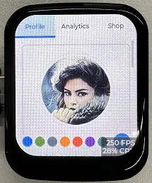
09_LVGL_Arduino
This example demonstrates the LVGL Widgets demo, achieving a frame rate of 20–30 FPS in dynamic states.
Hardware Connection
- Connect the board to the computer using a USB cable
Operation Result
-
This example demonstrates the LVGL Widgets example, achieving a frame rate of 20–30 FPS in dynamic states.
-
When developing with the LVGL framework, you can refer to the component documentation provided by the official LVGL documentation: LVGL8.3 Documents
-
Below is an actual LVGL component exploration case in the Arduino IDE:
