Working with Arduino
This chapter contains the following sections. Please read as needed:
Arduino Getting Started
New to Arduino ESP32 development and looking for a quick start? We have prepared a comprehensive Getting Started Tutorial for you.
- Section 0: Getting to Know ESP32
- Section 1: Installing and Configuring Arduino IDE
- Section 2: Arduino Basics
- Section 3: Digital Output/Input
- Section 4: Analog Input
- Section 5: Pulse Width Modulation (PWM)
- Section 6: Serial Communication (UART)
- Section 7: I2C Communication
- Section 8: SPI Communication
- Section 9: Wi-Fi Basics
- Section 10: Web Server
- Section 11: Bluetooth
- Section 12: LVGL GUI Development
- Section 13: Comprehensive Project
Note: This tutorial uses the ESP32-S3-Zero as a reference example, and all hardware code is based on its pinout. Before you start, we recommend checking the pinout of your development board to ensure the pin configuration is correct.
Setting Up Development Environment
Install and Configure Arduino IDE
Please refer to the tutorial Installing and Configuring Arduino IDE to download and install the Arduino IDE and add ESP32 support.
Version 1.0
| Board Name | Board Installation Requirement | Version Requirement |
|---|---|---|
| esp32 by Espressif Systems | "Install Offline" / "Install Online” | 3.0.2 ≤ Version ≤ 3.1.1 |
Install Libraries
- When installing Arduino libraries, there are typically two methods: Install Online and Install Offline. If the library installation requires Install Offline, you must use the provided library file.
- For most libraries, users can easily search for and install them via the Arduino IDE's online Library Manager. However, some open-source or custom libraries are not synchronized to the Arduino Library Manager and therefore cannot be found through online search. In this case, users can only install these libraries manually via offline methods.
- The sample program package for the ESP32-S3-Touch-LCD-1.85 development board can be downloaded from here. The
Arduino\librariesdirectory within the package already contains all the library files required for this tutorial.
| Library/File Name | Description | Version | Installation Method |
|---|---|---|---|
| LVGL | Graphics Library | v8.3.10 | "Install Offline” |
| ESP32-audioI2S-master | Audio Decoding Library | v2.0.0 | "Install Offline” |
Version 2.0
| Board Name | Installation Requirement | Version Requirement |
|---|---|---|
| esp32 by Espressif Systems | "Install Offline" / "Install Online” | 3.2.0 |
Install Libraries
- When installing Arduino libraries, there are typically two methods: Install Online and Install Offline. If the library installation requires Install Offline, you must use the provided library file.
- For most libraries, users can easily search for and install them via the Arduino IDE's online Library Manager. However, some open-source or custom libraries are not synchronized to the Arduino Library Manager and therefore cannot be found through online search. In this case, users can only install these libraries manually via offline methods.
- The sample program package for the ESP32-S3-Touch-LCD-1.85 development board can be downloaded from here. The
Arduino\librariesdirectory within the package already contains all the library files required for this tutorial.
| Library/File Name | Description | Version | Installation Method |
|---|---|---|---|
| LVGL | Graphics Library | v9.3.0 | "Install Offline” |
| ESP32-audioI2S-master | Audio Decoding Library | v2.0.0 | "Install Offline” |
| ES7210 | Audio Encoding Library | - | "Install Offline" |
| ES8311 | Audio Decoding Library | - | "Install Offline" |
There are strong dependencies between versions of LVGL and its driver libraries. For example, a driver written for LVGL v8 may not be compatible with LVGL v9. To ensure that the examples can be reproduced reliably, it is recommended to use the specific versions listed in the table above. Mixing different versions of libraries may lead to compilation failures or runtime errors.
Arduino Project Parameter Settings
- If the example being flashed contains a speech recognition model, select "ESP SR 16M (3MB APP/7MB SPIFFS/2.9MB MODEL)" for the Partition Scheme.
- If the example being flashed does not contain a speech recognition model, select "16M Flash (3MB APP/9.9MB FATFS)" or another appropriate scheme.

Example-v1
LVGL_Arduino
Example Description
- This demo demonstrates the functionality of various onboard devices. Page 1 displays parameters such as SD Card, Flash Size, Battery Voltage, etc., while Page 2 is the music playback interface. Additionally, this example includes voice recognition functionality.
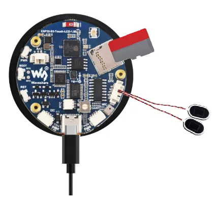
Hardware Connection
- Insert the TF card into the development board
- Connect the speaker to the development board
- Connect the development board to the computer
Code Analysis
setup(): Hardware initialization, configuring peripherals, etc.- Hardware Initialization:
setup()mainly executes several initialization functions to configure and initialize hardware components connected to the Arduino, such as RTC, gyroscope, LCD display, TF card, audio module, microphone, etc. Through these initializations, it ensures the hardware can function correctly. - GUI Initialization: Calls
Lvgl_Init()to initialize LVGL (Light and Versatile Graphics Library), a widely used graphics library for embedded systems.Lvgl_Example1()is an example program used to demonstrate how to render a graphical interface on the display. - Task Scheduling: The
Driver_Loop()function creates a task (DriverTask) for managing and cyclically executing operations for some peripherals.
- Hardware Initialization:
loop(): Mainly used for GUI updates and task scheduling.- LVGL Task Loop:
Lvgl_Loop()is a loop function of the LVGL library, used to handle GUI updates, event responses, and other UI-related operations. In embedded systems, graphics libraries typically need to be called frequently in the main loop to maintain screen refresh and real-time interactivity. - Task Scheduling Control:
vTaskDelay(pdMS_TO_TICKS(5))pauses the task for 5 milliseconds.vTaskDelayis a delay function in FreeRTOS, aiming to reduce CPU usage, avoid occupying too much time slice, and ensure other system tasks (such as peripheral processing) can execute on time.
- LVGL Task Loop:
Operation Result
-
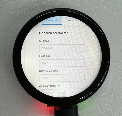
LCD Screen Display
-
LCD Screen Display Parameter Description
Parameter Function Description SD Card Displays the TF card size Connect a TF card. If recognition fails, please format the TF card to FAT32 (if initial recognition fails, wait a moment and then reset to check again) Flash Size Displays the Flash size Onboard 16MB Flash Battery Voltage Battery voltage Battery voltage can be detected when a battery is connected Angular deflection Displays the board's angular deviation Displays deviation in three directions RTC Time Displays RTC time Displays the current RTC time
The RTC time may not match the current time because data cannot be retained when power is off. To keep the RTC time accurate, you need to connect an RTC battery and update the RTC timeWireless scan Displays the number of Wi-Fi networks scanned "..OK" will be displayed at the end of the scan Backlight brightness Brightness slider Adjusts screen brightness -
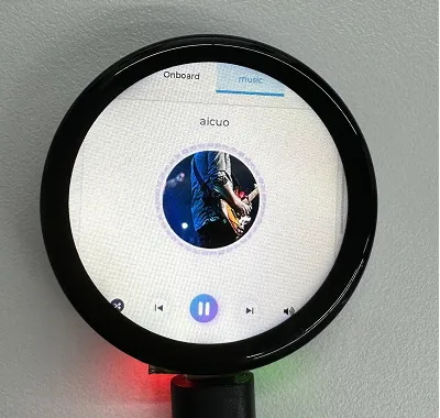
Page 2 is the UI page for playing mp3 audio files located in the root directory of the TF card
-
This program enables voice recognition by default. The wake word is "hi esp". After waking up, the backlight dims, and you can speak the command (if the backlight does not dim, it means it was not woken up; recognition requires standard pronunciation and a slower speaking pace)
-
Several MIC test audio formats are provided below (Note: if the "hi esp" wake-up fails, please reposition the audio to the point where the wake word is played and try again)
-
Please do not perform voice recognition while audio is being played through the speaker
-
The reason the test audio plays the wake word twice is that the current firmware version requires a focus step for the first wake-up (metaphorically), and the current firmware does not allow disabling this feature
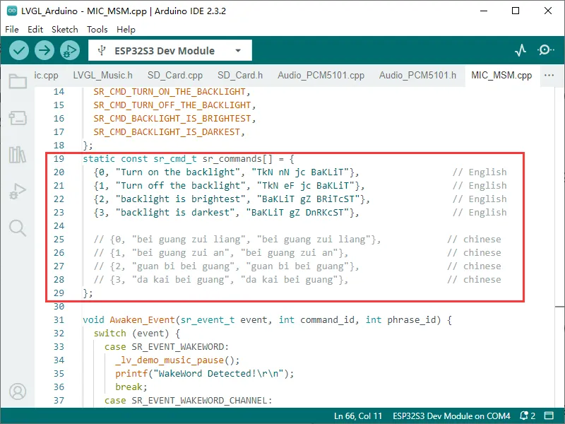
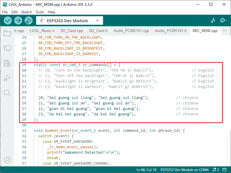
// CommandsTurn on the backlightTurn off the backlightBacklight is brightestBacklight is darkest
Example-v2
The Arduino examples are located in the Arduino/examples directory of the example package.
| Demo | Basic Program Description | Dependency Library |
|---|---|---|
| 01_lvgl_example | Demonstrates basic LVGL graphics library functionality, also useful for testing display basics and random text rendering | LVGL |
| 02_RTC_PCF85063 | RTC Clock Test | - |
| 03_audio_out_no_tf | Audio Playback Test | ESP32-audioI2S-master |
| 04_SDMMC_Test | TF Card Mount Test | - |
| 05_audio_out_tf | TF Card Audio Playback Test | ESP32-audioI2S-master |
| 06_AnalogRead | ADC Read Battery Voltage | - |
| 07_WiFi_http_Client | WIFI Connection and HTTP GET Test | - |
| 08_esp_sr | Voice Wake-up and Voice Recognition Function Test | - |
01_lvgl_example
Description
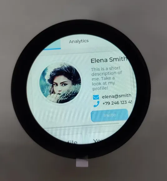
- This example demonstrates the functionality of LVGL Widgets. Different demos can be switched in the code to view the effects.
Hardware Connection
- Connect the development board to the computer
Code Analysis
setup: Responsible for initializing various hardware devices and the LVGL graphics library environmentI²CBus Initialization:I2C_Init()initializes theI²Cbus for communication with otherI²Cdevices- I/O Expander Initialization: Creates and initializes the I/O expander
TCA9554PWR_Init(0x00);, sets pin modes to output, and performs some initial pin state configurations - Backlight Initialization: Initializes the
PWMcontrollerBacklight_Init(); - Graphics Display Initialization: Initializes the graphics display device
LCD_Init();, then initializesLVGL, including registering a print callback function for debugging, initializing the display driver and input device driver. Creates and starts theLVGLtimer, and finally callslv_demo_widgets()to demonstrate LVGL's example widgets
Operation Result
-
LCD Screen Display
02_RTC_PCF85063
Description
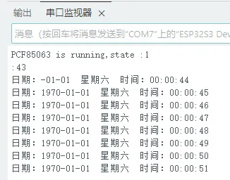
- This example demonstrates the functionality of the Real-Time Clock PCF85063A, retrieving the time every second and printing the current time to the serial port.
Hardware Connection
- Connect the development board to the computer
Code Analysis
- setup: Responsible for initializing various hardware peripherals
- Serial initialization:
USerial.begin(115200);prepares for serial debugging - I²C Bus Initialization:
I2C_Init()initializes the I²C bus for communication with other I²C devices - PCF85063 Chip Initialization:
PCF85063_Init();
- Serial initialization:
- loop:
- Reads Real-Time Clock data:
IPCF85063_Loop(); - Converts the data to a string and prints it to the LOG:
PCF85063_Loop();
- Reads Real-Time Clock data:
Operation Result
-
View the serial monitor
03_audio_out_no_tf
Description
- This example demonstrates how to initialize audio peripherals and play music.
Hardware Connection
- Connect the development board to the computer
Code Analysis
- setup: Responsible for initializing various hardware peripherals
- Serial initialization:
USerial.begin(115200);prepares for serial debugging - I²C Bus Initialization:
I2C_Init()initializes the I²C bus for communication with other I²C devices - Initializes the ES8311 audio decoder chip:
es8311_codec_init(); - Initializes the I2S peripheral:
setupI2S(); - Initializes the PA pin and sets it high: pinMode(15, OUTPUT);digitalWrite(15, HIGH); GPIO15 controls the amplifier enable output
- Serial initialization:
- loop:
- Reads audio data and outputs it to the ES8311 via I2S: i2s.write((uint8_t *)audio_data, AUDIO_SAMPLES * 2);
Operation Result
- This example has no screen display or LOG output
- After flashing the code, the audio will play in a loop
04_SDMMC_Test
Description
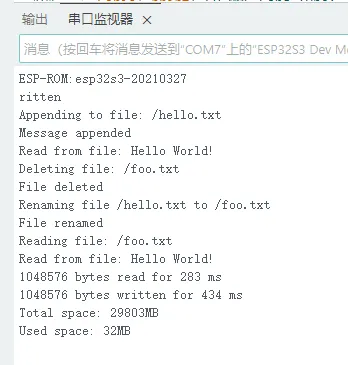
- This example demonstrates TF card mounting, prints TF card type information, and tests file reading and writing.
Hardware Connection
- Connect the development board to the computer
- Insert a TF card
Code Analysis
- setup: Responsible for initializing various hardware peripherals
- Serial initialization:
USerial.begin(115200);prepares for serial debugging - Initializes SDIO pins:
SD_MMC.setPins(clk, cmd, d0) - Mounts the TF card:
SD_MMC.begin("/sdcard", true) - Gets the TF card type:
SD_MMC.cardType(); - Gets the TF card capacity:
SD_MMC.cardSize() - Tests file writing:
writeFile(SD_MMC, "/hello.txt", "Hello ");
- Serial initialization:
Operation Result
-
View the serial monitor
05_audio_out_tf
Description
- This example demonstrates mounting a TF card and reading audio files from the TF card for playback.
Hardware Connection
- Connect the development board to the computer
- Insert a TF card with an MP3 file
Code Analysis
- setup: Responsible for initializing various hardware peripherals
- Serial initialization:
USerial.begin(115200);prepares for serial debugging - I²C Bus Initialization:
I2C_Init()initializes the I²C bus for communication with other I²C devices - Mounts the TF card:
sdmmc_init(); - Initializes the ES8311 audio decoder chip:
es8311_codec_init(); - Initializes audio I2S peripheral pins: audio.setPinout(I2S_BCK_PIN, I2S_LRCK_PIN, I2S_DOUT_PIN,I2S_MCLK_PIN);
- Sets the playback path: audio.connecttoFS(SD_MMC, "ff-16b-1c-44100hz.mp3");
- Initializes the PA pin and sets it high: pinMode(15, OUTPUT);digitalWrite(15, HIGH); GPIO15 controls the amplifier enable output
- Serial initialization:
- loop:
- Audio processing: audio.loop();
Operation Result
- This example has no screen display or LOG output
- After flashing the code, the audio will play in a loop
06_AnalogRead
Description
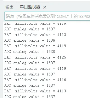
- This example demonstrates reading raw ADC values and battery voltage via ADC.
Hardware Connection
- Connect the development board to the computer
- Insert a battery
- The power switch needs to be turned on
Code Analysis
- setup: Responsible for initializing various hardware peripherals
- Serial initialization:
USerial.begin(115200);prepares for serial debugging - Initializes ADC peripheral:
analogReadResolution(12);
- Serial initialization:
- loop:
- Gets raw ADC value:
analogRead(8); - Gets the converted actual voltage value:
analogReadMilliVolts(8); - Prints battery voltage:
Serial.printf("BAT millivolts value = %d\n", analogVolts*3);. The battery voltage is detected via a resistor divider before being fed into the ADC
- Gets raw ADC value:
Operation Result
-
View the serial monitor
07_WiFi_http_Client
Description
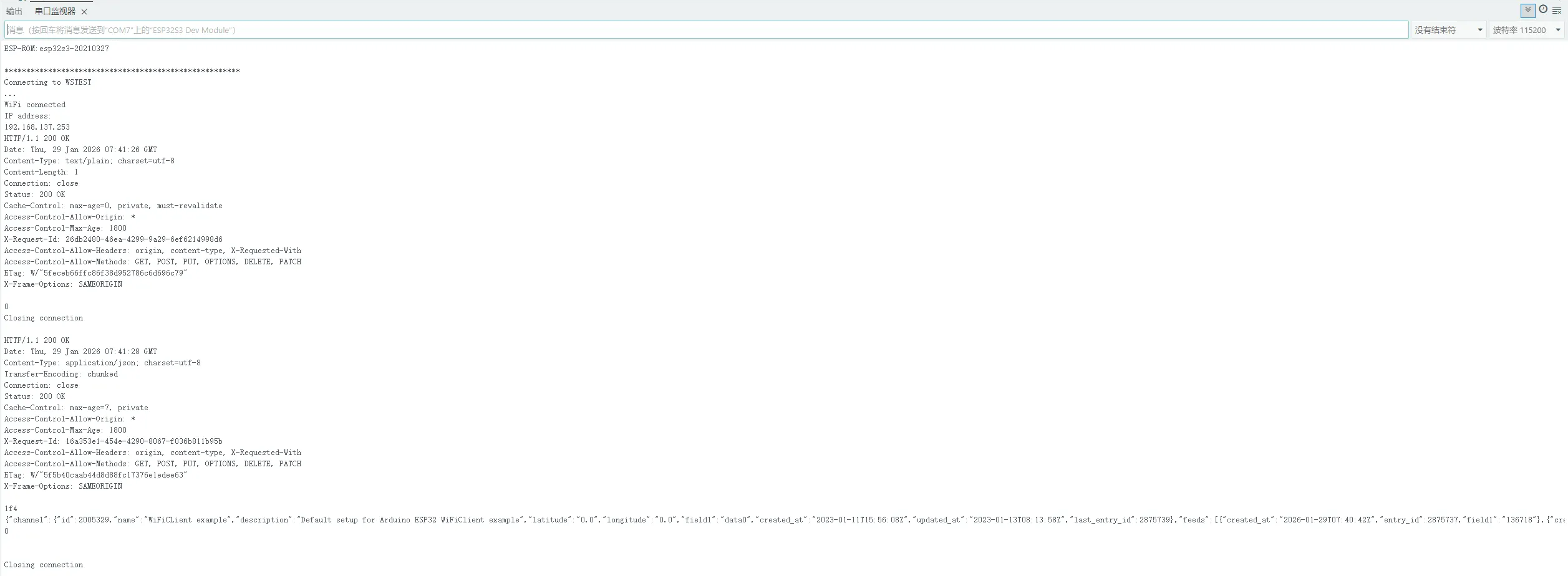
- This example demonstrates Wi-Fi connection and obtaining JSON data via the HTTP GET method.
Hardware Connection
- Connect the development board to the computer
Code Analysis
- setup: Responsible for initializing various hardware peripherals
- Sets the SSID for connection:
const char *ssid = "WSTEST"; - Sets the PASSWORD for connection:
const char *password = "waveshare0755"; - Serial initialization:
USerial.begin(115200);prepares for serial debugging - Wi-Fi initialization and connection:
WiFi.begin(ssid, password); - Prints IP address upon successful connection:
Serial.println(WiFi.localIP());
- Sets the SSID for connection:
- loop:
- Connects to HTTP server:
client.connect(host, httpPort); - Gets the response:
readResponse(&client);
- Connects to HTTP server:
Operation Result
-
View the serial monitor
08_esp_sr
Description
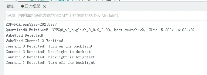
- This example demonstrates the voice wake-up and voice recognition features of ESP-SR.
Hardware Connection
- Connect the development board to the computer
Code Analysis
- setup: Responsible for initializing various hardware peripherals
- Serial initialization:
USerial.begin(115200);prepares for serial debugging - Initializes I2C:
Wire.begin(I2C_PIN_SDA, I2C_PIN_SCL); - ES7210 encoder initialization:
es7210_init(); - Sets I2S pins:
i2s.setPins(I2S_PIN_BCK, I2S_PIN_WS, I2S_PIN_DOUT, I2S_PIN_DIN, I2S_PIN_MCK); - Initializes I2S peripheral:
i2s.begin(I2S_MODE_STD, 16000, I2S_DATA_BIT_WIDTH_16BIT, I2S_SLOT_MODE_STEREO); - Sets voice wake-up and recognition event:
ESP_SR.onEvent(onSrEvent); - Initializes the ESP-SR speech recognition module: ESP_SR.begin(i2s, sr_commands, sizeof(sr_commands) / sizeof(sr_cmd_t), SR_CHANNELS_STEREO, SR_MODE_WAKEWORD);
- Serial initialization:
- onSrEvent(sr_event_t event, int command_id, int phrase_id): ESP-SR voice recognition callback event
- Connects to HTTP server:
client.connect(host, httpPort); - Gets the response:
readResponse(&client);
- Connects to HTTP server:
Operation Result
-
View the serial monitor
Switch between Chinese/English Recognition Models
The initial state of the environment defaults to the English recognition environment. Follow the steps below to switch to the Chinese recognition model or revert to the English recognition model.
Switch to Chinese Recognition Model
Building the Chinese Recognition Environment
- Download the provided program file Demo Using Chinese Model
- Navigate to the path
C:\Users\Waveshare\AppData\Local\Arduino15\packages\esp32\hardware\esp32\3.0.2\libraries\ESP_SR\src(where Waveshare is the computer username) - Replace the
esp32-hal-sr.cfile in this path with the downloaded file - Download the Chinese model Chinese Model - Wake Word 'hi lexin'
- Navigate to the path
C:\Users\Waveshare\AppData\Local\Arduino15\packages\esp32\tools\esp32-arduino-libs\idf-release_v5.1-bd2b9390ef\esp32s3\esp_sr(where Waveshare is the computer username) - Replace the
srmodels.binfile in this path with the downloaded file - Modify the recognition commands in the demo to Chinese commands (Pinyin)
Switching to English Recognition Model
Switching to English Recognition Model
- The initial state of the environment defaults to the English recognition environment. If it has not been switched to Chinese, do not perform the following modifications
- If it was previously modified for Chinese recognition, download the provided program file Demo Using English Model(https://files.waveshare.com/wiki/common/Use_the_English_model_program.zip)
- Navigate to the path
C:\Users\Waveshare\AppData\Local\Arduino15\packages\esp32\hardware\esp32\3.0.2\libraries\ESP_SR\src(where Waveshare is the computer username) - Replace the
esp32-hal-sr.cfile in this path with the downloaded file - Download the English model English Model - Wake Word 'hi esp’
- Navigate to the path
C:\Users\Waveshare\AppData\Local\Arduino15\packages\esp32\tools\esp32-arduino-libs\idf-release_v5.1-bd2b9390ef\esp32s3\esp_sr(where Waveshare is the computer username) - Replace the
srmodels.binfile in this path with the downloaded file - Modify the recognition commands in the demo to English commands (phonemes)