ESP-IDF
This chapter contains the following sections. Please read as needed:
ESP-IDF Getting Started
New to ESP32 ESP-IDF development and looking to get started quickly? We have prepared a general Getting Started Tutorial for you.
- Section 1: Environment Setup
- Section 2: Running Examples
- Section 3: Creating a Project
- Section 4: Using Components
- Section 5: Debugging
- Section 6: FreeRTOS
- Section 7: Peripherals
- Section 8: Wi-Fi Programming
- Section 9: BLE Programming
Please Note: This tutorial uses the ESP32-S3-Zero as a teaching example, and all hardware code is based on its pinout. Before you start, it is recommended that you check the pinout of your development board to ensure the pin configuration is correct.
Setting Up Development Environment
For the ESP32-S3-Touch-LCD-1.85C development board, ESP-IDF V5.5.1 or above is required.
The following guide uses Windows as an example, demonstrating development using VS Code + the ESP-IDF extension. macOS and Linux users should refer to the official documentation.
The screenshots in this section use ESP-IDF V5.5.2 as an example. When installing, please select the ESP-IDF version that matches your board's example.
Install the ESP-IDF Development Environment
-
Download the installation manager from the ESP-IDF Installation Manager page. This is Espressif's latest cross-platform installer. The following steps demonstrate how to use its offline installation feature.
Click the Offline Installer tab on the page, then select Windows as the operating system and the ESP-IDF version you need (the version shown in the screenshot is for reference only — choose the version that fits your actual needs).

After confirming your selection, click the download button. The browser will automatically download two files: the ESP-IDF Offline Package (.zst) and the ESP-IDF Installer (.exe).

Please wait for both files to finish downloading.
-
Once the download is complete, double-click to run the ESP-IDF Installer (eim-gui-windows-x64.exe).
The installer will automatically detect if the offline package exists in the same directory. Click Install from archive.

Next, select the installation path. We recommend using the default path. If you need to customize it, ensure the path does not contain Chinese characters or spaces. Click Start installation to proceed.

-
When you see the following screen, the ESP-IDF installation is successful.

-
We recommend installing the drivers as well. Click Finish installation, then select Install driver.

Install Visual Studio Code and the ESP-IDF Extension
-
Download and install Visual Studio Code.
-
During installation, it is recommended to check Add "Open with Code" action to Windows Explorer file context menu to facilitate opening project folders quickly.
-
In VS Code, click the Extensions icon
 in the Activity Bar on the side (or use the shortcut Ctrl + Shift + X) to open the Extensions view.
 -
Enter ESP-IDF in the search box, locate the ESP-IDF extension, and click Install.

-
For ESP-IDF extension versions ≥ 2.0, the extension will automatically detect and recognize the ESP-IDF environment installed in the previous steps, requiring no manual configuration.
Example-v1
| Demo | Basic Description |
|---|---|
| ESP32-S3-Touch-LCD-1.85C-Test | Test onboard device functionality |
ESP32-S3-Touch-LCD-1.85C-Test
Example Description
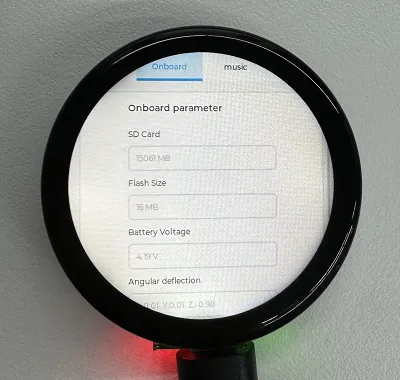
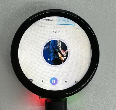
- This demo demonstrates the functionality of various onboard devices. Page 1 displays parameters such as SD Card, Flash Size, Battery Voltage, etc., while Page 2 is the music playback interface. Additionally, this example includes voice recognition functionality.
Hardware Connection
- Insert the TF card into the development board (can be used without a TF card)
- Connect the development board to the computer
Code Analysis
Driver_Init(): Initializes the resources required by the hardware, driver, and system, and creates a task to cyclically execute hardware drivers- Hardware Initialization: - Hardware Initialization:
Driver_Init()is responsible for initializing multiple hardware modules, such as power management, clock, I2C bus, external I/O, sensors, etc. - Task Creation:
xTaskCreatePinnedToCore()creates a FreeRTOS taskDriver_Loopand binds it to core 0. This means theDriver_Loopfunction will run in a continuous loop, handling hardware-related operations. This task runs concurrently with other tasks, aiding real-time performance of hardware drivers. - Modular Design: The initialization function distributes hardware initialization across different modules, making it easy to maintain and extend. If new hardware needs support, simply add the initialization code here.
- Hardware Initialization: - Hardware Initialization:
Driver_Loop(): This function runs cyclically in the FreeRTOS task, periodically executing the work of each hardware driver. It is the core component of most hardware driver operations- Cyclic Execution of Hardware Drivers:
Driver_Loop()periodically calls the loop functions of multiple hardware drivers, such asQMI8658_Loop(),PCF85063_Loop(),BAT_Get_Volts(), andPWR_Loop(). These are hardware operations that execute in real time.QMI8658_Loop(): Handles interaction with the QMI8658 sensor, reading sensor dataPCF85063_Loop(): Handles the PCF85063 clock module, updating the timeBAT_Get_Volts(): Gets the current battery voltage to ensure the device's battery level meets requirementsPWR_Loop(): Performs power management tasks, monitoring power status and controlling power on/off
- Cyclic Execution of Hardware Drivers:
- Timing Task: Using
vTaskDelay(pdMS_TO_TICKS(100)), theDriver_Loop()function delays every 100 milliseconds. This helps ensure the task does not consume excessive CPU resources and avoids too frequent hardware operations. - Delete Task:
vTaskDelete(NULL)is used to delete the current task, but sincewhile(1)is an infinite loop, this line of code is never executed
Operation Result
-
LCD Screen Display
-
LCD Screen Display Parameter Description
Parameter Function Description SD Card Displays the TF card size Connect a TF card. If recognition fails, please format the TF card to FAT32 (if initial recognition fails, wait a moment and then reset to check again) Flash Size Displays the Flash size Onboard 16MB Flash Battery Voltage Battery voltage Battery voltage can be detected when a battery is connected Angular deflection Displays the board's angular deviation Displays deviation in three directions RTC Time Displays RTC time Displays the current RTC time
The RTC time may not match the current time because data cannot be retained when power is off. To keep the RTC time accurate, you need to connect an RTC battery and update the RTC timeWireless scan Displays the number of Wi-Fi networks scanned It will be displayed at the end after the scan finishes Backlight brightness Brightness slider Adjusts screen brightness -
Page 2 is the UI page for playing mp3 audio files located in the root directory of the TF card
-
This program enables voice recognition by default. The wake word is "hi esp". After waking up, the backlight dims, and you can speak the command (if the backlight does not dim, it means it was not woken up; recognition requires standard pronunciation and a slower speaking pace)
-
Several MIC test audio formats are provided below (Note: if the "hi esp" wake-up fails, please reposition the audio to the point where the wake word is played and try again)
-
Please do not perform voice recognition while audio is being played through the speaker
-
The reason the test audio plays the wake word twice is that the current firmware version requires a focus step for the first wake-up (metaphorically), and the current firmware does not allow disabling this feature
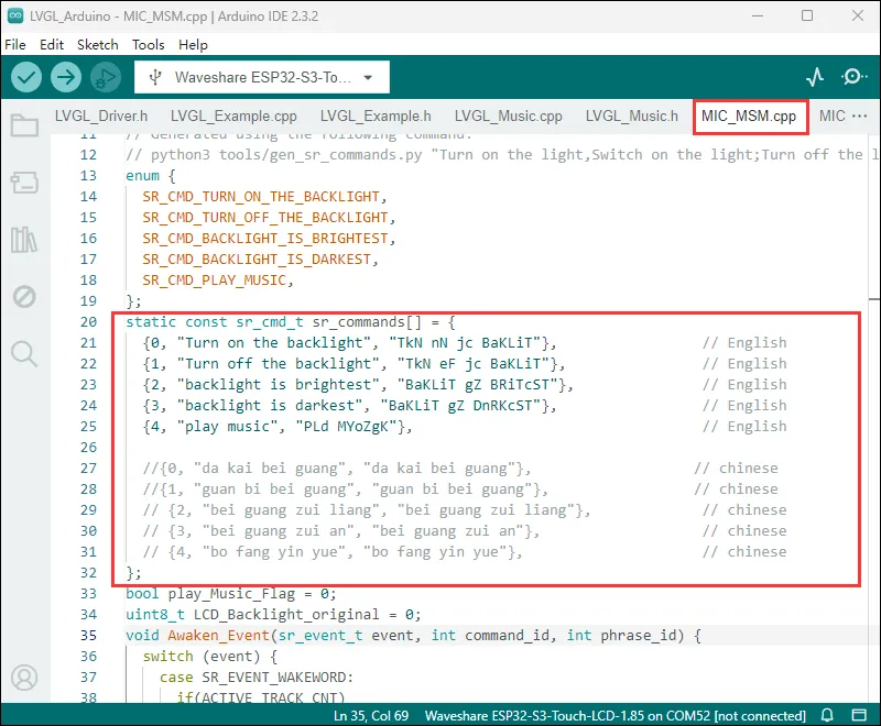
// CommandsTurn on the backlightTurn off the backlightBacklight is brightestBacklight is darkest
Example-v2
| Demo | Basic Description |
|---|---|
| ESP32-S3-Touch-LCD-1.85C_V2-Test | Test onboard device functionality |
ESP32-S3-Touch-LCD-1.85C_V2-Test
Example Description
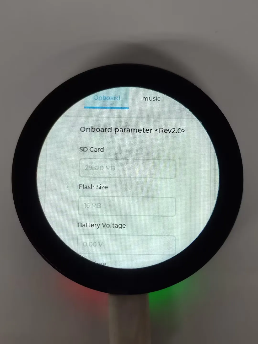
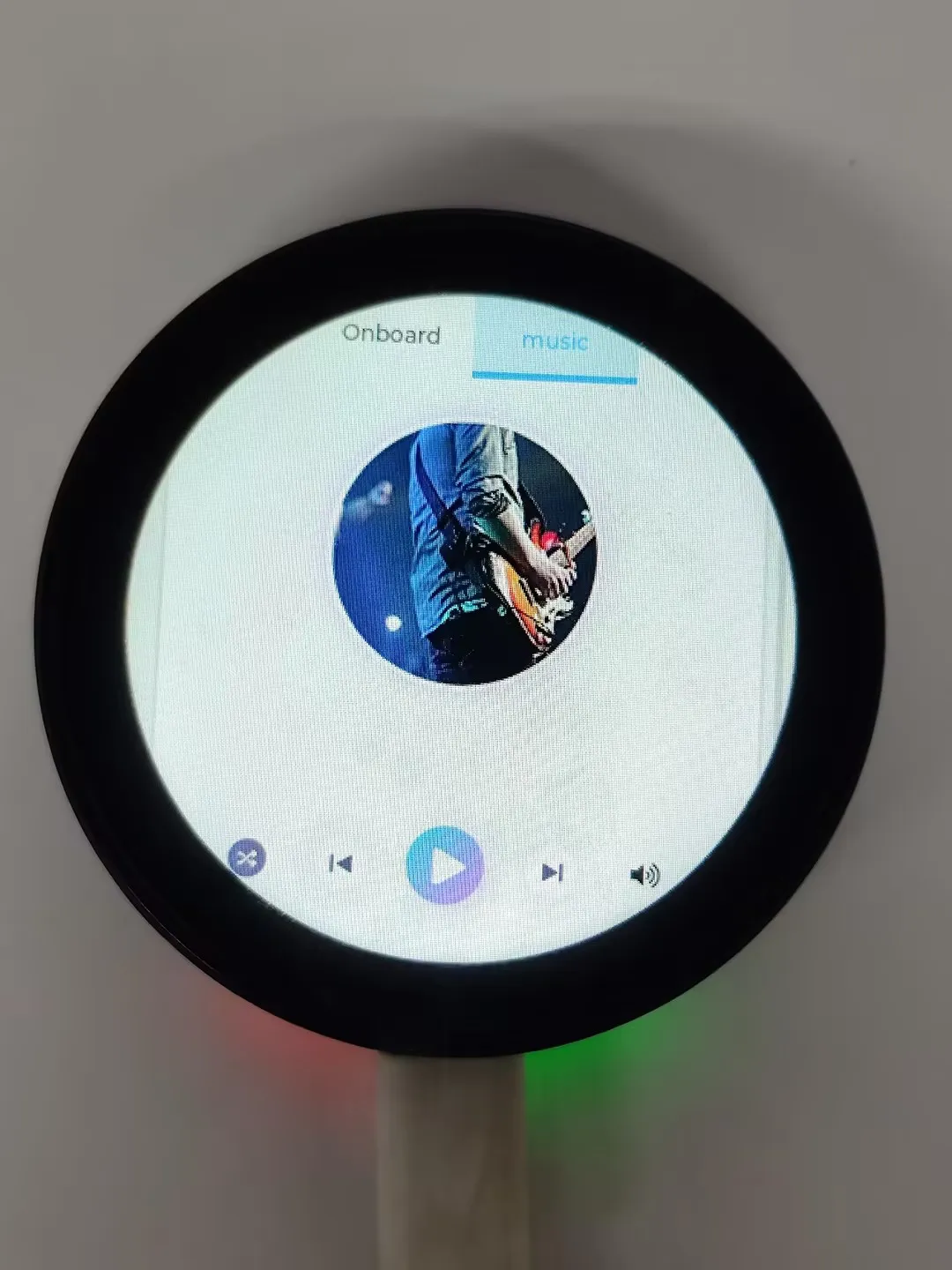
- This demo demonstrates the functionality of various onboard devices. Page 1 displays parameters such as SD Card, Flash Size, Battery Voltage, etc., while Page 2 is the music playback interface. Additionally, this example includes voice recognition functionality.
Hardware Connection
- Insert the TF card into the development board (can be used without a TF card)
- Connect the development board to the computer
Code Analysis
Driver_Init(): Initializes the resources required by the hardware, driver, and system, and creates a task to cyclically execute hardware drivers- Hardware Initialization: - Hardware Initialization:
Driver_Init()is responsible for initializing multiple hardware modules, such as power management, clock, I2C bus, external I/O, sensors, etc. - Task Creation:
xTaskCreatePinnedToCore()creates a FreeRTOS taskDriver_Loopand binds it to core 0. This means theDriver_Loopfunction will run in a continuous loop, handling hardware-related operations. This task runs concurrently with other tasks, aiding real-time performance of hardware drivers. - Modular Design: The initialization function distributes hardware initialization across different modules, making it easy to maintain and extend. If new hardware needs support, simply add the initialization code here.
- Hardware Initialization: - Hardware Initialization:
Driver_Loop(): This function runs cyclically in the FreeRTOS task, periodically executing the work of each hardware driver. It is the core component of most hardware driver operations- Cyclic Execution of Hardware Drivers:
Driver_Loop()periodically calls the loop functions of multiple hardware drivers, such asQMI8658_Loop(),PCF85063_Loop(),BAT_Get_Volts(), andPWR_Loop(). These are hardware operations that execute in real time.QMI8658_Loop(): Handles interaction with the QMI8658 sensor, reading sensor dataPCF85063_Loop(): Handles the PCF85063 clock module, updating the timeBAT_Get_Volts(): Gets the current battery voltage to ensure the device's battery level meets requirementsPWR_Loop(): Performs power management tasks, monitoring power status and controlling power on/off
- Cyclic Execution of Hardware Drivers:
- Timing Task: Using
vTaskDelay(pdMS_TO_TICKS(100)), theDriver_Loop()function delays every 100 milliseconds. This helps ensure the task does not consume excessive CPU resources and avoids too frequent hardware operations. - Delete Task:
vTaskDelete(NULL)is used to delete the current task, but sincewhile(1)is an infinite loop, this line of code is never executed
Operation Result
-
LCD Screen Display
-
LCD Screen Display Parameter Description
Parameter Function Description SD Card Displays the TF card size Connect a TF card. If recognition fails, please format the TF card to FAT32 (if initial recognition fails, wait a moment and then reset to check again) Flash Size Displays the Flash size Onboard 16MB Flash Battery Voltage Battery voltage Battery voltage can be detected when a battery is connected Angular deflection Displays the board's angular deviation Displays deviation in three directions RTC Time Displays RTC time Displays the current RTC time
The RTC time may not match the current time because data cannot be retained when power is off. To keep the RTC time accurate, you need to connect an RTC battery and update the RTC timeWireless scan Displays the number of Wi-Fi networks scanned It will be displayed at the end after the scan finishes Backlight brightness Brightness slider Adjusts screen brightness -
Page 2 is the UI page for playing mp3 audio files located in the root directory of the TF card
-
This program enables voice recognition by default. The wake word is "hi esp". After waking up, the backlight dims, and you can speak the command (if the backlight does not dim, it means it was not woken up; recognition requires standard pronunciation and a slower speaking pace)
-
Several MIC test audio formats are provided below (Note: if the "hi esp" wake-up fails, please reposition the audio to the point where the wake word is played and try again)
-
Music playback and voice recognition can be used simultaneously; when a wake word is detected, the music pauses and automatically resumes after a timeout
-
The reason the test audio plays the wake word twice is that the current firmware version requires a focus step for the first wake-up (metaphorically), and the current firmware does not allow disabling this feature
// CommandsTurn on the backlightTurn off the backlightBacklight is brightestBacklight is darkest
Switch between Chinese/English Recognition Models
- The initial state of the environment defaults to the English recognition environment. Follow the steps below to switch to the Chinese recognition model or the English recognition model
- Switch to Chinese/English Recognition Model
- If the following two files exist in the project, delete them

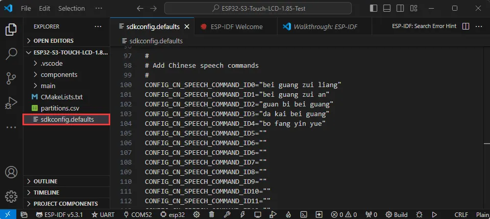
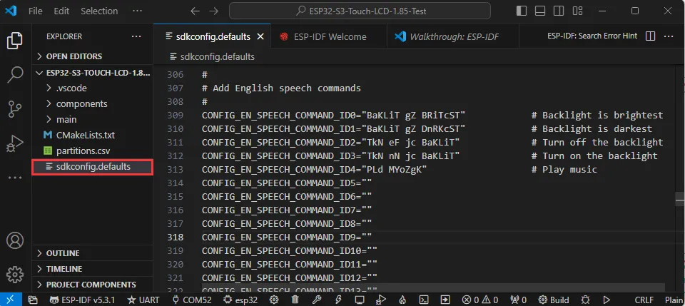
- Go to the file sdkconfig.defaults and locate this section
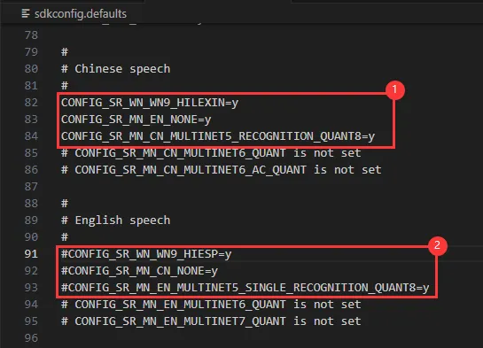
- Comment out ① with "#" to switch to the English recognition model
- Comment out ② with "#" to switch to the Chinese recognition model
- If the following two files exist in the project, delete them
- Switch to Chinese/English Recognition Model
Generate Voice Control Commands
Environment Preparation
- Check if Python is installed on the computer
- Open the command line: Win+R -> enter cmd
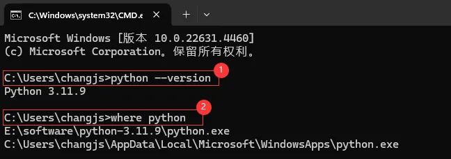
- ①. Enter
python --version. If a Python version number appears, it means it is installed - ②. Enter
where pythonto view the Python installation location- The Python environment under the C drive is the one automatically installed when VS Code was installed
- The environment under the E drive is the Python environment used for the following steps
- ①. Enter
If the environment is not installed, please refer to Python Environment Installation Tutorial. If already installed, please continue.
- Enter
pip install g2p_enat the command line to install the g2p_en package - Install the resource package and place it in the corresponding user's
C:\Users\username\AppData\Roamingpath. Double-click to extract the file - Enter
pip install pypinyinat the command line to install the pypinyin library
Generate Chinese Pinyin
- Download the Chinese command generation file
- Switch the command line path to the Chinese command generation folder (the path varies by user; the following is for reference only)
cd /d E:\download\Generate_Chinese_command
- Execute
multinet_pinyin.pyat the command line to generate Chinese PinyinExample:python multinet_pinyin.py "要转为拼音的中文"python multinet_pinyin.py "你好微雪电子"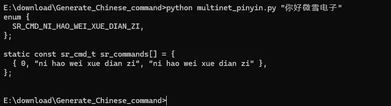
Generate English Phonemes
- Download the English command generation file
- Switch the command line path to the English command generation folder (the path varies by user; the following is for reference only)
cd /d E:\download\Generate_English_command
- Execute
gen_sr_commands.pyat the command line to generate phoneme commandsExample:python gen_sr_commands.py "English to be converted to phonemes"python gen_sr_commands.py "hello waveshare"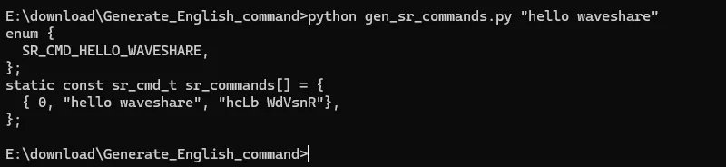
Modify Commands
- Under Arduino
- Under ESP-IDF
- Chinese Commands
- English Commands
- Chinese Commands