ESP-IDF
This chapter contains the following sections. Please read as needed:
ESP-IDF Getting Started
New to ESP32 ESP-IDF development and looking to get started quickly? We have prepared a general Getting Started Tutorial for you.
- Section 1: Environment Setup
- Section 2: Running Examples
- Section 3: Creating a Project
- Section 4: Using Components
- Section 5: Debugging
- Section 6: FreeRTOS
- Section 7: Peripherals
- Section 8: Wi-Fi Programming
- Section 9: BLE Programming
Please Note: This tutorial uses the ESP32-S3-Zero as a teaching example, and all hardware code is based on its pinout. Before you start, it is recommended that you check the pinout of your development board to ensure the pin configuration is correct.
Setting Up the Development Environment
For the ESP32-S3-Touch-LCD-3.49 development board, the examples default to ESP-IDF V5.5.3. If compilation fails with other versions, you can fall back to this version for testing.
The following guide uses Windows as an example, demonstrating development using VS Code + the ESP-IDF extension. macOS and Linux users should refer to the official documentation.
The screenshots in this section use ESP-IDF V5.5.2 as an example. When installing, please select the ESP-IDF version that matches your board's example.
Install the ESP-IDF Development Environment
-
Download the installation manager from the ESP-IDF Installation Manager page. This is Espressif's latest cross-platform installer. The following steps demonstrate how to use its offline installation feature.
Click the Offline Installer tab on the page, then select Windows as the operating system and the ESP-IDF version you need (the version shown in the screenshot is for reference only — choose the version that fits your actual needs).

After confirming your selection, click the download button. The browser will automatically download two files: the ESP-IDF Offline Package (.zst) and the ESP-IDF Installer (.exe).

Please wait for both files to finish downloading.
-
Once the download is complete, double-click to run the ESP-IDF Installer (eim-gui-windows-x64.exe).
The installer will automatically detect if the offline package exists in the same directory. Click Install from archive.

Next, select the installation path. We recommend using the default path. If you need to customize it, ensure the path does not contain Chinese characters or spaces. Click Start installation to proceed.

-
When you see the following screen, the ESP-IDF installation is successful.

-
We recommend installing the drivers as well. Click Finish installation, then select Install driver.

Install Visual Studio Code and the ESP-IDF Extension
-
Download and install Visual Studio Code.
-
During installation, it is recommended to check Add "Open with Code" action to Windows Explorer file context menu to facilitate opening project folders quickly.
-
In VS Code, click the Extensions icon
 in the Activity Bar on the side (or use the shortcut Ctrl + Shift + X) to open the Extensions view.
 -
Enter ESP-IDF in the search box, locate the ESP-IDF extension, and click Install.

-
For ESP-IDF extension versions ≥ 2.0, the extension will automatically detect and recognize the ESP-IDF environment installed in the previous steps, requiring no manual configuration.
Example
Please note: there are V1 and V2 variants. The programs (pins have been modified) are not common. It is recommended to download the corresponding example program according to your actual product version.
| Example | Basic Program Description | Dependency Library |
|---|---|---|
| 01_ADC_Test | Get the voltage value of the lithium battery | - |
| 02_I2C_PCF85063 | Print real-time time of RTC chip | SensorLib |
| 03_I2C_QMI8658 | Print the raw data from IMU | SensorLib |
| 04_SD_Card | Load and display the information of the TF card | - |
| 05_WIFI_AP | Set to AP mode to obtain the IP address of the access device | - |
| 06_WIFI_STA | Set to STA mode to connect to Wi-Fi and obtain an IP address | - |
| 07_BATT_PWR_Test | Control power via the PWR button when powered solely by the lithium battery | - |
| 08_Audio_Test | Play the sound recorded by the microphone through the speaker | - |
| 09_LVGL_V8_Test | LVGLV8 example | LVGL V8.4.0 |
| 10_LVGL_V9_Test | LVGLV9 example | LVGL V9.3.0 |
| 11_FactoryProgram | Comprehensive example | LVGL V8.3.11 |
01_ADC_Test
Example Description
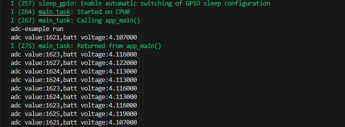
- The analog voltage connected through the GPIO is converted to digital by the ADC, and then the actual lithium battery voltage is calculated and printed to the terminal.
Hardware Connection
- Connect the board to the computer using a USB cable.
Code Analysis
adc_bsp_init(void): Initializes ADC1, including creating an ADC one-shot trigger unit and configuring Channel 3 of ADC1.adc_get_value(float *value,int *data): Reads the value from Channel 3 of ADC1, calculates the corresponding voltage based on the reference voltage and resolution, and stores it at the location pointed to by the passed pointer. Stores 0 if the read fails.adc_example(void* parameter): After initializing ADC1, creates an ADC task. This task reads the ADC value every second and calculates the system voltage from the raw ADC reading.
Operation Result
-
After the program is compiled and downloaded, you can view the printed ADC values and voltage output by opening the Serial Monitor, as shown in the following image:
02_I2C_PCF85063
Example Description
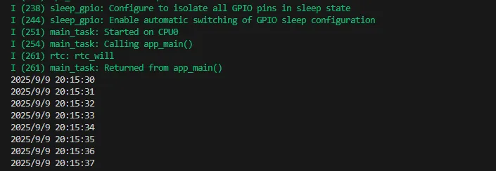
- Through the I2C protocol, initialize the PCF85063 chip, set the time, and then periodically read the time and print it to the terminal
Hardware Connection
- Connect the board to the computer using a USB cable.
Code Analysis
void i2c_rtc_loop_task(void *arg): Creates an RTC task to implement the RTC function, reading the clock of the RTC chip every second and outputting it to the terminal.
Operation Result
-
After the program is compiled and downloaded, open the serial port monitoring to see the RTC time of the printout, as shown in the following figure:
03_I2C_QMI8658
Example Description
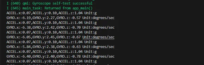
- Initialize the QMI8658 chip via the I2C protocol, then read the corresponding attitude information every 200ms and print it to the terminal.
Hardware Connection
- Connect the board to the computer using a USB cable.
Code Analysis
void i2c_qmi_loop_task(void *arg): Creates a QMI task to acquire attitude information. The task reads and prints accelerometer and gyroscope data at 200ms intervals, and outputs the results to the serial console.
Operation Result
-
Open the serial monitor to view the raw data output from the IMU (Euler angles require conversion), as shown in the figure below:
04_SD_Card
Example Description
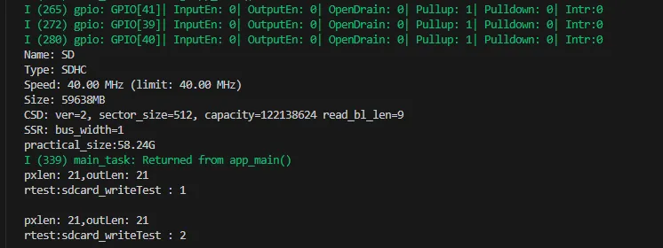
- Drive the TF card through SDMMC, and print the TF card information to the terminal after successfully mounting.
Hardware Connection
- Install a FatFs-formatted TF card into the board before powering on
Code Analysis
-
sdcard_init(void): Initializes the TF card using 1-line SDMMC mode. -
sdcard_loop_task(void *arg): A task to test TF card read/write functionality. You need to uncomment the#define sdcard_write_Testmacro definition.//#define sdcard_write_Test
Operation Result
-
Click on the serial port monitoring device, you can see the output information of the TF card, as shown in the figure below:
05_WIFI_AP
Example Description
- This example can set the development board as a hotspot, allowing phones or other devices in STA mode to connect to the development board.
Hardware Connection
- Connect the board to the computer using a USB cable.
Code Analysis
-
In the file
softap_example_main.c, findSSIDandPASSWORD, and then your phone or other device in STA mode can use the SSID and PASSWORD to connect to the development board.#define EXAMPLE_ESP_WIFI_SSID "waveshare_esp32"#define EXAMPLE_ESP_WIFI_PASSWORD "wav123456"
Operation Result
-
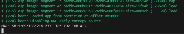
After flashing the program, open the Serial Terminal. If a device successfully connects to the hotspot, it will output the device's MAC address and IP address, as shown in the figure:
06_WIFI_STA
Example Description
- This example configures the development board as a STA device to connect to a router, thereby accessing the system network.
Hardware Connection
- Connect the board to the computer using a USB cable.
Code Analysis
-
In the file
esp_wifi_bsp.c, findssidandpassword, then modify them to the SSID and Password of an available router in your current environment.wifi_config_t wifi_config = {.sta = {.ssid = "PDCN",.password = "1234567890",},};
Operation Result
-
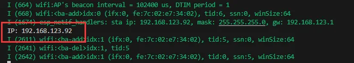
After flashing the program, open the Serial Terminal. If the device successfully connects to the hotspot, the obtained IP address will be output, as shown in the figure:
07_BATT_PWR_Test
Example Description
- Demonstrates how to control the system power via the PWR button when powered by the lithium battery.
Hardware Connection
- Connect the board to the computer using a USB cable.
Code Analysis
setup_ui(lv_ui *ui): Initializes the UI interface for visual control.tca9554_init(): Initialize the lithium battery control IO port.button_Init(): Initialize buttons and various trigger events.example_button_pwr_task(void* parmeter): Task that waits for button event triggers.
Operation Result
-
After the program is flashed, disconnect the USB power supply and connect the lithium battery. Power on by pressing and holding the PWR button, as shown in the figure:
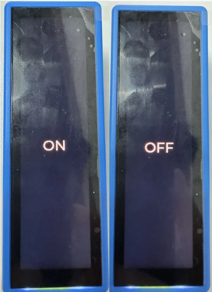 tip
tip- Press and hold the PWR button, wait for the screen to display "On", which means that the startup is successful, and release the button
- Press and hold the PWR button again, wait for the screen to display "Off", which means that the power is turned off successfully, and release the button
08_Audio_Test
Example Description
- Demonstrates how to get data from the microphone and then play it through the speaker
Hardware Connection
- Connect the board to the computer using a USB cable.
Code Analysis
i2c_master_Init(): Initializes the I2C bus.tca9554_init(): Initializes the I/O ports for audio amplifier CTRL control.lvgl_port_init(): Initializes the LVGL interface.user_audio_bsp_init(): Initializes the audio interface.
Operation Result
-
After the program is flashed, as shown in the figure:
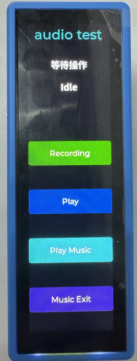 tip
tip- Click Recording to enter recording mode, speak into the MIC, and it will automatically end after 3 seconds
- Click Play to play the sound you just recorded
- Click Play Music to play a piece of music
- Click Music Exit to interrupt music playback
09_LVGL_V8_Test
Example Description
- Helps users quickly implement UI design by porting LVGL V8.
Hardware Connection
- Connect the board to the computer using a USB cable.
Code Analysis
-
If a 90-degree display rotation is needed, locate the
#define Rotatedmacro in theuser_config.hfile and assign the value"USER_DISP_ROT_90". -
If backlight testing is required, locate the
#define Backlight_Testingmacro in theuser_config.hfile and assign the value"true".#define Backlight_Testing 0#define USER_DISP_ROT_90 1#define USER_DISP_ROT_NONO 0#define Rotated USER_DISP_ROT_NONO //Rotation via software
Operation Result
-
After the program is flashed, the device operation result is as follows:
10_LVGL_V9_Test
Example Description
- Helps users quickly implement UI design by porting LVGL V9.
Hardware Connection
- Connect the board to the computer using a USB cable.
Code Analysis
-
If a 90-degree display rotation is needed, locate the
#define Rotatedmacro in theuser_config.hfile and assign the value"USER_DISP_ROT_90". -
If backlight testing is required, locate the
#define Backlight_Testingmacro in theuser_config.hfile and assign the value"true".#define Backlight_Testing 0#define USER_DISP_ROT_90 1#define USER_DISP_ROT_NONO 0#define Rotated USER_DISP_ROT_NONO //Rotation via software
Operation Result
-
After the program is flashed, the device operation result is as follows:
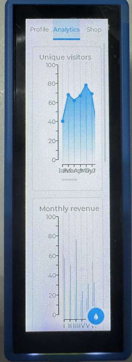
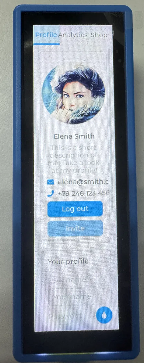
11_FactoryProgram
Example Description
- Comprehensive project, you can simply test the onboard hardware functions, or directly use the BIN firmware we provide for flashing.
Hardware Connection
- Connect the board to the computer using a USB cable.
Code Analysis
setup_ui(&src_ui);            // Set up the UI interface
lcd_bl_pwm_bsp_init(LCD_PWM_MODE_255);  // Initialize LCD backlight PWM, using 255-level brightness adjustment mode
tca9554_init();                  // Initialize TCA9554 GPIO expander chip
button_Init();                       // Initialize buttons
adc_bsp_init();                  // Initialize ADC for voltage detection
i2c_rtc_setup();                  // Setup RTC (real-time clock)
i2c_rtc_setTime(2025,7,7,18,43,30);  // Set RTC time to 2025-07-07 18:43:30
i2c_imu_setup();                // Setup IMU (inertial measurement unit)
_sdcard_init();                    // Initialize TF card
espwifi_init();                      // Initialize WiFi function
user_audio_bsp_init();      // Initialize user audio onboard support
audio_play_init();                // Initialize audio playback function
Operation Result
-
After the program is flashed, the device operation result is as follows:
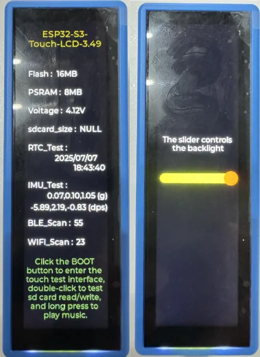 tip
tip- Use the main interface to determine whether the onboard hardware is functioning properly.
- Swipe left to control the backlight
-
Touch and Audio control interface, as shown:
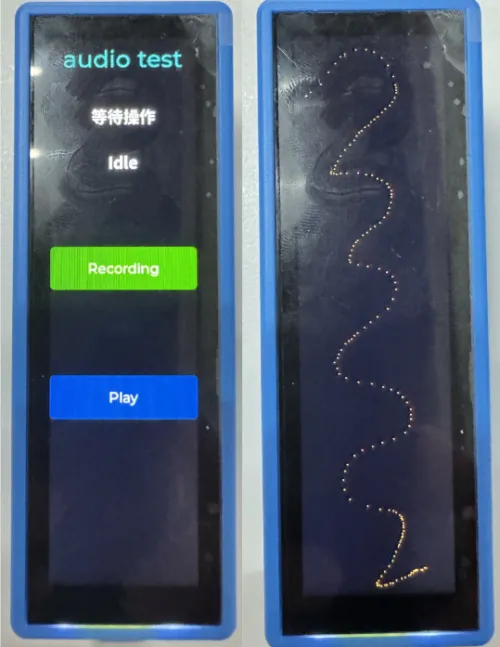 tip
tip- Long press the BOOT button to enter the audio interface, where you can test recording and playback functions. Long press the BOOT button again to return to the main interface.
- Click the BOOT button to enter the Touch interface, where you can draw Touch trajectories.