Working with Arduino
This chapter contains the following sections. Please read as needed:
Arduino Getting Started
New to Arduino ESP32 development and looking for a quick start? We have prepared a comprehensive Getting Started Tutorial for you.
- Section 0: Getting to Know ESP32
- Section 1: Installing and Configuring Arduino IDE
- Section 2: Arduino Basics
- Section 3: Digital Output/Input
- Section 4: Analog Input
- Section 5: Pulse Width Modulation (PWM)
- Section 6: Serial Communication (UART)
- Section 7: I2C Communication
- Section 8: SPI Communication
- Section 9: Wi-Fi Basics
- Section 10: Web Server
- Section 11: Bluetooth
- Section 12: LVGL GUI Development
- Section 13: Comprehensive Project
Note: This tutorial uses the ESP32-S3-Zero as a reference example, and all hardware code is based on its pinout. Before you start, we recommend checking the pinout of your development board to ensure the pin configuration is correct.
Setting Up the Development Environment
1. Installing and Configuring the Arduino IDE
Please refer to the tutorial Installing and Configuring Arduino IDE to download and install the Arduino IDE and add ESP32 support.
2. Installing Libraries
- When installing Arduino libraries, there are typically two methods: online installation and offline installation. If the library installation requires offline installation, you must use the provided library files.
- For most libraries, users can easily search for and install them via the Arduino IDE's online Library Manager. However, some open-source or custom libraries are not synchronized to the Arduino Library Manager and therefore cannot be found through online search. In this case, users can only install these libraries manually via offline methods.
- The example package for the ESP32-S3-Touch-LCD-3.5B development board can be downloaded from here. The
Arduino\librariesdirectory within the package already contains all the library files required for this tutorial.
| Library/File Name | Description | Version | Installation Method |
|---|---|---|---|
| LVGL | Graphics library | v8.4.0 | "Online installation" (requires copying the demos folder to src) |
| GFX_Library_for_Arduino | LCD driver library | v1.5.5 | "Online Installation" |
| XPowersLib | Power management driver library | v0.2.9 | "Online Installation" |
| SensorLib | Sensor library | v0.3.1 | "Online Installation" |
| ESP32-audioI2S-master | Audio processing | v3.3.0 | "Online Installation" |
| TCA9554 | I/O expander library | v0.1.2 | "Online Installation" |
| OneButton | Button library | v2.6.1 | "Online Installation" |
| esp_lcd_touch_axs15231b | Touch driver | - | "Offline Installation" |
| es8311 | es8311 driver library | - | "Offline Installation" |
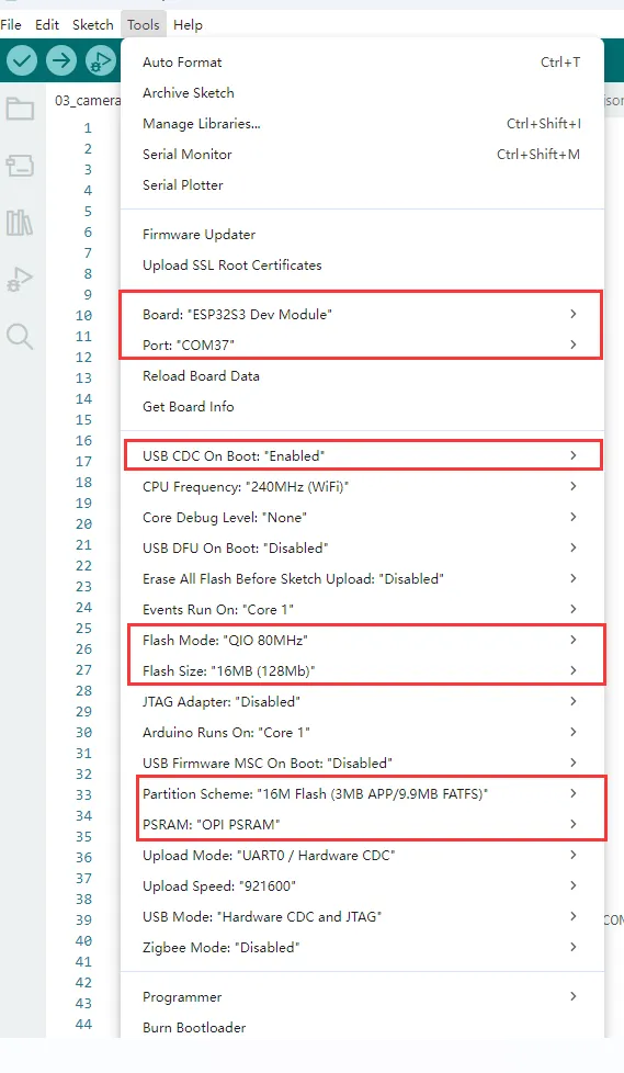
3. Arduino Project Parameter Settings
Example
The Arduino examples are located in the Arduino/examples directory of the example package.
| Example | Basic Program Description | Dependency Library |
|---|---|---|
| 01_audio_out | Read audio file from TF card and play it | ESP32-audioI2S-master |
| 02_axp2101_example | Print data from the power management chip | XPowersLib |
| 03_button_example | Single-click, double-click, long-press, etc., on the BOOT button | OneButton |
| 04_es8311_example | Record audio for a period of time and play it back | es8311 |
| 05_pcf85063_example | Print RTC data | SensorLib |
| 06_qmi8658_example | Print IMU data | SensorLib |
| 07_sd_test | Test TF card read/write | - |
| 08_gfx_helloworld | Display HelloWorld on the screen | GFX_Library_for_Arduino, TCA9554 |
| 09_lvgl_example_v8 | LVGL v8 example program | lvgl (v8.4.0), GFX_Library_for_Arduino, TCA9554, esp_lcd_touch_axs15231b |
| 10_lvgl_example_v9 | LVGL v9 example program | lvgl (v9.2.2), GFX_Library_for_Arduino, TCA9554, esp_lcd_touch_axs15231b |
| 11_camera_web_server | Display camera image on a web page | XPowersLib |
01_audio_out
Example Description
- This example demonstrates the ESP32-S3-Touch-LCD-3.5B reading an audio file from the TF card and playing it through a speaker, supporting MP3, AAC, WAV, and other formats.
Hardware Connection
- Insert the TF card into the computer.
- Copy the music file
1.mp3to the TF card. - Insert the TF card into ESP32-S3-Touch-LCD-3.5B
Code Analysis
-
Set the audio file to play
audio.connecttoFS(SD_MMC, "1.mp3");
Operation Result
- The device will play auido directly without showing content on the screen
02_axp2101_example
Example Description
- This example demonstrates using XPowers to drive the AXP2101 and printing data via the serial port.
Hardware Connection
- Connect the board to your computer via USB.
Code Analysis
-
Initialize
bool result = power.begin(Wire, AXP2101_SLAVE_ADDRESS, i2c_sda, i2c_scl);if (result == false) {Serial.println("power is not online...");while (1) delay(50);}
Operation Result
-
The screen shows no output
-
Open the serial monitor

03_button_example
Example Description
- This example demonstrates using the OneButton library to drive the BOOT button and prints events such as single-click, double-click, and long-press via the serial port.
Hardware Connection
- Connect the board to your computer via USB.
Code Analysis
-
Bind callback functions
button1.attachClick(click1);button1.attachDoubleClick(doubleclick1);button1.attachLongPressStart(longPressStart1);button1.attachLongPressStop(longPressStop1);button1.attachDuringLongPress(longPress1);
Operation Result
-
The screen shows no output
-
Open the serial monitor

04_es8311_example
Example Description
- This example demonstrates using the ESP32-S3-Touch-LCD-3.5B to drive the ES8311 audio codec to implement audio recording and playback.
Hardware Connection
- Connect the board to your computer via USB.
Code Analysis
-
Initialize
Wire.begin(I2C_SDA, I2C_SCL);es8311_codec_init();setupI2S(); -
Record audio for 5 seconds and play back the recorded content:
wav_buffer = i2s.recordWAV(5, &wav_size);delay(1000);Serial.println("I2S playWAV");i2s.playWAV(wav_buffer, wav_size);
Operation Result
- The screen shows no output
- Press the RST button on the ESP32-S3-Touch-LCD-3.5B to start recording; playback begins 2 seconds later.
05_pcf85063_example
Example Description
- This example demonstrates driving the PCF85063 on the ESP32-S3-Touch-LCD-3.5B to set the time/date and read the time.
Hardware Connection
- Connect the board to your computer via USB.
Code Analysis
-
Initialize
if (!rtc.begin(Wire, PCF85063_SLAVE_ADDRESS, SENSOR_SDA, SENSOR_SCL)) {Serial.println("Failed to find PCF8563 - check your wiring!");while (1) {delay(1000);}} -
Set the time and date
rtc.setDateTime(year, month, day, hour, minute, second); -
Get the time and date
RTC_DateTime datetime = rtc.getDateTime();
Operation Result
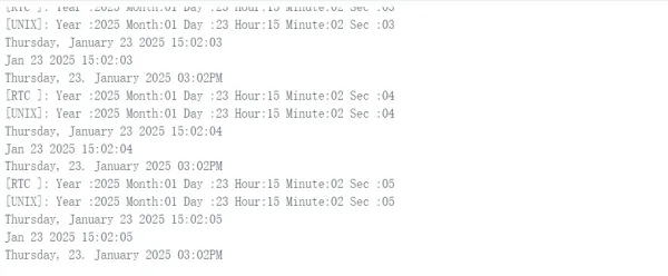
-
The screen shows no output
-
Open the serial monitor
06_qmi8658_example
Example Description
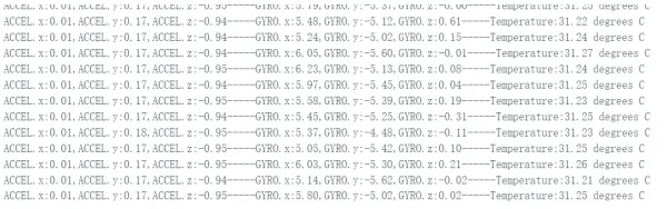
- This example demonstrates driving the QMI8658 on the ESP32-S3-Touch-LCD-3.5B to read and print accelerometer, gyroscope, and IMU temperature data.
Hardware Connection
- Connect the board to your computer via USB.
Code Analysis
-
Initialize
if (!qmi.begin(Wire, QMI8658_L_SLAVE_ADDRESS, SENSOR_SDA, SENSOR_SCL)) {Serial.println("Failed to find QMI8658 - check your wiring!");while (1) {delay(1000);}} -
Get data
if (qmi.getDataReady()) {if (qmi.getAccelerometer(acc.x, acc.y, acc.z)) {}if (qmi.getGyroscope(gyr.x, gyr.y, gyr.z)) {}}
Operation Result
-
The screen shows no output
-
Open the serial monitor
07_sd_test
Example Description
- This example demonstrates testing TF card read/write functionality on the ESP32-S3-Touch-LCD-3.5B.
Hardware Connection
- Connect the board to the computer.
- Insert the TF card into the card slot (TF card needs to be formatted as FAT32).
Code Analysis
-
Initialize
if(!SD_MMC.setPins(clk, cmd, d0)){Serial.println("Pin change failed!");return;}if (!SD_MMC.begin( "/sdcard", true)) {Serial.println("Card Mount Failed");return;}
Operation Result
- Insert the TF card into the computer, and and two files, test.txt and foo.test, will appear. The content of the foo.txt is Hello World!, and the test.txt is empty.

08_gfx_helloworld
Example Description
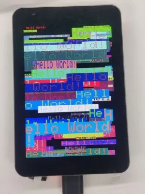
- This example demonstrates using the GFX_Library_for_Arduino library to drive the screen and display "HelloWorld" on the screen.
Hardware Connection
- Connect the board to the computer.
Code Analysis
-
Configure the screen interface and resolution, etc.
Arduino_DataBus *bus = new Arduino_ESP32QSPI(LCD_QSPI_CS, LCD_QSPI_CLK, LCD_QSPI_D0, LCD_QSPI_D1, LCD_QSPI_D2, LCD_QSPI_D3);Arduino_GFX *g = new Arduino_AXS15231B(bus, -1 /* RST */, 0 /* rotation */, false, 320, 480);Arduino_Canvas *gfx = new Arduino_Canvas(320, 480, g, 0, 0, ROTATION);
Operation Result
09_lvgl_example_v8
Example Description
- This example demonstrates running the LVGL (v8.4.0) example program on the ESP32-S3-Touch-LCD-3.5B.
Hardware Connection
- Connect the board to the computer.
Preparation
- LVGL v8.4.0 must be installed. If another version is installed, please reinstall it.

Code Analysis
-
UI initialization
lv_obj_t *label = lv_label_create(lv_scr_act());lv_label_set_text(label, "Hello Arduino! (V" GFX_STR(LVGL_VERSION_MAJOR) "." GFX_STR(LVGL_VERSION_MINOR) "." GFX_STR(LVGL_VERSION_PATCH) ")");lv_obj_align(label, LV_ALIGN_CENTER, 0, 0);lv_obj_t *sw = lv_switch_create(lv_scr_act());lv_obj_align(sw, LV_ALIGN_TOP_MID, 0, 50);sw = lv_switch_create(lv_scr_act());lv_obj_align(sw, LV_ALIGN_BOTTOM_MID, 0, -50);
Operation Result

10_lvgl_example_v9
Example Description
- This example demonstrates running the LVGL (v9.2.2) example program on the ESP32-S3-Touch-LCD-3.5B.
Hardware Connection
- Connect the board to the computer.
Preparation
- LVGL v9.2.2 must be installed. If another version is installed, please reinstall it.

Code Analysis
-
UI initialization
lv_obj_t *label = lv_label_create(lv_scr_act());lv_label_set_text(label, "Hello Arduino, I'm LVGL!(V" GFX_STR(LVGL_VERSION_MAJOR) "." GFX_STR(LVGL_VERSION_MINOR) "." GFX_STR(LVGL_VERSION_PATCH) ")");lv_obj_align(label, LV_ALIGN_CENTER, 0, 0);lv_obj_t *sw = lv_switch_create(lv_scr_act());lv_obj_align(sw, LV_ALIGN_TOP_MID, 0, 50);sw = lv_switch_create(lv_scr_act());lv_obj_align(sw, LV_ALIGN_BOTTOM_MID, 0, -50);
Operation Result

11_camera_web_server
Example Description
- This example demonstrates how to drive the camera. After connecting to Wi-Fi, the program creates a web server. Users simply enter the device's IP address in a browser to access it. The web page can display the camera image and supports settings such as resolution and mirroring.
Hardware Connection
- Connect the board to the computer.
- Insert the OV5640 camera into the 24Pin header on the board (not required for the version with a case).
Preparation
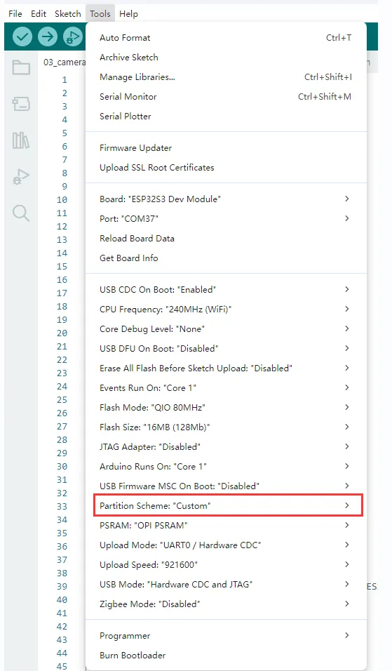
- Set Parttion to Custom.
Code Analysis
-
Define camera-related pins
#define PWDN_GPIO_NUM -1#define RESET_GPIO_NUM -1#define XCLK_GPIO_NUM 38#define SIOD_GPIO_NUM 8#define SIOC_GPIO_NUM 7#define Y9_GPIO_NUM 21#define Y8_GPIO_NUM 39#define Y7_GPIO_NUM 40#define Y6_GPIO_NUM 42#define Y5_GPIO_NUM 46#define Y4_GPIO_NUM 48#define Y3_GPIO_NUM 47#define Y2_GPIO_NUM 45#define VSYNC_GPIO_NUM 17#define HREF_GPIO_NUM 18#define PCLK_GPIO_NUM 41 -
Wi-Fi SSID and password to connect to
const char *ssid = "waveshare";const char *password = "12345678"; -
Start the server to begin providing an HTTP video stream
startCameraServer();Serial.print("Camera Ready! Use 'http://");Serial.print(WiFi.localIP());Serial.println("' to connect");
Operation Result
-
Open the serial terminal; after connecting to Wi-Fi, the IP address is shown.

-
Enter the IP address printed on the serial port in a browser (on the device that provides the hotspot).
-
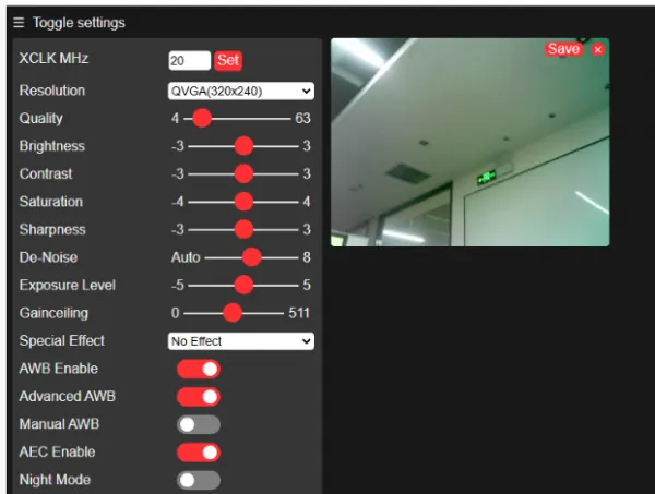
Click "Start Stream" to see the camera image.