Working with Arduino
This chapter contains the following sections. Please read as needed:
Arduino Getting Started
New to Arduino ESP32 development and looking for a quick start? We have prepared a comprehensive Getting Started Tutorial for you.
- Section 0: Getting to Know ESP32
- Section 1: Installing and Configuring Arduino IDE
- Section 2: Arduino Basics
- Section 3: Digital Output/Input
- Section 4: Analog Input
- Section 5: Pulse Width Modulation (PWM)
- Section 6: Serial Communication (UART)
- Section 7: I2C Communication
- Section 8: SPI Communication
- Section 9: Wi-Fi Basics
- Section 10: Web Server
- Section 11: Bluetooth
- Section 12: LVGL GUI Development
- Section 13: Comprehensive Project
Note: This tutorial uses the ESP32-S3-Zero as a reference example, and all hardware code is based on its pinout. Before you start, we recommend checking the pinout of your development board to ensure the pin configuration is correct.
Setting Up Development Environment
1. Installing and Configuring Arduino IDE
Please refer to the tutorial Installing and Configuring Arduino IDE to download and install the Arduino IDE and add ESP32 support.
2. Installing Libraries
To run the demo, you need to install the corresponding library.
You can click this link to download the example package for the ESP32-S3-Touch-LCD-4.3 development board. The Arduino\libraries directory within this package contains all the necessary library files required for this tutorial.
| Library/File Name | Description | Version | Installation Method |
|---|---|---|---|
| ESP32_Display_Panel | Display panel control library for ESP32 microcontrollers | v0.1.4 or higher | "Install Online" or "Install Offline" |
| ESP32_IO_Expander | I/O expander library for ESP32 | v0.0.4 or higher | "Install Online" or "Install Offline" |
| lvgl | LVGL graphics library | v8.4.0 | Install via library manager or manually |
| lv_conf.h | LVGL configuration file | —— | Install manually |
There are strong dependencies between versions of LVGL and its driver libraries. For example, a driver written for LVGL v8 may not be compatible with LVGL v9. To ensure that the examples can be reproduced reliably, it is recommended to use the specific versions listed in the table above. Mixing different versions of libraries may lead to compilation failures or runtime errors.
Installation Steps:
- Unzip the downloaded example package.
- Copy all folders from its
Arduino\librariesdirectory to your Arduino libraries folder.
The path to the Arduino libraries folder is typically: c:\Users\<username>\Documents\Arduino\libraries.
You can also locate it in the Arduino IDE by going to File > Preferences and checking the "Sketchbook location". The libraries folder is the libraries subfolder within this path.
- For other installation methods, please refer to: Arduino Library Management Tutorial.
3. Arduino Project Parameter Settings
Example
The Arduino examples are located in the example package.
| Demo | Basic Program Description | Dependency Library |
|---|---|---|
| 01_I2C_Test | Test I2C header | - |
| 02_RS485_Test | Test I2C header | - |
| 03_SD_Test | Test TF card slot | - |
| 04_Sensor_AD | Test ADC header | - |
| 05_UART_Test | Test UART | - |
| 06_TWAItransmit | Test CAN header | - |
| 07_TWAIreceive | Test CAN header | - |
| 08_DrawColorBar | Test RGB screen | ESP32_Display_Panel |
| 09_lvgl_Porting | Test LVGL porting | LVGL, ESP32_Display_Panel |
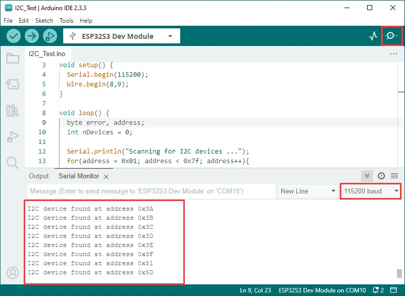
01_I2C_Test
This example tests if the I2C header is working properly: it scans for device addresses on the I2C bus and outputs the scan results.
Hardware Connection
- Connect the board to the computer using a USB cable
Code Analysis
loop():- The
loop()function is the main program loop. Its core function is to scan for devices on the I2C bus. - It first defines variables to store error codes, device addresses, and a counter for found devices.
- It then iterates through possible I2C device addresses from
0x01to0x7F. For each address, it starts a transmission to the device usingWire.beginTransmission(address)and ends the transmission usingWire.endTransmission(), capturing the error code. - If the error code is
0, it indicates an I2C device was found at that address. It prints the device address and increments the device count. If the error code is not2(which indicates no device responded), it prints the error code and the corresponding address. - Finally, if no I2C devices are found, it prints a corresponding message and uses
delay(5000)to pause the program for 5 seconds before scanning again.
- The
Example Flashing
- Select the board model ESP32S3 Dev Module and the port
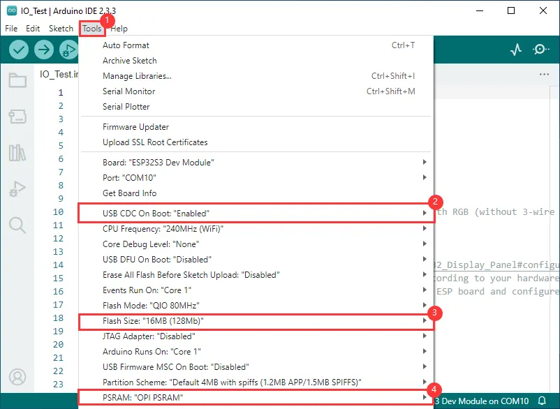
- Set the board parameters
- Flash the demo
Operation Result
-
The serial monitor prints the device address on the I2C bus
02_RS485_Test
This example demonstrates how to perform a serial loopback test using RS485 (it echoes back whatever is sent).
Hardware Connection
-
Connect the board to the computer using a USB cable
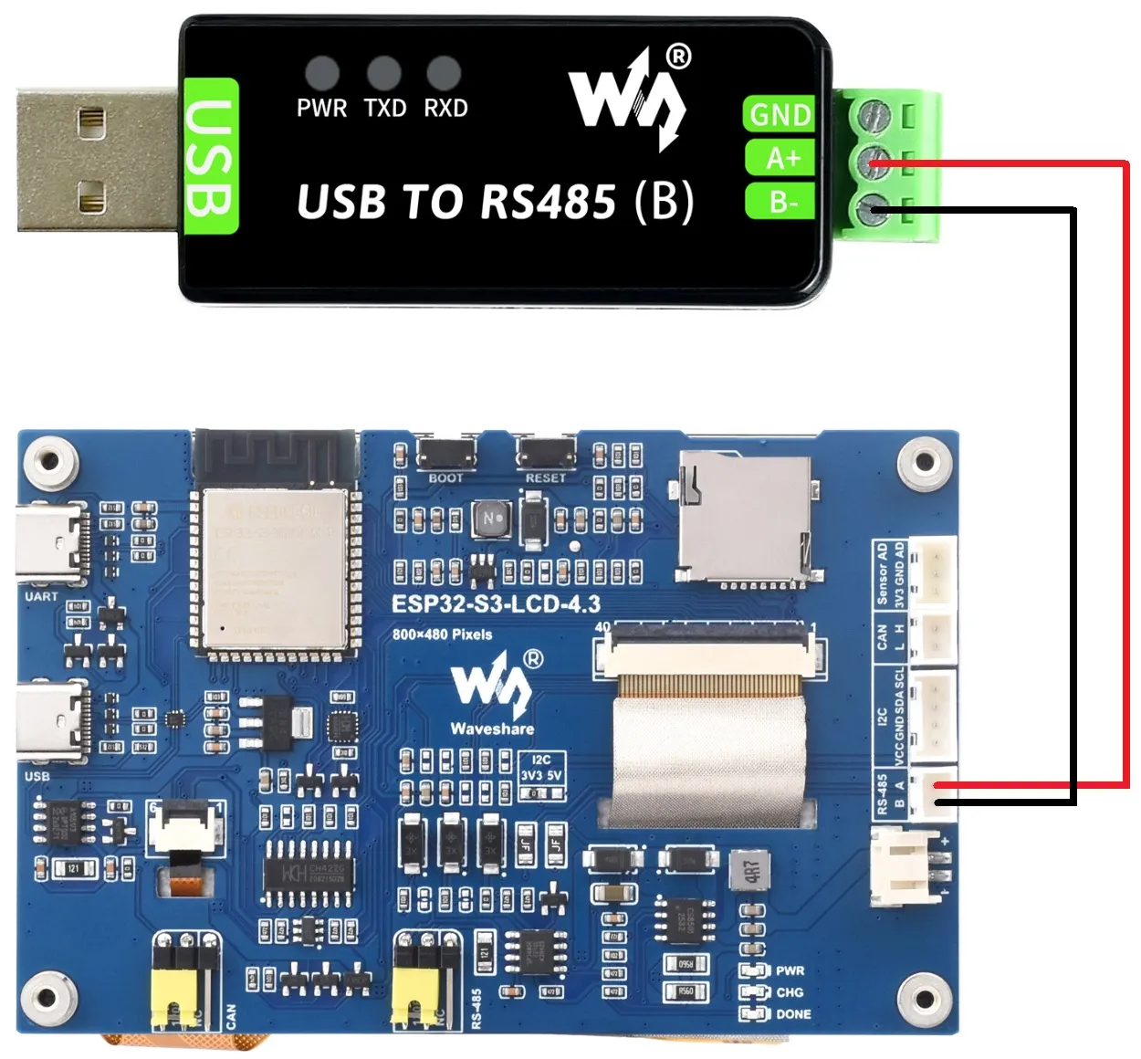
-
Connect the development board to a USB-to-RS485 converter
Code Analysis
-
setup():- The setup function mainly initializes serial communication.
- It initializes Serial1 using
RS485.begin, setting the baud rate, data format, and specifying receive and transmit pins. It then loops to ensure the serial initialization is successful.
-
loop():- The loop function is the main program loop. Its main function is to implement simple data echoing over RS485.
- It checks if data is available on the serial port. If data is available, it reads one byte and immediately sends it back, achieving the functionality of echoing received RS485 data.
Example Flashing
- Select the board model ESP32S3 Dev Module and the port
- Set the board parameters
- Flash the demo
Operation Result
-
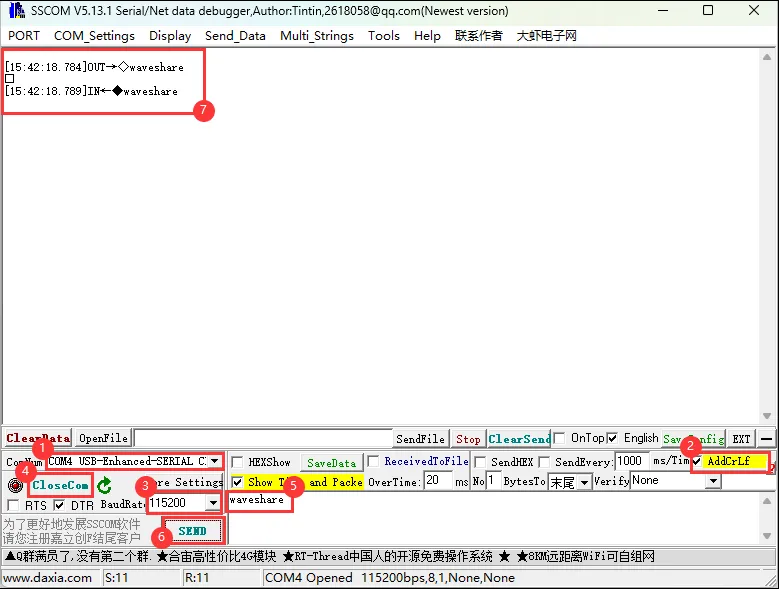
Open the serial debugging assistant and send a message to the ESP32-S3-Touch-LCD-4.3; the device will return the received message to the serial debugging assistant.
03_SD_Test
This example demonstrates how to mount a TF card and perform basic read/write and directory traversal tests.
Hardware Connection
-
Connect the board to the computer using a USB cable
-
Insert the TF card into the board
Code Analysis
setup():- The setup function performs a series of initialization operations and TF card tests.
- First, it initializes serial communication with a baud rate of 115200. It then creates an
ESP_IOExpander_CH422Gobject to manage expanded I/O pins, initializes them, and sets multiple pins to output mode, controlling the states of pins like touch screen reset (TP_RST), LCD backlight (LCD_BL), LCD reset (LCD_RST), TF card chip select (SD_CS), and USB select (USB_SEL). - Next, it uses the expanded GPIO pins to interface with the TF card, initializes SPI communication, and attempts to mount the TF card. If mounting fails, it prints an error message and returns. If successful, it detects and prints the TF card type and its size information.
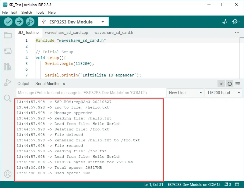
- Subsequently, it performs a series of file system operation tests, including listing directory contents, creating a directory, removing a directory, writing to a file, appending content to a file, reading a file, deleting a file, renaming a file, and testing file input/output. It finally prints the total space and used space of the TF card.
Example Flashing
- Select the board model ESP32S3 Dev Module and the port
- Set the board parameters
- Flash the demo
Operation Result
-
The ESP32-S3-Touch-LCD-4.3 will identify the TF card type and size, then perform file operations such as adding, deleting, modifying, and querying files.
04_Sensor_AD
This example tests the ADC connector.
Hardware Connection
-
Connect the board to the computer using a USB cable
-
Connect the PH2.0 to 2.54mm male connector to the Sensor AD interface of the board
Code Analysis
-
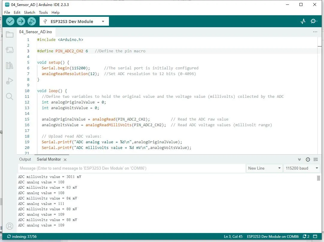
setup():- The setup function first initializes serial communication, then initializes the ADC with a resolution of 12 bits (0-4096).
-
loop():- The loop function reads the current AD value every 100ms and prints the current AD value.
Example Flashing
- Select the board model ESP32S3 Dev Module and the port
- Set the board parameters
- Flash the demo
Operation Result
-
The development board will set the ADC resolution, read the current AD value, and print it to the serial terminal.
05_UART_Test
This example tests UART: received data is echoed back (loopback).
Hardware Connection
- Connect the UART port of the board to the computer using a USB cable
Code Analysis
-
setup():- The setup function mainly initializes serial communication.
- It initializes the Serial port using
UART.begin, setting the baud rate, data format, and specifying receive and transmit pins. It then loops to ensure the serial initialization is successful.
-
loop():- The loop function is the main program loop. Its main function is to implement simple UART data echoing.
- It checks if data is available on the serial port. If data is available, it reads one byte and immediately sends it back, achieving the functionality of echoing received UART data.
Example Flashing
- Select the board model ESP32S3 Dev Module and the port
- Set the board parameters
- Flash the demo
Operation Result
-
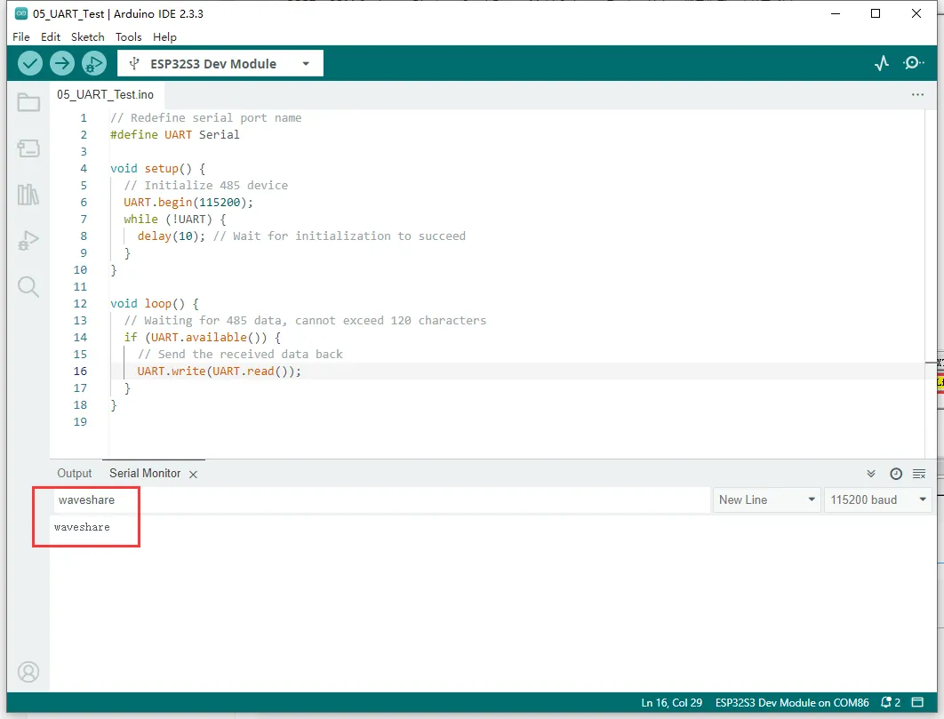
Open the serial debugging assistant and send a message to the ESP32-S3-Touch-LCD-4.3; the device will return the received message to the serial debugging assistant.
06_TWAItransmit
This example tests the CAN header: initializes the TWAI driver and periodically sends CAN frames.
Hardware Connection
-
Connect the board to the computer using a USB cable
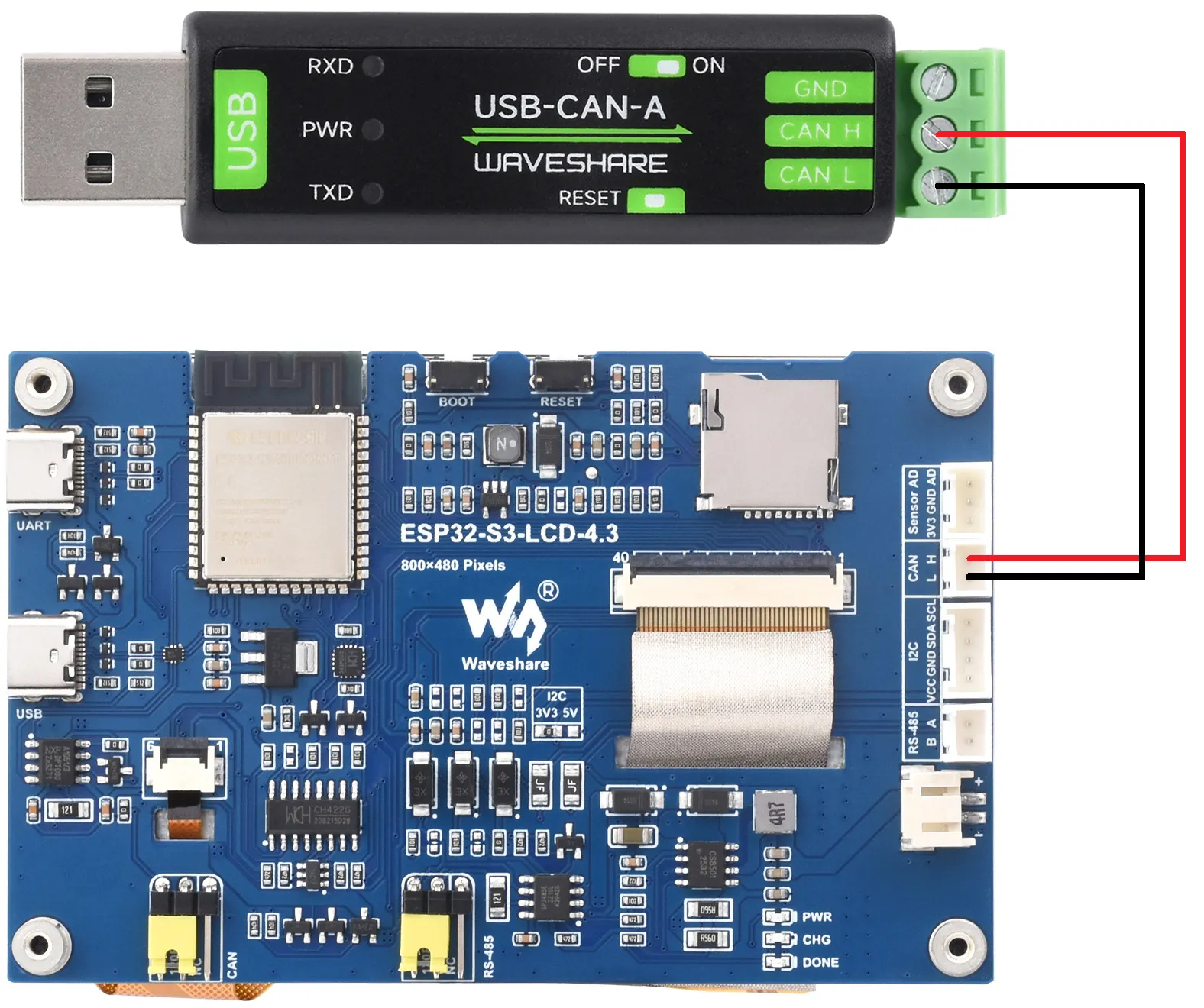
-
Connect the development board to a USB-CAN-A interface

Code Analysis
waveshare_twai_transmit():- The
waveshare_twai_transmit()function handles TWAI (an interface similar to CAN bus) transmission and alert processing. - First, it checks if any alerts have occurred. It reads triggered alerts using
twai_read_alertsand retrieves TWAI status information into atwai_status_info_tstructure. It then handles different triggered alerts accordingly. For example, if an error passive alert, bus error alert, transmission failure alert, or transmission success alert is triggered, it prints corresponding messages and outputs status information such as bus error count, number of pending messages, transmission error counter, and transmission failure count. - Next, it gets the current time (in milliseconds) and checks if it is time to send a message. If the time difference between the current time and the last send time is greater than or equal to the set transmission interval
TRANSMIT_RATE_MS, it updates the last send time and calls thesend_messagefunction to send a message. Thesend_messagefunction configures and queues a message with a specific identifier, data length, and data content for transmission. It prints a success message if queuing is successful, otherwise a failure message, and clears the message data array after sending.
- The
Example Flashing
- Select the board model ESP32S3 Dev Module and the port
- Set the board parameters
- Flash the demo
Operation Result
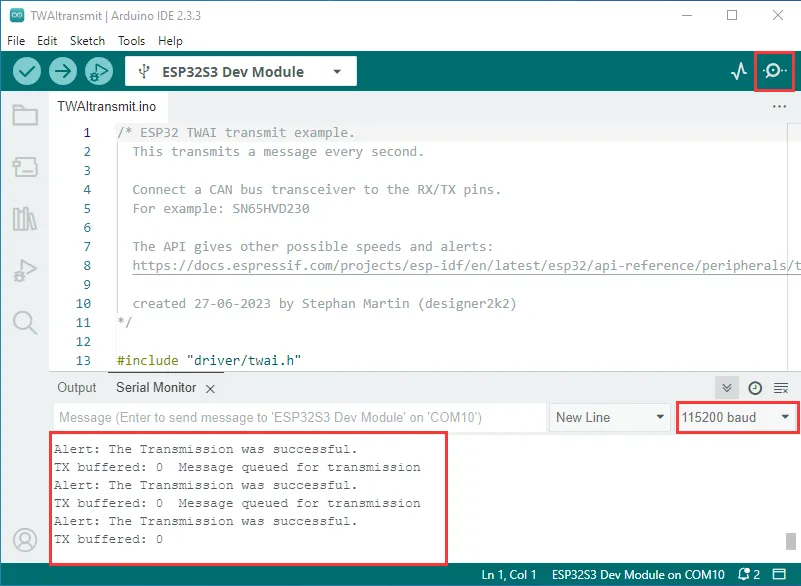
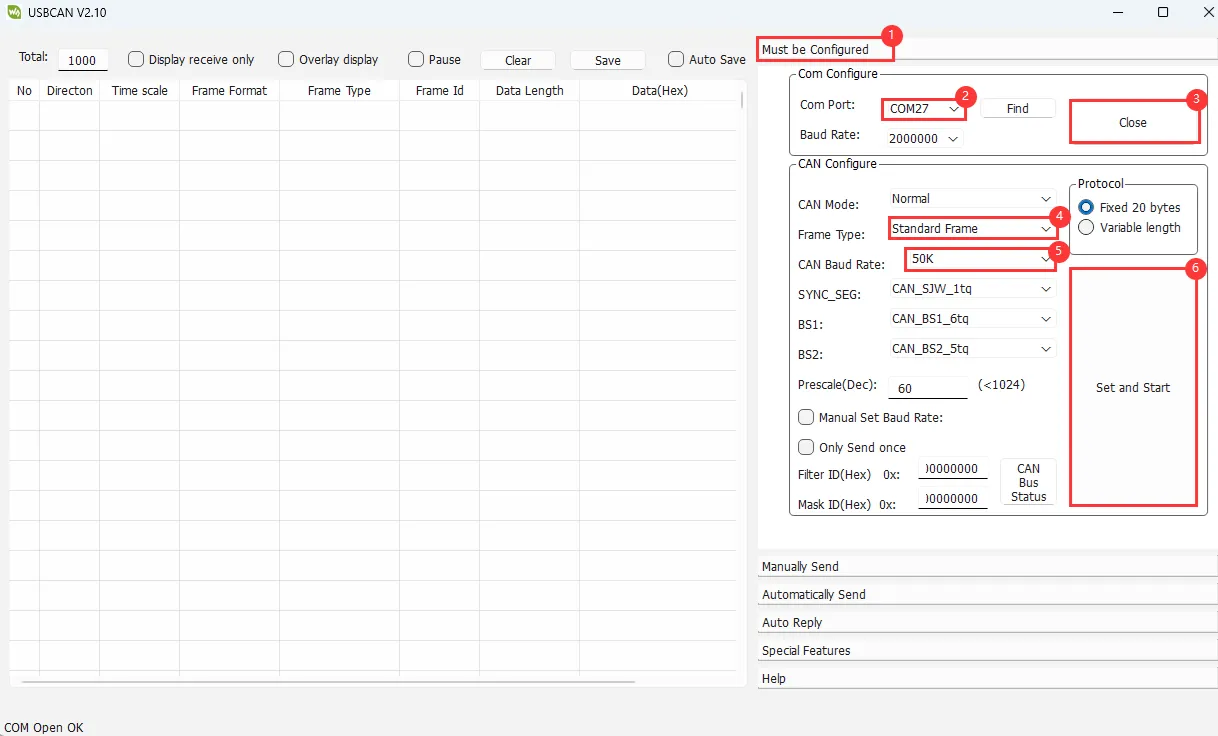
-
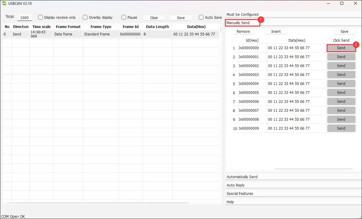
The serial port prints successful CAN message sends. After configuring the USB-CAN-A_TOOL and starting it, you can see the CAN messages sent by the ESP32-S3-Touch-LCD-4.3.
07_TWAIreceive
This example tests the CAN header: initializes the TWAI driver and receives CAN frames.
Hardware Connection
-
Connect the board to the computer using a USB cable
-
Connect the development board to a USB-CAN-A interface
Code Analysis
waveshare_twai_receive():- It first reads triggered alerts and retrieves status information, handling different alert conditions appropriately, such as printing error passive, bus error, receive queue full alerts and related counts.
- When a receive data alert is triggered, it loops to receive messages and calls the
handle_rx_messagefunction to process them. This function determines the message format and prints the message identifier and data content (for non-remote transmission requests). This effectively handles received messages and alert responses on the TWAI bus.
Example Flashing
- Select the board model ESP32S3 Dev Module and the port
- Set the board parameters
- Flash the demo
Operation Result
-
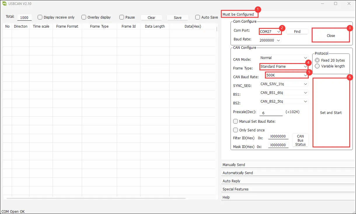
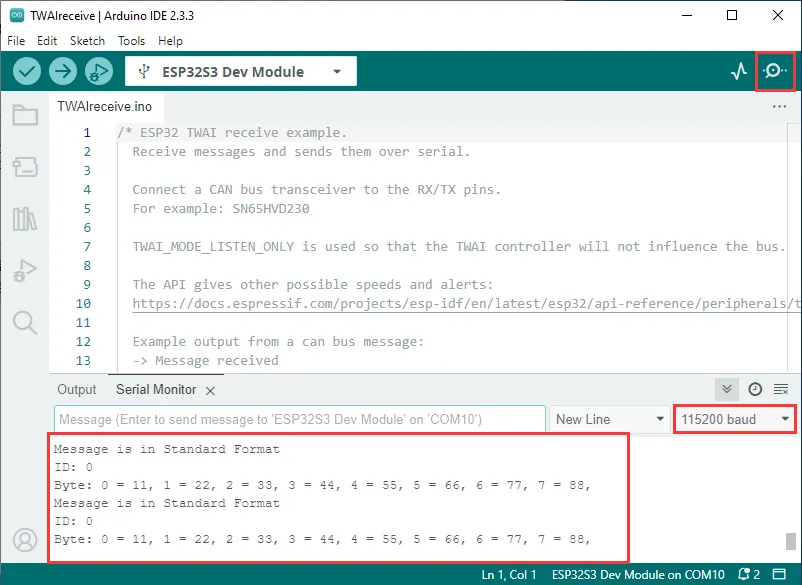
The ESP32-S3-Touch-LCD-4.3 waits for messages sent by the USB-CAN-A_TOOL. If received successfully, it prints them to the serial port.
08_DrawColorBar
This example tests the RGB screen: initializes the LCD and displays a color bar / test pattern.
Hardware Connection
- Connect the board to the computer using a USB cable
Code Analysis
waveshare_lcd_init():- First, it prints "Initialize IO expander" indicating the start of I/O expander initialization. It creates an
ESP_IOExpander_CH422Ginstance, initializes it, and starts its operation. It sets IO0 - IO7 pins to output mode, sets the touch screen reset pin (TP_RST) and LCD reset pin (LCD_RST) high, and turns off the LCD backlight (LCD_BL), then waits for 100 milliseconds. - Next, it prints "Create RGB LCD bus", creates an RGB panel bus object
ESP_PanelBus_RGB, configures its pins, width, height, RGB timing frequency and timing parameters, sets the bounce buffer size and display active-low flag, then starts the panel bus operation. - Then, it prints "Create LCD device", creates an LCD object
ESP_PanelLcd, passes the panel bus object, color bit depth, and reset pin as parameters, and performs initialization, reset, and start operations. IfEXAMPLE_ENABLE_PRINT_LCD_FPSis defined, it attaches the VSync end callback function to the LCD object. - Finally, it prints "Draw color bar from top left to bottom right, the order is B - G - R", calls the
colorBarTestfunction to draw a color bar on the LCD, and turns on the LCD backlight.
- First, it prints "Initialize IO expander" indicating the start of I/O expander initialization. It creates an
Example Flashing
- Select the board model ESP32S3 Dev Module and the port
- Set the board parameters
- Flash the demo
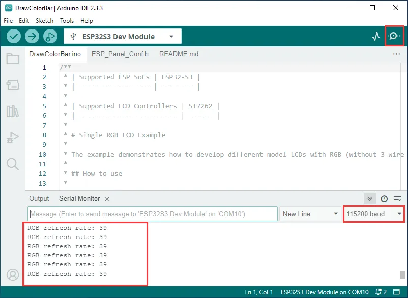
Operation Result
- Logs are printed to the serial port, and the screen lights up.

09_lvgl_Porting
This example tests LVGL porting: initializes ESP32_Display_Panel + LVGL and runs an LVGL Demo.
Hardware Connection
- Connect the board to the computer using a USB cable
Code Analysis
-
setup():- Initializes serial communication at a baud rate of 115200. It then creates and initializes the I/O expander, sets pin modes and states, and initializes the GT911 touch screen. Next, it creates and initializes the panel device, configuring the RGB bus as needed. After that, it initializes LVGL, creates a simple label or optionally calls an LVGL example or demonstration function, and finally releases the mutex.
-
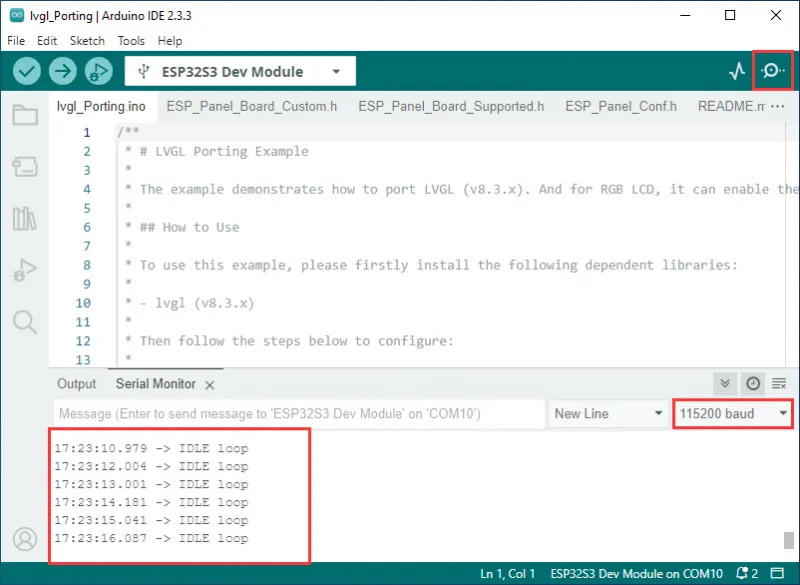
loop():- Only prints "IDLE loop" and waits for 1 second, with no other substantive operations. The overall purpose is to set up a user interface environment based on LVGL.
Code Modification
In ESP_Panel_Board_Custom.h, there is a macro definition to choose whether to enable touch functionality. A value of 0 corresponds to touch disabled, a value of 1 corresponds to touch enabled. Choose based on the purchased model.
#define ESP_OPEN_TOUCH 0 // 1 initiates the touch, 0 closes the touch.
Example Flashing
- Select the board model ESP32S3 Dev Module and the port
- Set the board parameters
- Flash the demo
Operation Result
-
The serial port prints the screen refresh rate, and the screen lights up.