Working with ESP-IDF
This chapter includes the following sections:
- ESP-IDF Getting Started
- Setting Up Development Environment (Windows)
- Common Example Descriptions (Brief Overview and Code Explanation)
ESP-IDF Getting Started
New to ESP32 ESP-IDF development and looking to get started quickly? We have prepared a general Getting Started Tutorial for you.
- Section 1: Environment Setup
- Section 2: Running Examples
- Section 3: Creating a Project
- Section 4: Using Components
- Section 5: Debugging
- Section 6: FreeRTOS
- Section 7: Peripherals
- Section 8: Wi-Fi Programming
- Section 9: BLE Programming
Please Note: This tutorial uses the ESP32-S3-Zero as a teaching example, and all hardware code is based on its pinout. Before you start, it is recommended that you check the pinout of your development board to ensure the pin configuration is correct.
Setting Up Development Environment
The following guide uses Windows as an example, demonstrating development using VS Code + the ESP-IDF extension. macOS and Linux users should refer to the official documentation.
The screenshots in this section use ESP-IDF V5.5.2 as an example. When installing, please select the ESP-IDF version that matches your board's example.
Install the ESP-IDF Development Environment
-
Download the installation manager from the ESP-IDF Installation Manager page. This is Espressif's latest cross-platform installer. The following steps demonstrate how to use its offline installation feature.
Click the Offline Installer tab on the page, then select Windows as the operating system and the ESP-IDF version you need (the version shown in the screenshot is for reference only — choose the version that fits your actual needs).

After confirming your selection, click the download button. The browser will automatically download two files: the ESP-IDF Offline Package (.zst) and the ESP-IDF Installer (.exe).

Please wait for both files to finish downloading.
-
Once the download is complete, double-click to run the ESP-IDF Installer (eim-gui-windows-x64.exe).
The installer will automatically detect if the offline package exists in the same directory. Click Install from archive.

Next, select the installation path. We recommend using the default path. If you need to customize it, ensure the path does not contain Chinese characters or spaces. Click Start installation to proceed.

-
When you see the following screen, the ESP-IDF installation is successful.

-
We recommend installing the drivers as well. Click Finish installation, then select Install driver.

Install Visual Studio Code and the ESP-IDF Extension
-
Download and install Visual Studio Code.
-
During installation, it is recommended to check Add "Open with Code" action to Windows Explorer file context menu to facilitate opening project folders quickly.
-
In VS Code, click the Extensions icon
 in the Activity Bar on the side (or use the shortcut Ctrl + Shift + X) to open the Extensions view.
 -
Enter ESP-IDF in the search box, locate the ESP-IDF extension, and click Install.

-
For ESP-IDF extension versions ≥ 2.0, the extension will automatically detect and recognize the ESP-IDF environment installed in the previous steps, requiring no manual configuration.
Flashing Demo
-
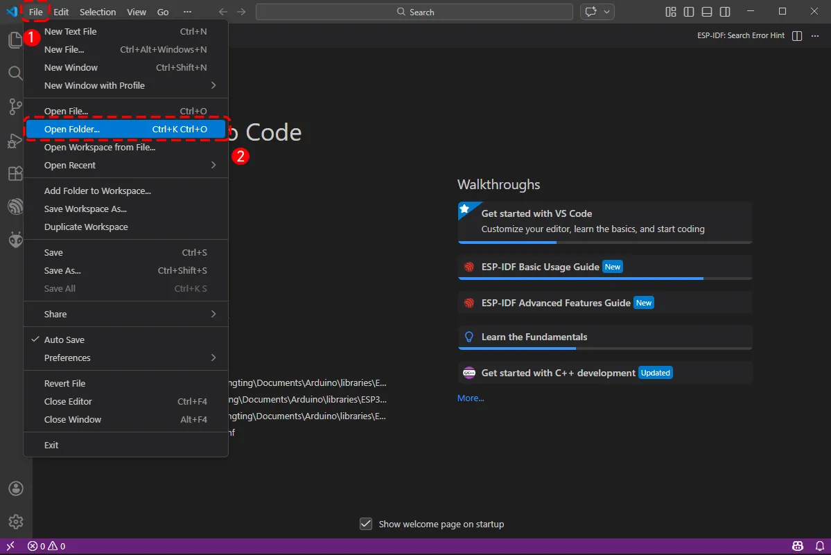
After installing the ESP-IDF development environment, select the folder to open the example.
-
In the pop-up window, select the example under the ESP-IDF directory within the extracted example package, and click to select a file (here, the
01_I2C_Testfolder is used as an example).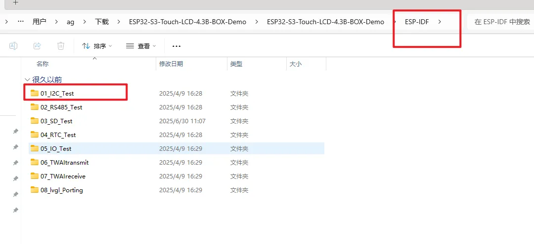
-
To upload the corresponding code to the ESP32-S3, connect the USB port of the ESP32-S3-Touch-LCD-4.3B to a USB port on your computer using a Type-C to Type-A cable.
-
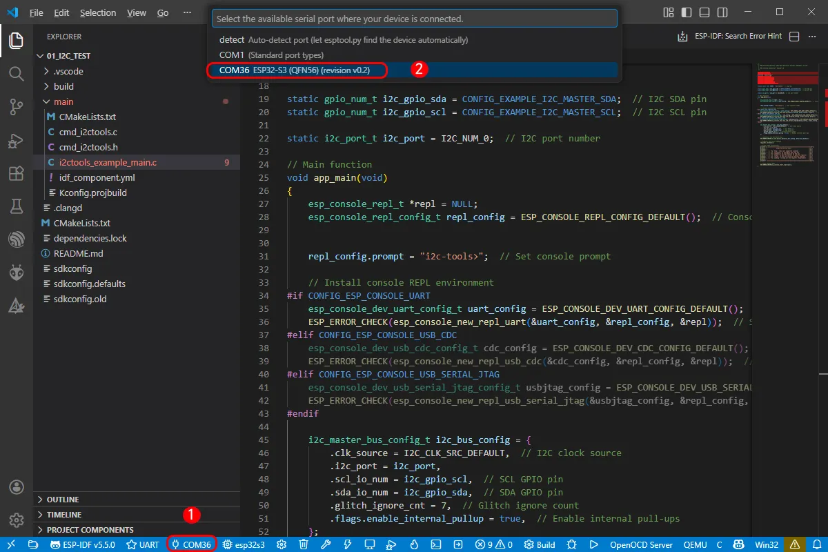
If this is the first time flashing a new project, you need to select the detected COM port. For example, here it is detected as COM36.
-
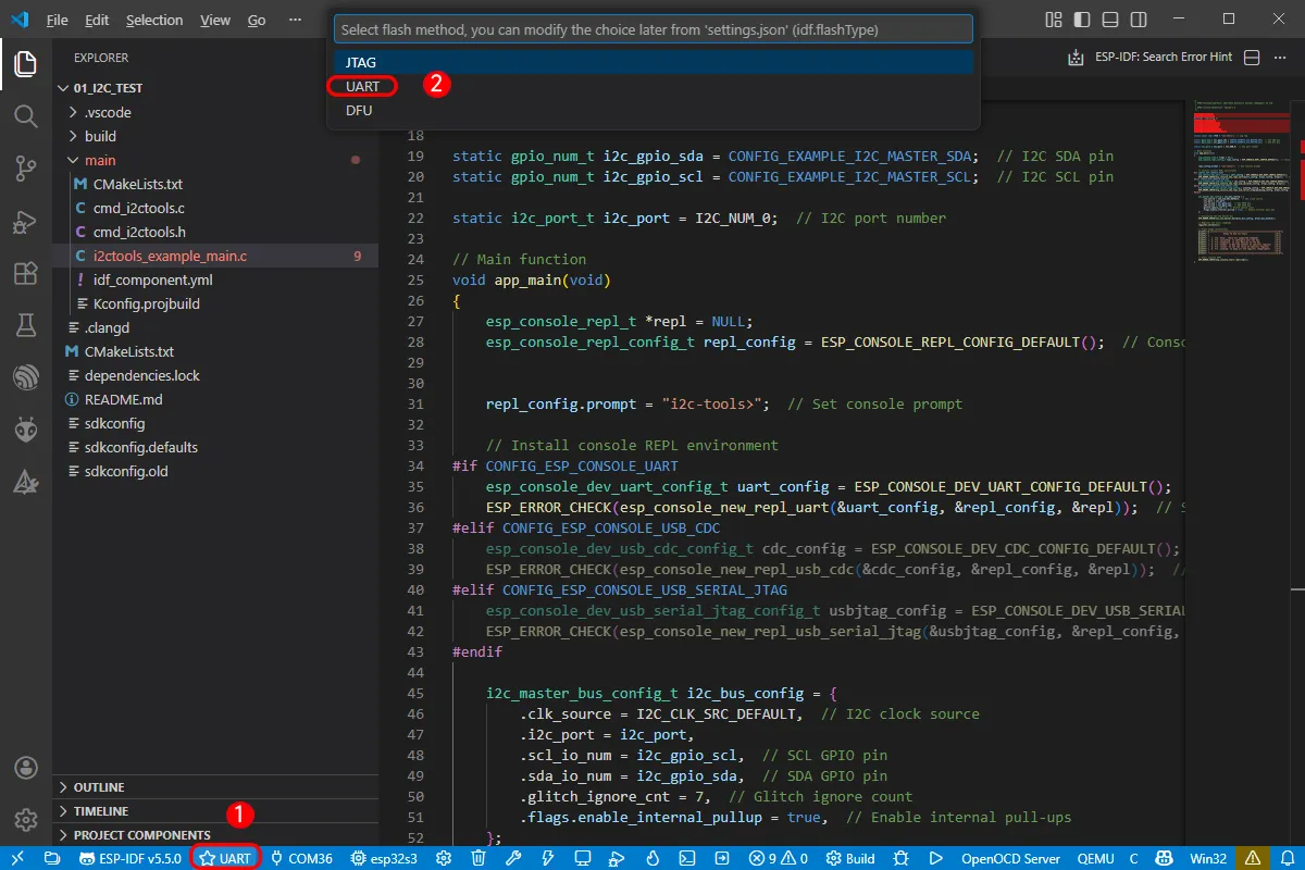
Select the download method: UART.
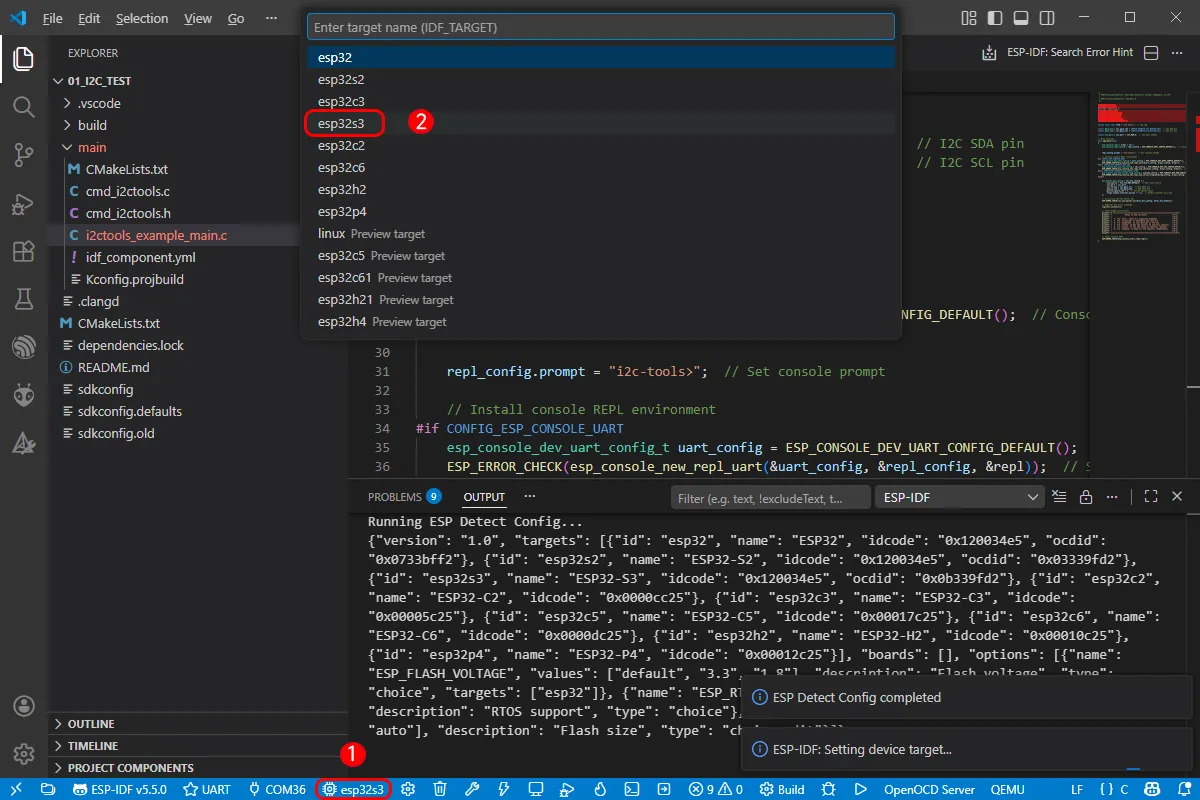
-
Next, select the main chip as ESP32S3.
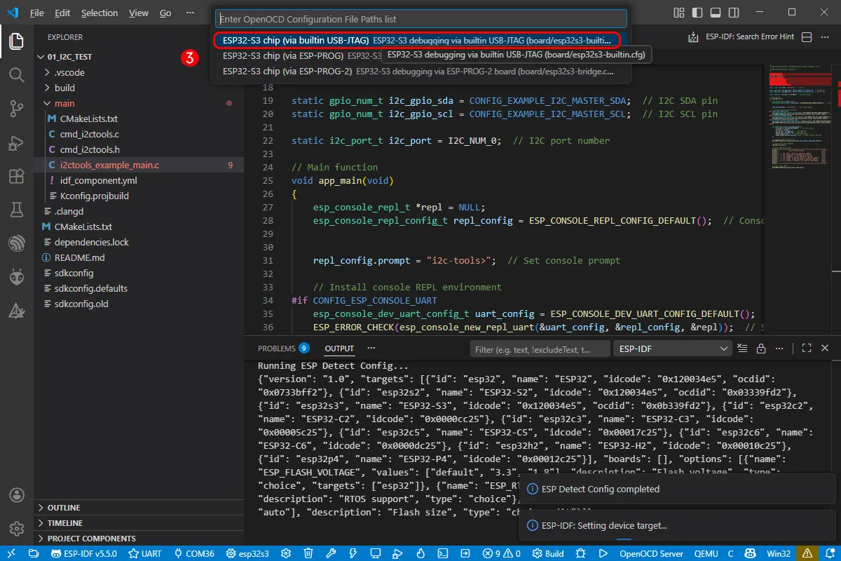
Select the path for openocd. This does not affect our process, so we can choose any option. Here, select the first one.
-
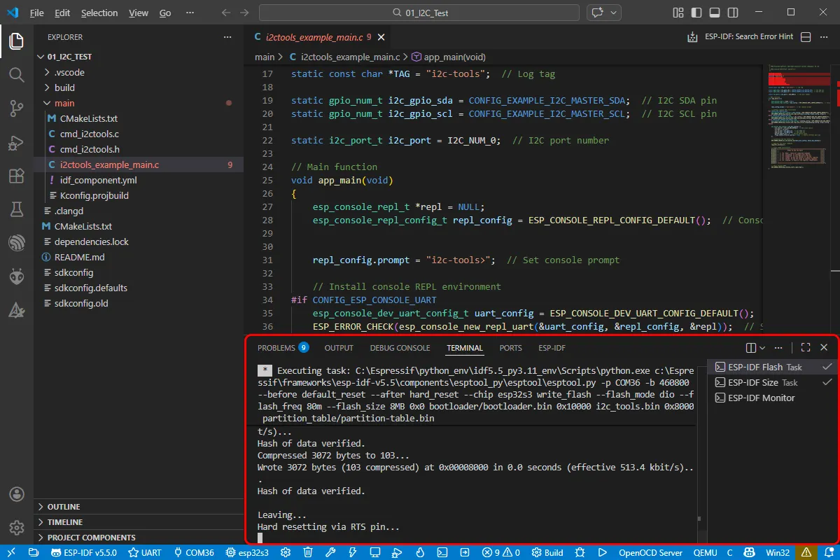
Click the following "little flame" (Build Flash Monitor) one-click button to execute Build --> Flash --> Monitor sequentially.
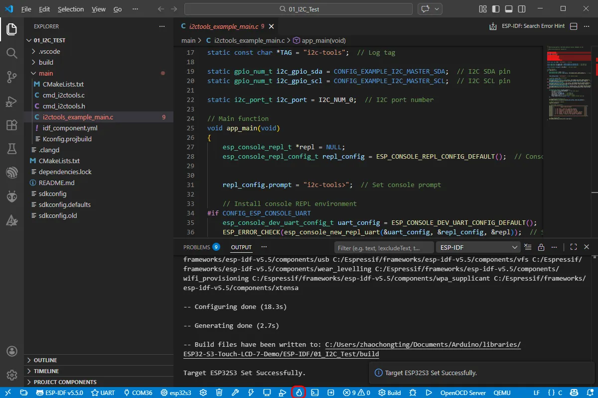
-
The board has a built-in automatic download circuit, so no manual operation is required for automatic downloading. Then wait for the compilation and flashing to complete. The first compilation may take a while.
Example
The Arduino examples are located in the example package.
Below are the purpose, key points, and operational effects for each example (for quick start).
| Demo | Basic Description |
|---|---|
| 01_I2C_Test | Test I2C header |
| 02_RS485_Test | Test RS485 header |
| 03_SD_Test | Test TF card slot |
| 04_RTC_Test | Test RTC clock and RTC interrupt |
| 05_IO_Test | Test isolated I/O |
| 06_TWAItransmit | Test CAN header |
| 07_TWAIreceive | Test CAN header |
| 08_lvgl_Porting | Port LVGL |
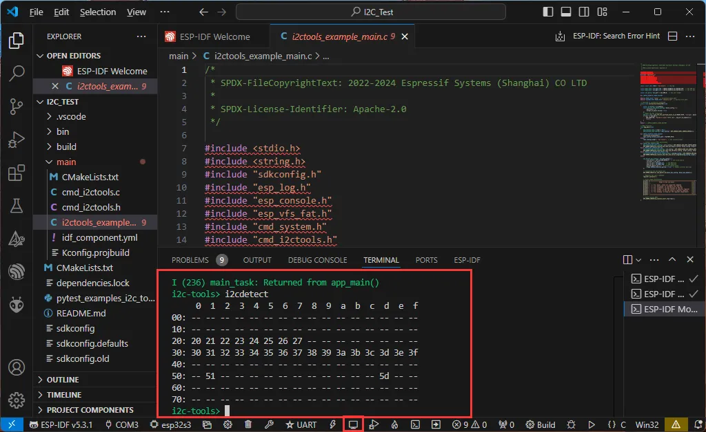
01_I2C_Test
This example demonstrates how to scan for devices on the I2C bus via the I2C interface, verifying the communication status of the I2C connector and onboard I2C devices.
Hardware Connection
- Connect the board to the computer using a USB cable
- An external I2C device can be connected to the I2C connector (optional)
Code Analysis
app_main(): Example entry point, configures the serial console and I2C master bus.esp_console_new_repl_*(): Creates a REPL environment based on configuration options (UART / USB_CDC / USB_SERIAL_JTAG) as the command line interface.i2c_new_master_bus(): Initializes the I2C master bus with the specified SDA/SCL pins and clock parameters.register_i2ctools(): Registers I2C tool commands such asi2cdetect,i2cget,i2csetfor convenient I2C device operation via the serial console.esp_console_start_repl(): Starts the command line loop, waiting for user input and executing commands.
Operation Result
- The serial debug assistant prints the scanned I2C device addresses every 5 seconds.
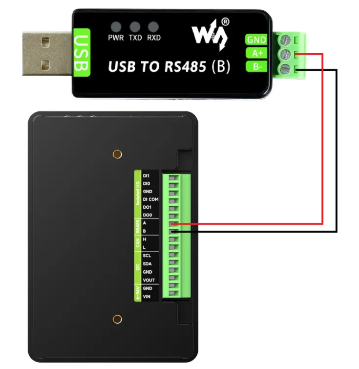
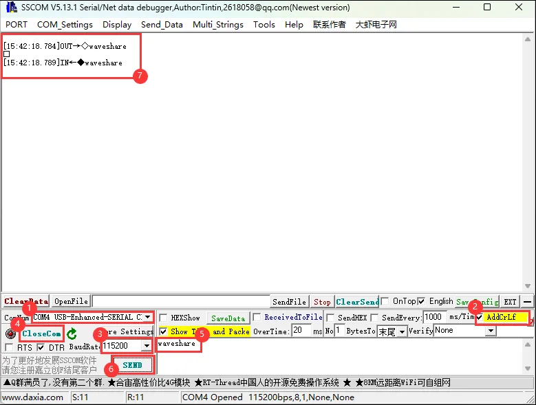
02_RS485_Test
This example demonstrates how to use the ESP32-S3's hardware serial port for RS485 data transmission and reception.
Hardware Connection
-
Connect the board to the computer using a USB cable
-
Connect the A/B terminals of the RS485 connector to an external RS485 device
Code Analysis
app_main(): Example entry point, creates theecho_taskand starts the serial loopback test.echo_task(): Continuously receives and transmits data in a loop, implementing the RS485 loopback function.uart_driver_install(): Installs the UART driver and allocates a receive buffer.uart_param_config(): Configures UART parameters such as baud rate, data bits, parity, etc.uart_set_pin(): Binds TX/RX pins to the corresponding RS485 interface pins.uart_read_bytes()/uart_write_bytes(): Reads data from the UART receive buffer (blocking) and writes the same data back, implementing data echo.
Operation Result
- Data sent from an external RS485 terminal is echoed back by the board.
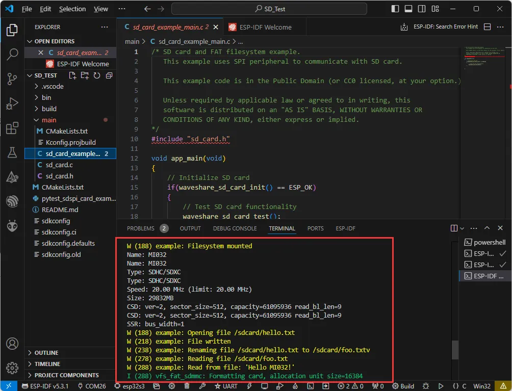
03_SD_Test
This example demonstrates TF card mounting and file system access.
Hardware Connection
- Connect the board to the computer using a USB cable
- Insert a TF/SD card
Code Analysis
app_main(): Example entry point, manages the overall TF card initialization and test flow.waveshare_sd_card_init(): Wraps low-level interfaces likeesp_vfs_fat_sdmmc_mount()to complete SDMMC host configuration and file system mounting.waveshare_sd_card_test(): Performs read/write tests after successful mounting, such as creating a file, writing data, and reading it back to verify TF card functionality.
Operation Result
-
Serial output displays successful mounting information and TF card parameters like capacity.
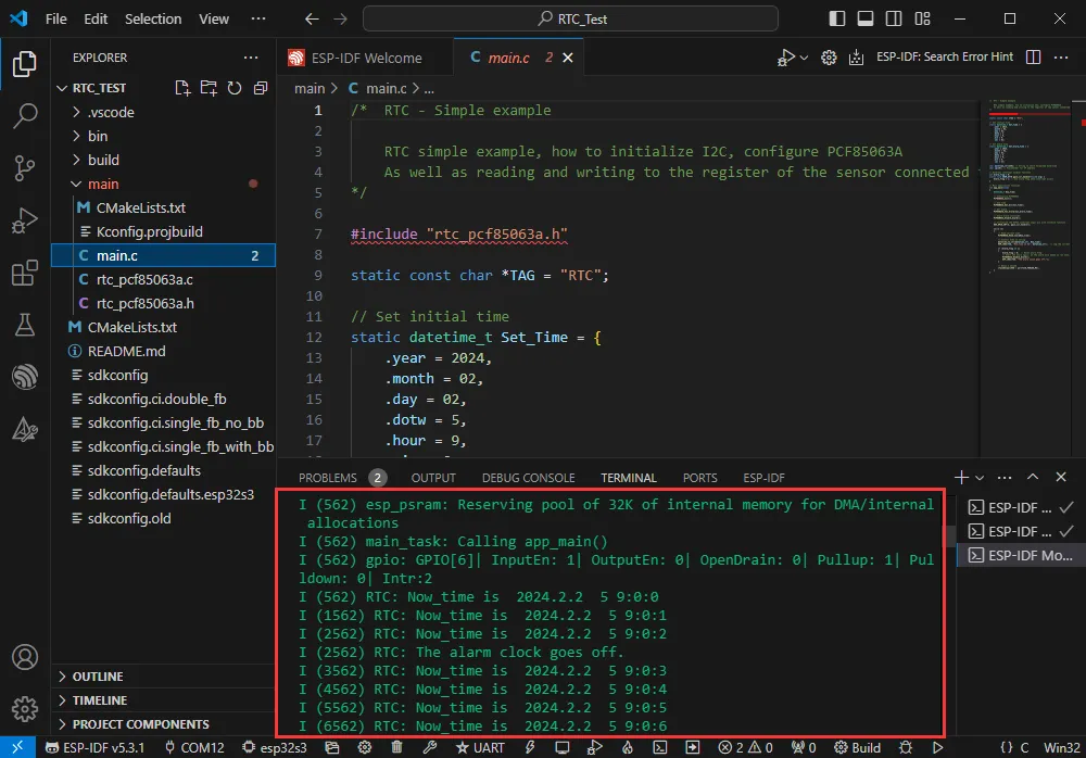
04_RTC_Test
This example demonstrates time read/write and alarm interrupt functionality for the onboard PCF85063 RTC.
Hardware Connection
- Connect the board to the computer using a USB cable
Code Analysis
Set_Time/Set_Alarm_Time: Defines the initial time and alarm trigger time for the RTC after power-up.PCF85063A_Init(): Initializes the PCF85063A, configuring I2C communication parameters.PCF85063A_Set_All(): WritesSet_Timeto the RTC registers to set the current time.PCF85063A_Set_Alarm(): Configures the alarm time and writes it to the corresponding RTC registers.PCF85063A_Enable_Alarm(): Enables the alarm interrupt output.DEV_GPIO_INT(): Configures a specific GPIO pin as an interrupt input and binds agpio_isr_handlercallback to receive RTC interrupt signals.PCF85063A_Read_now(): Periodically reads the current time, converting it to a string viadatetime_to_str()and printing it to the log.
Operation Result
-
The serial port periodically outputs the current time and prints a notification when the alarm triggers.
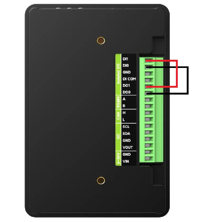
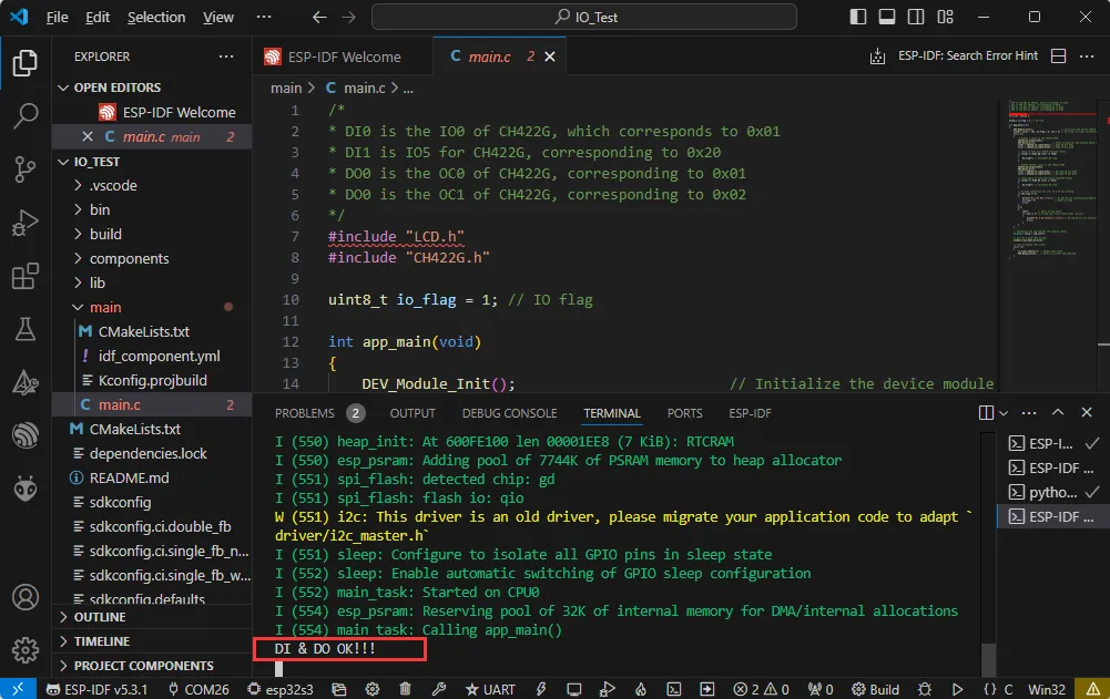
05_IO_Test
This example verifies the isolation I/O functionality.
Hardware Connection
- Connect the board to the computer using a USB cable;
- Connect the DO/DI pins as described in the example to test the isolation function.
Code Analysis
DEV_Module_Init(): Initializes onboard peripherals and the CH422G expander chip, preparing for subsequent DI/DO tests.CH422G_od_output(): Outputs different values to the OC pins of the CH422G, driving level changes on the isolated DO pins.CH422G_io_input(): Reads the IO state of the CH422G to check if the isolated DI pins follow expected changes.DI_flag/num: Counts successes and failures; if multiple checks fail, it determines the DI/DO is abnormal.LCD_init(): Initializes the RGB LCD display and returns a pointer to the LVGL display object.example_lvgl_demo_ui(): Runs a simple LVGL interface after the test completes, allowing observation of test status or prompts on the screen.lv_timer_handler(): Called periodically in the loop to drive LVGL refresh and animations.
Operation Result
-
The serial port prints DI status and observes level changes on the DO port.
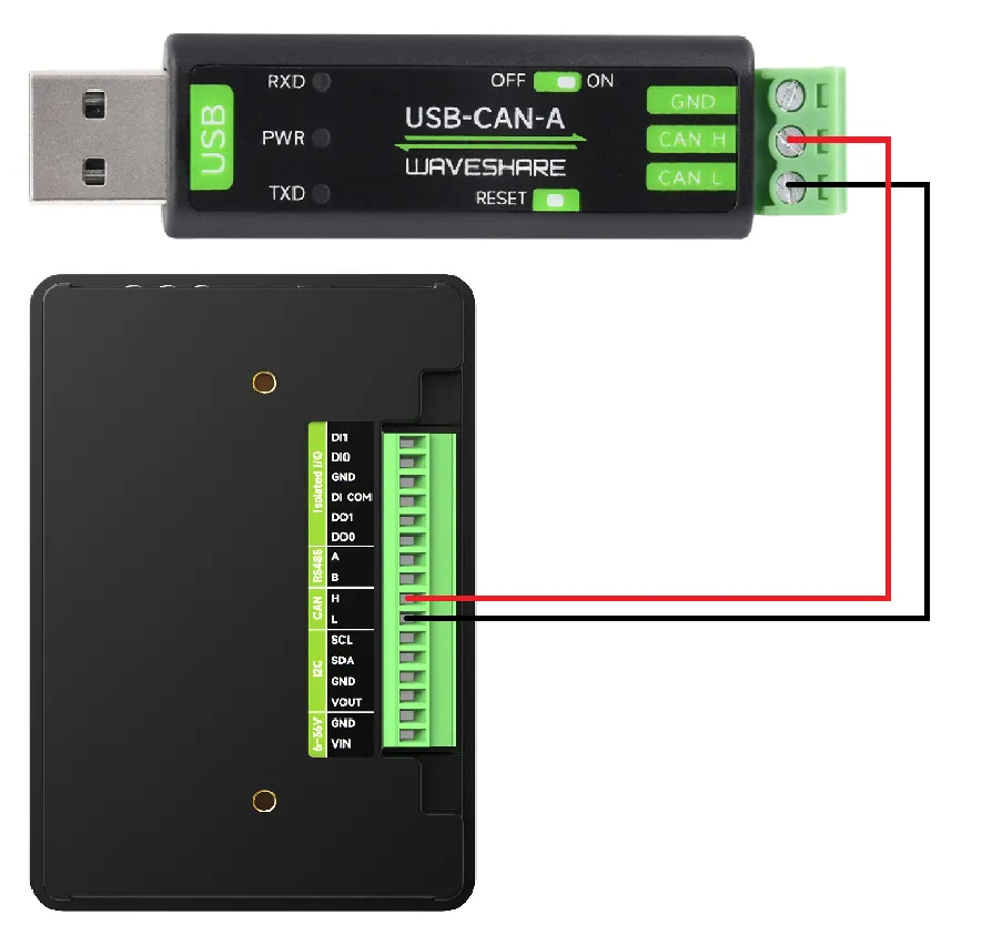
06_TWAItransmit
This example demonstrates how to send data using the ESP32-S3's TWAI (CAN-compatible) interface.
Hardware Connection
-
Connect the board to the computer using a USB cable
-
Connect the CAN interface (CANH, CANL) to a CAN bus
Code Analysis
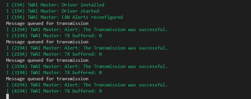
app_main(): Example entry point, loops to call the TWAI transmit interface.waveshare_twai_init(): Configures CAN-related GPIO and TWAI peripherals, performing low-level initialization liketwai_driver_install()and enabling the CAN channel via the expander IO.waveshare_twai_transmit(): Constructs CAN frames with a fixed ID and data payload, transmitting them periodically at a set interval for debugging with other nodes.
Operation Result
-
Another CAN node can receive messages with ID 0x123.
07_TWAIreceive
This example demonstrates how to receive data using the ESP32-S3's TWAI (CAN-compatible) interface.
Hardware Connection
-
Connect the board to the computer using a USB cable
-
Connect the CAN interface (CANH, CANL) to a CAN bus
Code Analysis
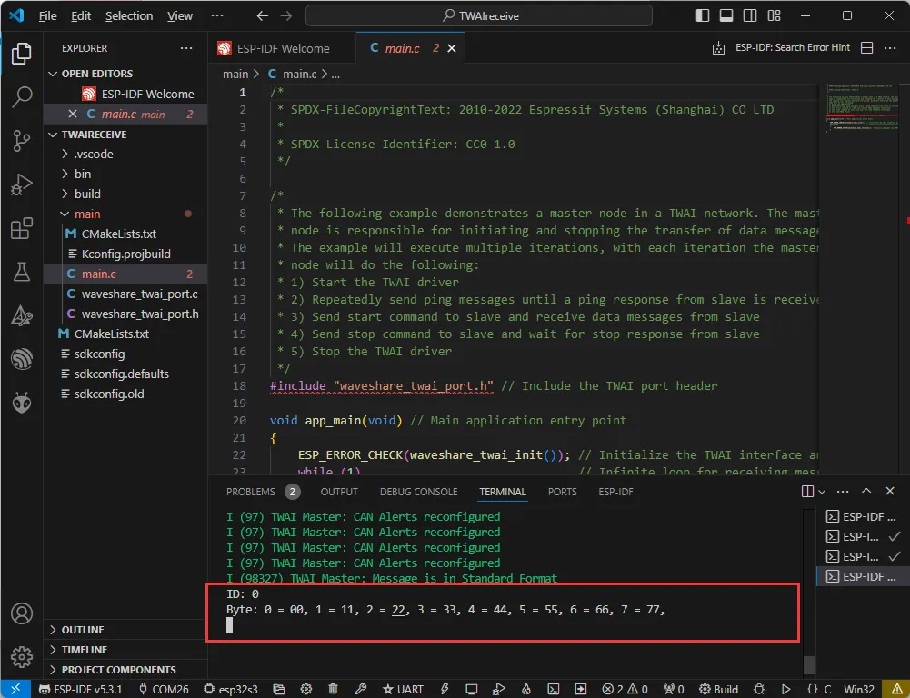
app_main(): Example entry point, initializes the TWAI interface and enters an infinite loop to receive data.waveshare_twai_init(): Same as the transmit example, completes CAN pin and TWAI peripheral parameter configuration.waveshare_twai_receive(): Internally calls APIs liketwai_receive(), reading messages from the receive queue; upon receiving data, it parses the ID and data payload and prints them to the serial port.
Operation Result
-
The serial port prints the ID and data of received CAN messages.
08_lvgl_Porting
This example demonstrates the porting of the LVGL graphics library and basic display functionality.
Hardware Connection
- Connect the board to the computer using a USB cable;
- The touch screen can be used for interaction.
Code Analysis
app_main(): Example entry point, responsible for the overall initialization flow of the RGB LCD and LVGL.waveshare_esp32_s3_rgb_lcd_init(): Encapsulates the initialization of clocks, RGB interface, backlight, and the LVGL display driver.lvgl_port_lock()/lvgl_port_unlock(): Acquires and releases the LVGL mutex, ensuring safe LVGL API calls in a single-task environment.lv_demo_widgets()/lv_demo_music(): Runs official LVGL demos based on configuration, used to demonstrate basic widgets, animations, and touch interaction effects.
Operation Result
-
The screen displays the LVGL demo interface, supporting touch interaction.
