ESP32-S3-Touch-LCD-5
- ESP32-S3-LCD-5 (Without Touch Function)
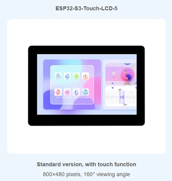
- ESP32-S3-Touch-LCD-5 (With Touch Function)
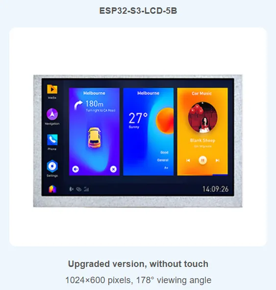
- ESP32-S3-LCD-5B (Without Touch Function)
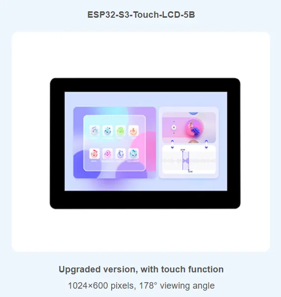
- ESP32-S3-Touch-LCD-5B (With Touch Function)
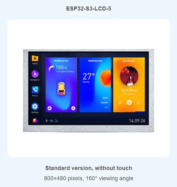
The ESP32-S3-Touch-LCD-5 is a low-cost, high-performance microcontroller development board designed by Waveshare. It supports 2.4GHz Wi-Fi and BLE 5, integrates large-capacity Flash and PSRAM, and features an onboard 5-inch wide capacitive touch LCD screen, enabling smooth operation of GUI applications such as LVGL. Combined with various peripheral interfaces (e.g., CAN, I2C, and RS485), it allows for rapid development of HMI applications based on the ESP32-S3. The rich functions and interfaces meet the power consumption requirements for application scenarios such as the Internet of Things (IoT), mobile devices, and smart homes.
| SKU | Product |
|---|---|
| 28117 | ESP32-S3-Touch-LCD-5 |
| 28151 | ESP32-S3-Touch-LCD-5B |
| 30321 | ESP32-S3-LCD-5 |
| 30320 | ESP32-S3-LCD-5B |
Specifications
| Basic Parameters | |
|---|---|
| Processor | High-performance Xtensa 32-bit LX7 dual-core processor, up to 240 MHz |
| Wi-Fi/Bluetooth | Supports 2.4 GHz Wi-Fi (802.11 b/g/n) and Bluetooth 5 (LE), onboard antenna |
| Embedded Memory | 512KB SRAM and 384KB ROM |
| Flash | 16MB Flash |
| PSRAM | 8MB PSRAM |
| Power Supply Range | Type-C 5V / DC 7-36V |
| Screen Parameters | |
| Resolution | 800 × 480 or 1024 × 600 |
| Display Colors | 65K colors |
| Display Interface | RGB |
| Display Panel | IPS |
| Viewing Angle | 160° |
| Brightness | 550 cd/m² |
| Touch Type | Capacitive |
| Touch Panel | Tempered Glass |
| Touch Features | Supports I2C interface control for capacitive touch, 5-point touch, interrupt support |
| Peripheral Interfaces | |
| Communication Interfaces | CAN, RS485, I2C, USB |
| Digital Input | 5~36V, bidirectional optocoupler isolation, supports dry contact and wet contact (NPN or PNP) switch inputs |
| Digital Output | 5~36V, optocoupler isolation, output uses high-current transistor, sink current up to 450mA |
| USB | Integrated full-speed USB |
| Others | |
| Power Consumption | 5V 450mA |
| Operating Temperature | 0℃ ~ 65℃ |
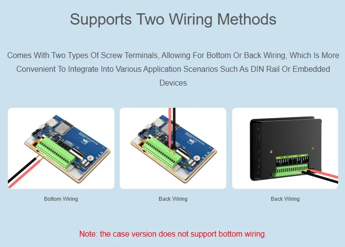
| Dimensions (L×W) | Standard Version: 112.4×75.1mm With Case Version: 116.3×79mm |
Features
- Powered by a high-performance Xtensa 32-bit LX7 dual-core processor, with a main frequency of up to 240MHz
- Supports 2.4 GHz Wi-Fi (802.11 b/g/n) and Bluetooth 5 (LE) with an onboard antenna
- Built-in 512KB SRAM and 384KB ROM, stacked with 16MB Flash and 8MB PSRAM
- Onboard 5inch wide capacitive touch screen, 800 × 480 or 1024 × 600 resolution, 65K colors
- Supports I2C interface control for capacitive touch, with 5-point touch, and supports interrupts
- Onboard CAN, RS485, I2C interfaces, TF card slot, and integrated full-speed USB
- Supports precise control features like flexible clocking and independent module power supply settings, enabling low-power modes for multiple scenarios
Precautions
- Automatic download circuit: The development board features an automatic download circuit. The Type-C port labeled UART is used for program download and log printing. After downloading the program, press the RESET button to run it.
- Antenna area: Pay attention to the PCB antenna area during use, avoiding other metal or plastic parts from touching the antenna location to avoid affecting wireless signals.
- TF card communication: The TF card can use SPI/MMC communication. Note that the SD_CS pin must be driven by EXIO4 of the CH422G.
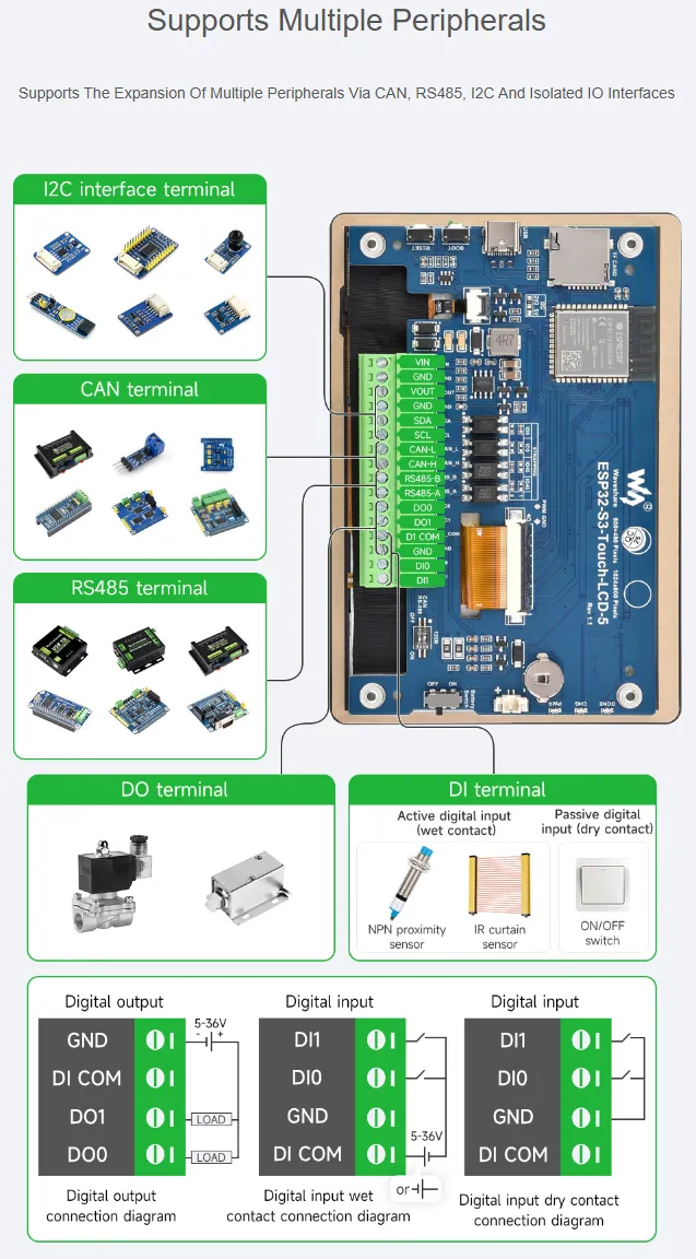
- Peripheral interfaces: The development board uses 3.5 mm terminal blocks to bring out peripheral pins such as CAN, I2C, RS485, and isolated I/O, facilitating on-site wiring.
- Termination resistors: CAN and RS485 peripherals are not connected to 120Ω termination resistors via a switch by default. Optionally turn the switch ON to enable termination resistor connection.
- I/O expansion: Since the 5inch screen occupies most GPIOs, the development board uses the CH422G chip to expand IOs for reset, backlight control, and other functions.
- BOOT mode: If the computer cannot recognize the port, try entering BOOT mode (hold the BOOT button while connecting to the computer, then release the BOOT button).
- Battery notes: The MX1.25 lithium battery connector supports only a single 3.7V lithium battery. Do not connect multiple battery packs simultaneously for charging/discharging. It is recommended to use a single cell with a capacity of ≤2000 mAh.
- I2C slave address conflicts: The onboard CH422G and touch controller occupy the following I2C addresses. Do not connect external devices with the same addresses:
- 0x20 - 0x27 (CH422G)
- 0x30 - 0x3F (CH422G)
- 0x5D (touch controller GT911)
Onboard Resources
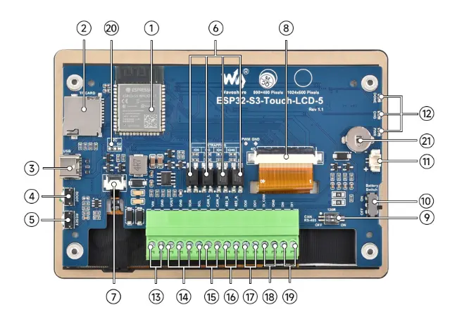
- ESP32-S3-WROOM-1-N16R8
Wi-Fi/Bluetooth SoC module, 240MHz operating frequency
Stacked 8MB PSRAM and 16MB Flash - TF Card Slot
For connecting TF cards - USB Type-C Port
For power supply and program flashing - BOOT Button
Press and hold while powering on for program flashing - RESET Button
Press to reset the ESP32S3 - Optocoupler Isolation
Isolates and protects I/O pins on the board - 5inch Screen Touch Connector
Connects the touch screen FPC - 5inch Screen Connector
Connects the LCD display FPC - CAN and RS485 Termination Resistor Switches
Balance resistor switches for the bus, disabled by default - Battery Connection Switch
ON: Connect battery
OFF: Disconnect battery - 3.7V Single-Cell Lithium Battery 1.25 Interface
MX1.25 interface, compatible with all 3.7V lithium batteries
- Status LEDs
DONE: Lithium battery charging complete indicator
CHG: Lithium battery charging indicator
PWR: Power indicator
(When power is connected, but no battery is connected or the switch is off, CHG flashes, DONE stays on) - 7-36V DC Power Supply
Wide voltage input interface, supports 7-36V DC power - I2C Interface
VOUT outputs 5V/3.3V (switchable via onboard resistor, select one) - CAN Interface
CAN 2.0 compliant - RS485 Terminal Block
Supports 485 bus communication - Digital Output
5~36V, open-drain output, output load 450mA/channel (MAX) - Input Signal Common Terminal
Not connected (floating): Dry contact (passive) input
Connected to power positive: Low-level trigger, NPN-type wet contact (active) input, voltage 5V-36V DC
Connected to power negative: High-level trigger, PNP-type wet contact (active) input, voltage 5V-36V DC - Digital Input
5~36V, dry contact / wet contact (NPN or PNP type) - VOUT Output Voltage
Used to set the supply voltage and I/O level for I2C devices, default 3.3V - RTC Battery Holder
Specification: CR927
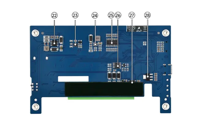
- CHARGE
Lithium battery charging management chip - PCF85063
RTC clock chip, provides accurate time control - AP3032KTR-G1
Screen backlight boost chip - CH422G
IO expander chip
- SP3485
RS485 transceiver chip - TJA1051T/3/1J
CAN interface chip - SGM2212-3.3
800mA low-noise LDO
Interface Description
When using the ESP32-S3-Touch-LCD-5, it is important to understand the hardware connections of the different peripherals.
LCD Interface: Connector for the LCD cable (click to expand)
| ESP32-S3 | LCD | Description |
|---|---|---|
| GPIO0 | G3 | Green data bit 3 |
| GPIO1 | R3 | Red data bit 3 |
| GPIO2 | R4 | Red data bit 4 |
| GPIO3 | VSYNC | Vertical sync signal |
| GPIO4 | TP_IRQ | Touch interrupt pin |
| GPIO5 | DE | Data enable signal |
| GPIO7 | PCLK | Pixel clock signal |
| GPIO8 | TP_SDA | Touch data pin (I2C) |
| GPIO9 | TP_SCL | Touch clock pin (I2C) |
| GPIO10 | B7 | Blue data bit 7 |
| GPIO14 | B3 | Blue data bit 3 |
| GPIO17 | B6 | Blue data bit 6 |
| GPIO18 | B5 | Blue data bit 5 |
| GPIO21 | G7 | Green data bit 7 |
| GPIO38 | B4 | Blue data bit 4 |
| GPIO39 | G2 | Green data bit 2 |
| GPIO40 | R7 | Red data bit 7 |
| GPIO41 | R6 | Red data bit 6 |
| GPIO42 | R5 | Red data bit 5 |
| GPIO45 | G4 | Green data bit 4 |
| GPIO46 | HSYNC | Horizontal sync signal |
| GPIO47 | G6 | Green data bit 6 |
| GPIO48 | G5 | Green data bit 5 |
| CH422G | LCD | - |
| EXIO1 | TP_RST | Touch reset pin |
| EXIO2 | DISP | Backlight enable pin |
| EXIO3 | LCD_RST | Screen reset pin |
USB Interface: Used for power supply and flashing (click to expand)
| ESP32-S3 | USB | Description |
|---|---|---|
| GPIO19 | USB_DN | Data line D- |
| GPIO20 | USB_DP | Data line D+ |
TF Card Interface: Connector for TF card (click to expand)
| ESP32-S3 | TF | Description |
|---|---|---|
| GPIO11 | MOSI | TF card input pin |
| GPIO12 | SCK | TF card clock pin |
| GPIO13 | MISO | TF card output pin |
| CH422G | TF | - |
| EXIO4 | SD_CS | TF card enable pin, active low |
RS485 Interface: Onboard RS485 interface for direct device communication; transmission/reception mode is switched automatically (click to expand)
| ESP32-S3 | RS485 | Description |
|---|---|---|
| GPIO43 | RS485_RXD | Data input |
| GPIO44 | RS485_TXD | Data output |
CAN Interface: Enables transmission/reception control, data analysis, acquisition, and monitoring for CAN bus networks (click to expand)
| ESP32-S3 | CAN | Description |
|---|---|---|
| GPIO15 | CANTX | Data output |
| GPIO16 | CANRX | Data input |
RTC Interface: Onboard PCF85063 provides clock and calendar information (click to expand)
| ESP32-S3 | RTC | Description |
|---|---|---|
| GPIO8 | RTC_SDA | RTC Data Pin |
| GPIO9 | RTC_SCL | RTC Clock Pin |
I2C Interface: Connects to the I/O expander chip, touch interface, and external interfaces (click to expand)
| ESP32-S3 | I2C | Description |
|---|---|---|
| GPIO8 | SDA | I2C data pin |
| GPIO9 | SCL | I2C clock pin |
Isolated I/O Interface: Isolated I/O consists of digital output, digital input, and input signal common terminal. I/O level can reach 5~36V (click to expand)
| CH422G | DI/DO | Description |
|---|---|---|
| EXIO0 | DI0 | Digital Input 0 |
| EXIO5 | DI1 | Digital Input 1 |
| OD0 | DO0 | Digital Output 0 |
| OD1 | DO1 | Digital Output 1 |
- MX1.25 Battery Interface: The development board uses the efficient charging/discharging management chip CS8501, which can boost a single-cell lithium battery to 5V. The current charging current is 580mA. Users can change the charging current by replacing resistor R45. For details, please refer to the ESP32-S3-Touch-LCD-5 Schematic.
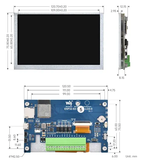
Dimensions
-
Dimensions for the version without touch screen:
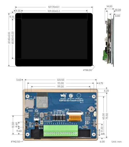
-
Dimensions for the version with touch screen:
Development Methods
The ESP32-S3-Touch-LCD-5 supports two development frameworks: Arduino IDE and ESP-IDF, providing developers with flexible choices. You can select the appropriate development tool based on project requirements and personal preference.
Both development methods have their own advantages. Developers can choose based on their needs and skill levels. Arduino is simple to learn and quick to start, suitable for beginners and non-professionals. ESP-IDF provides more advanced development tools and stronger control capabilities, suitable for developers with professional backgrounds or higher performance requirements, and is more appropriate for complex project development.
-
Arduino IDE is a convenient, flexible, and easy-to-use open-source electronics prototyping platform. It requires minimal foundational knowledge, allowing for rapid development after a short learning period. Arduino has a huge global user community, providing a vast amount of open-source code, project examples, and tutorials, as well as a rich library ecosystem that encapsulates complex functions, enabling developers to implement various features rapidly. You can refer to the Working with Arduino to complete the initial setup, and the tutorial also provides related demos for reference.
-
ESP-IDF, short for Espressif IoT Development Framework, is a professional development framework launched by Espressif Systems for its ESP series of chips. It is based on C language development and includes compilers, debuggers, flashing tools, etc. It supports development via command line or integrated development environments (such as Visual Studio Code with the Espressif IDF plugin), which provides features like code navigation, project management, and debugging. We recommend using VS Code for development. For the specific configuration process, please refer to the Working with ESP-IDF. The tutorial also provides relevant demos for reference.