ESP32-S3-Touch-LCD-7
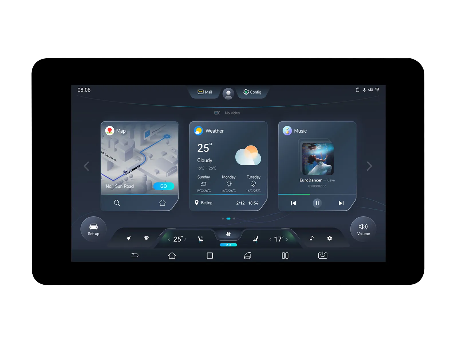
This is a low-cost, high-performance MCU development board designed by Waveshare. It supports 2.4 GHz Wi-Fi and BLE 5, integrates high-capacity Flash and PSRAM, and has a 7-inch wide capacitive touch LCD screen on board to smoothly run GUI interface programs such as LVGL. It combines a variety of peripheral interfaces (e.g., CAN, I2C, RS485, etc.) to quickly develop applications such as HMIs for ESP32-S3. The rich functions and interfaces meet the power consumption requirements for application scenarios such as the Internet of Things (IoT), mobile devices, and smart homes.
| SKU | Product |
|---|---|
| 27078 | ESP32-S3-Touch-LCD-7 |
| 30406 | ESP32-S3-LCD-7 |
Features
- Powered by a high-performance Xtensa 32-bit LX7 dual-core processor, with a main frequency of up to 240 MHz
- Supports 2.4 GHz Wi-Fi (802.11 b/g/n) and Bluetooth 5 (LE) with an onboard antenna
- Built-in 512 KB SRAM and 384 KB ROM, stacked with 16 MB Flash and 8 MB PSRAM (or 8 MB Flash and 8 MB PSRAM)
- Onboard 7-inch LCD screen with 800 × 480 resolution, 65K colors
- Supports I2C interface control for capacitive touch (optional), 5-point touch, interrupt support
- Onboard CAN, RS485, I2C interfaces, TF card slot, and integrated full-speed USB
- Supports precise control features like flexible clocking and independent module power supply settings, enabling low-power modes for multiple scenarios
Version Options

Specifications
| Basic Parameters | |
|---|---|
| Processor | High-performance Xtensa 32-bit LX7 dual-core processor, main frequency up to 240 MHz |
| Wi-Fi / Bluetooth | Supports 2.4 GHz Wi-Fi (802.11 b/g/n) and Bluetooth 5 (LE), onboard antenna |
| Flash | 8 MB |
| PSRAM | 8 MB |
| Power Supply Range | Type-C 5 V |
| Screen Parameters | |
| Resolution | 800 × 480 |
| Display Interface | RGB |
| Display Panel | IPS |
| Viewing Angle | 170° |
| Screen Brightness | 345 cd/m² |
| Touch Type | Capacitive |
| Touch Panel | Tempered Glass |
| Peripheral Interfaces | |
| Communication Interfaces | CAN, RS485, I²C, USB |
| Others | |
| Power Consumption | 5 V 450 mA |
| Operating Temperature | 0 ℃ to 65 ℃ |
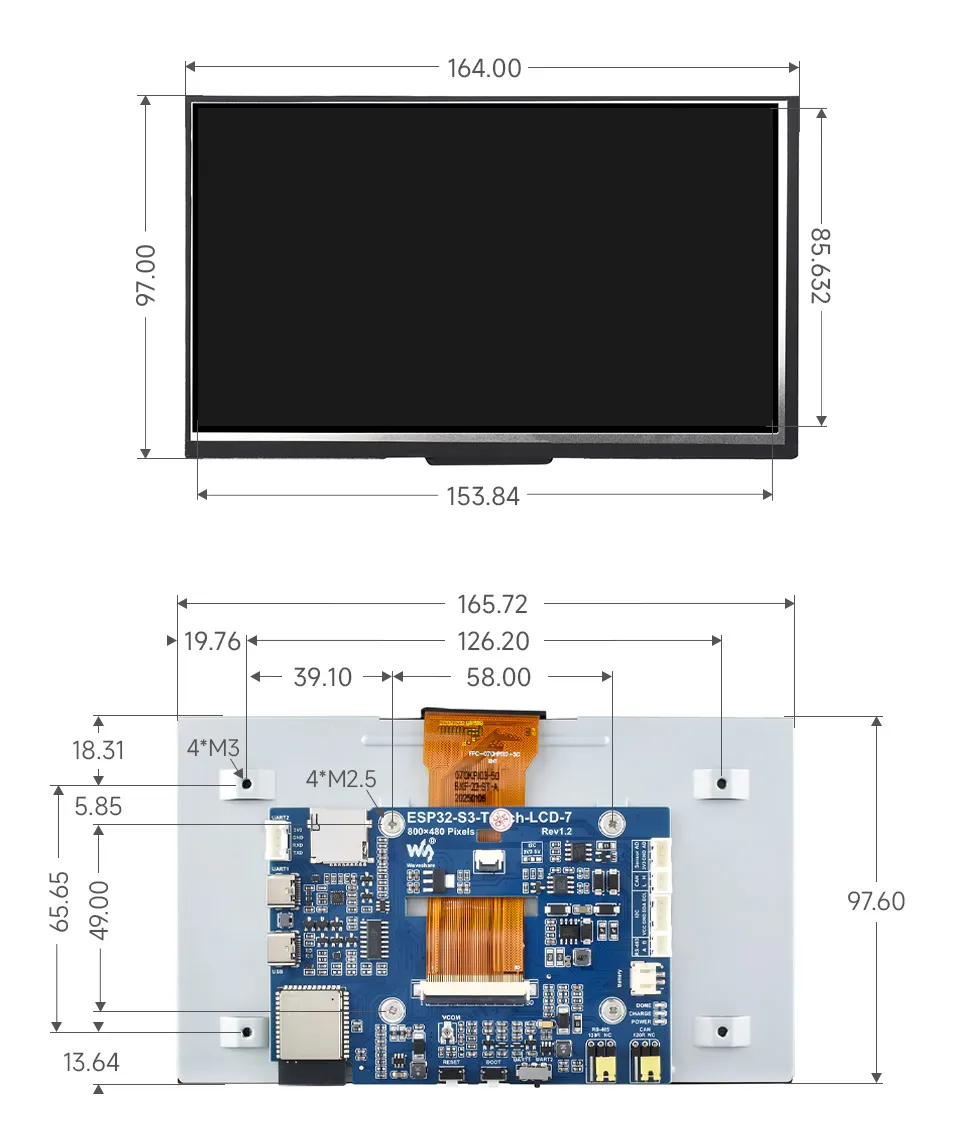
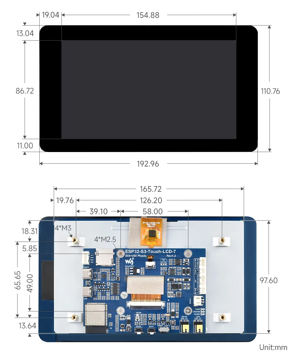
| Product Dimensions (L × W) | Without Touch Version: 164 × 97 mm; With Touch Version: 192.96 × 110.76 mm |
Onboard Resources
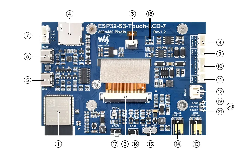
- ESP32-S3N16R8 Wi-Fi Bluetooth SoC module, 240 MHz operating frequency, stacked 16 MB Flash and 8 MB PSRAM
- 7-inch display panel connector
- Touch panel connector
- TF card slot
- USB Type-C port
- USB TO UART Type-C port UART1 Port
- UART2 connector 6 and 7 share the same UART, selected by switch 15
- Sensor header
- CAN header
- I2C header
- RS485 header
- 3.7V single lithium battery PH2.0 header PH2.0 connector
- CAN terminal resistor selection
- RS485 terminal resistor selection
- UART selection UART1 or UART2
- BOOT button Press and hold to enter programming mode
- RESET button Press to reset the controller
- I2C level selection 3.3V or 5V
- DONE Lithium battery charging completed indicator
- CHG Lithium battery charging indicator
- PWR Power supply indicator
Development Methods
The ESP32-S3-Touch-LCD-7 supports two development frameworks: Arduino IDE and ESP-IDF, providing developers with flexible choices. You can select the appropriate development tool based on project requirements and personal preference.
Both development methods have their own advantages. Developers can choose based on their needs and skill levels. Arduino is simple to learn and quick to start, suitable for beginners and non-professionals. ESP-IDF provides more advanced development tools and stronger control capabilities, suitable for developers with professional backgrounds or higher performance requirements, and is more appropriate for complex project development.
-
Arduino IDE is a convenient, flexible, and easy-to-use open-source electronics prototyping platform. It requires minimal foundational knowledge, allowing for rapid development after a short learning period. Arduino has a huge global user community, providing a vast amount of open-source code, project examples, and tutorials, as well as a rich library ecosystem that encapsulates complex functions, enabling developers to implement various features rapidly. You can refer to the Working with Arduino to complete the initial setup, and the tutorial also provides related examples for reference.
-
ESP-IDF, short for Espressif IoT Development Framework, is a professional development framework launched by Espressif Systems for its ESP series of chips. It is based on C language development and includes compilers, debuggers, flashing tools, etc. It supports development via command line or integrated development environments (such as Visual Studio Code with the Espressif IDF plugin), which provides features like code navigation, project management, and debugging. We recommend using VS Code for development. For the specific configuration process, please refer to the Working with ESP-IDF. The tutorial also provides relevant examples for reference.
Dimensions
Without Touch Version
With Touch Version
Interface Description
LCD Interface
Connects to the LCD flex cable.
| ESP32-S3 | LCD | Description |
|---|---|---|
| GPIO0 | G3 | Green data bit 3 |
| GPIO1 | R3 | Red data bit 3 |
| GPIO2 | R4 | Red data bit 4 |
| GPIO3 | VSYNC | Vertical sync signal |
| GPIO5 | DE | Data enable signal |
| GPIO7 | PCLK | Pixel clock signal |
| GPIO10 | B7 | Blue data bit 7 |
| GPIO14 | B3 | Blue data bit 3 |
| GPIO17 | B6 | Blue data bit 6 |
| GPIO18 | B5 | Blue data bit 5 |
| GPIO21 | G7 | Green data bit 7 |
| GPIO38 | B4 | Blue data bit 4 |
| GPIO39 | G2 | Green data bit 2 |
| GPIO40 | R7 | Red data bit 7 |
| GPIO41 | R6 | Red data bit 6 |
| GPIO42 | R5 | Red data bit 5 |
| GPIO45 | G4 | Green data bit 4 |
| GPIO46 | HSYNC | Horizontal sync signal |
| GPIO47 | G6 | Green data bit 6 |
| GPIO48 | G5 | Green data bit 5 |
| CH422G | LCD | - |
| EXIO2 | DISP | Backlight enable pin |
Touch Screen Interface
Connects to the touch flex cable.
| ESP32-S3 | Touch | Description |
|---|---|---|
| GPIO4 | TP_IRQ | Touch interrupt pin |
| GPIO8 | TP_SDA | Touch data pin (I2C) |
| GPIO9 | TP_SCL | Touch clock pin (I2C) |
| CH422G | Touch | - |
| EXIO1 | TP_RST | Touch reset pin |
USB Interface
Used for power supply and program flashing.
| ESP32-S3 | USB | Description |
|---|---|---|
| GPIO19 | USB_DN | Data line D- |
| GPIO20 | USB_DP | Data line D+ |
| CH422G | USB | - |
| EXIO5 | USB_SEL | Pull low for USB mode, otherwise CAN mode |
TF Card Interface
Connects to a TF card.
| ESP32-S3 | TF | Description |
|---|---|---|
| GPIO11 | MOSI | TF card input pin |
| GPIO12 | SCK | TF card clock pin |
| GPIO13 | MISO | TF card output pin |
| CH422G | TF | - |
| EXIO4 | SD_CS | TF card enable pin (active low) |
RS485 Interface
Onboard RS485 interface with automatic transmit/receive control.
| ESP32-S3 | RS485 | Description |
|---|---|---|
| GPIO16 | RS485_RXD | Data input |
| GPIO15 | RS485_TXD | Data output |
CAN Interface
Implements CAN bus communication, data acquisition, and monitoring.
| ESP32-S3 | CAN | Description |
|---|---|---|
| GPIO20 | CANTX | Data output |
| GPIO19 | CANRX | Data input |
| CH422G | CAN | - |
| EXIO5 | CAN_SEL | Pull high for CAN mode, otherwise USB mode |
I²C Interface
ESP32-S3 uses GPIO8 (SDA) and GPIO9 (SCL) as the I²C bus for the IO expander chip, touch interface, and external I²C devices.
| ESP32-S3 | I2C | Description |
|---|---|---|
| GPIO8 | SDA | I²C data pin |
| GPIO9 | SCL | I²C clock pin |