ESP-IDF
ESP-IDF Getting Started
New to ESP32 ESP-IDF development and looking to get started quickly? We have prepared a general Getting Started Tutorial for you.
- Section 1: Environment Setup
- Section 2: Running Examples
- Section 3: Creating a Project
- Section 4: Using Components
- Section 5: Debugging
- Section 6: FreeRTOS
- Section 7: Peripherals
- Section 8: Wi-Fi Programming
- Section 9: BLE Programming
Please Note: This tutorial uses the ESP32-S3-Zero as a teaching example, and all hardware code is based on its pinout. Before you start, it is recommended that you check the pinout of your development board to ensure the pin configuration is correct.
Setting Up Development Environment
The following guide uses Windows as an example, demonstrating development using VS Code + the ESP-IDF extension. macOS and Linux users should refer to the official documentation.
The screenshots in this section use ESP-IDF V5.5.2 as an example. When installing, please select the ESP-IDF version that matches your board's example.
Install the ESP-IDF Development Environment
-
Download the installation manager from the ESP-IDF Installation Manager page. This is Espressif's latest cross-platform installer. The following steps demonstrate how to use its offline installation feature.
Click the Offline Installer tab on the page, then select Windows as the operating system and the ESP-IDF version you need (the version shown in the screenshot is for reference only — choose the version that fits your actual needs).

After confirming your selection, click the download button. The browser will automatically download two files: the ESP-IDF Offline Package (.zst) and the ESP-IDF Installer (.exe).

Please wait for both files to finish downloading.
-
Once the download is complete, double-click to run the ESP-IDF Installer (eim-gui-windows-x64.exe).
The installer will automatically detect if the offline package exists in the same directory. Click Install from archive.

Next, select the installation path. We recommend using the default path. If you need to customize it, ensure the path does not contain Chinese characters or spaces. Click Start installation to proceed.

-
When you see the following screen, the ESP-IDF installation is successful.

-
We recommend installing the drivers as well. Click Finish installation, then select Install driver.

Install Visual Studio Code and the ESP-IDF Extension
-
Download and install Visual Studio Code.
-
During installation, it is recommended to check Add "Open with Code" action to Windows Explorer file context menu to facilitate opening project folders quickly.
-
In VS Code, click the Extensions icon
 in the Activity Bar on the side (or use the shortcut Ctrl + Shift + X) to open the Extensions view.
 -
Enter ESP-IDF in the search box, locate the ESP-IDF extension, and click Install.

-
For ESP-IDF extension versions ≥ 2.0, the extension will automatically detect and recognize the ESP-IDF environment installed in the previous steps, requiring no manual configuration.
Flashing Example
-
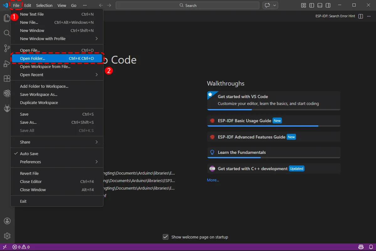
After installing the ESP-IDF development environment, select the folder to open the example.
-
In the pop-up window, select the example under the ESP32-S3-Touch-LCD-7-Demo\ESP-IDF directory, and click to select the file (here, the
01_I2C_Testfolder is used as an example).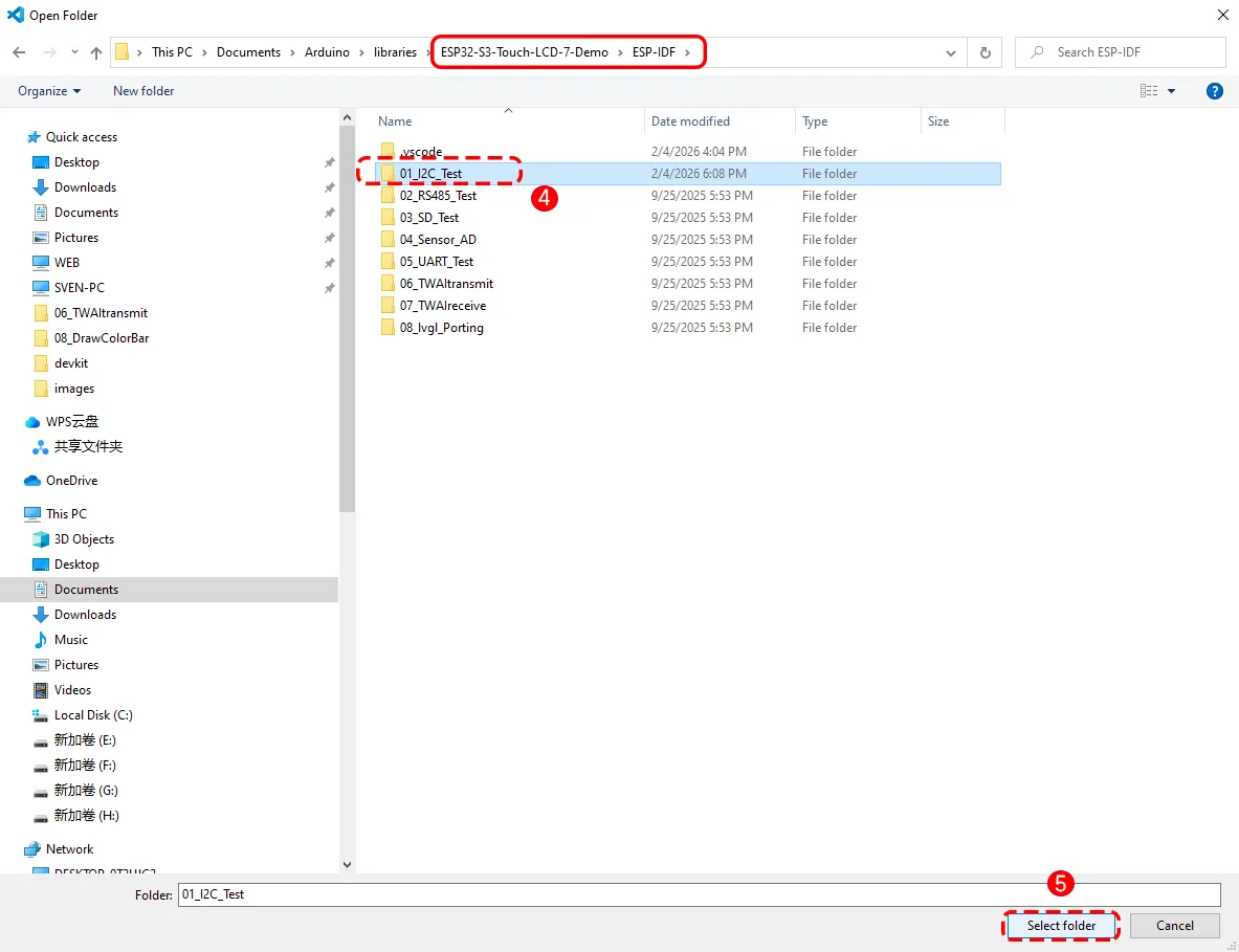
-
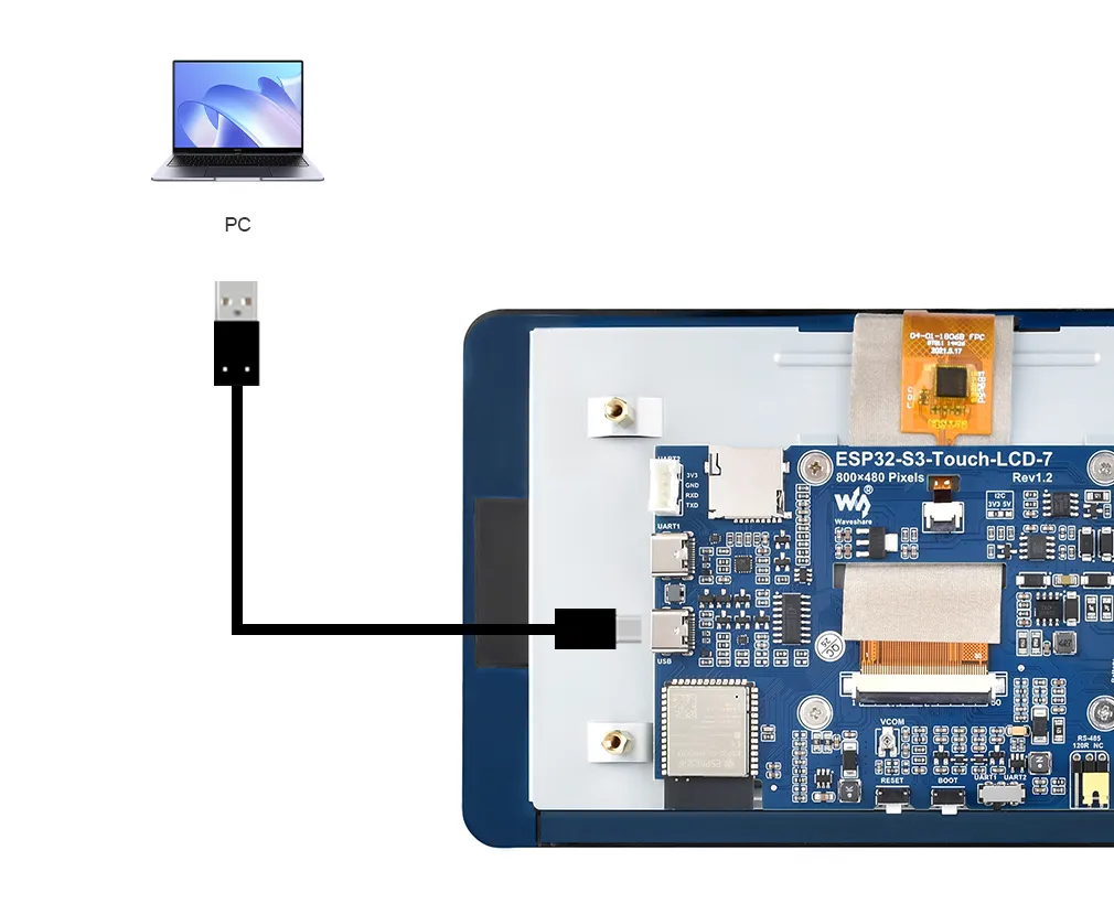
To upload the corresponding code to the ESP32-S3, connect the USB port of the ESP32-S3-Touch-LCD-7 to a USB port on your computer using a Type-C to Type-A cable.
-
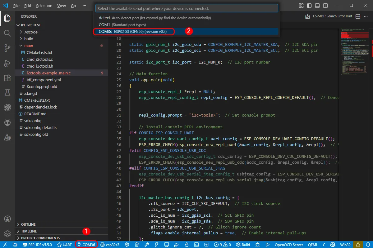
If this is the first time flashing a new project, you need to select the detected COM port. For example, here it is detected as COM36.
-
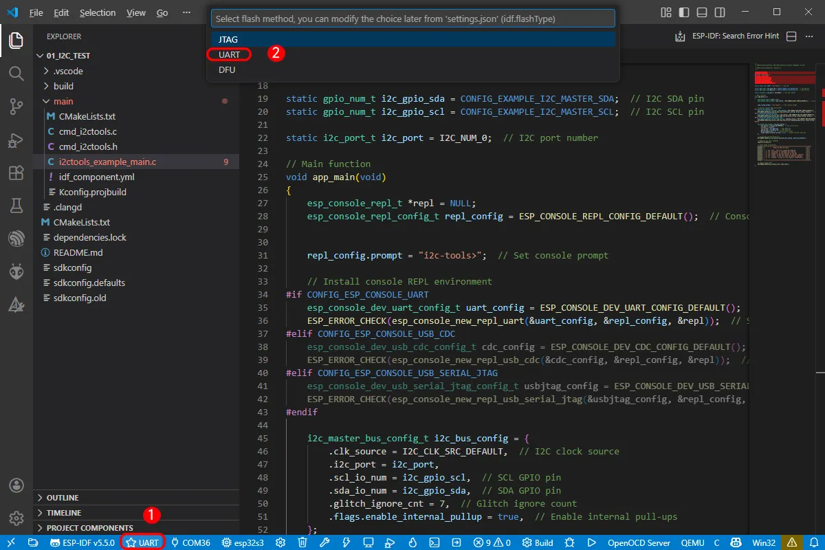
Select the download method: UART.
-
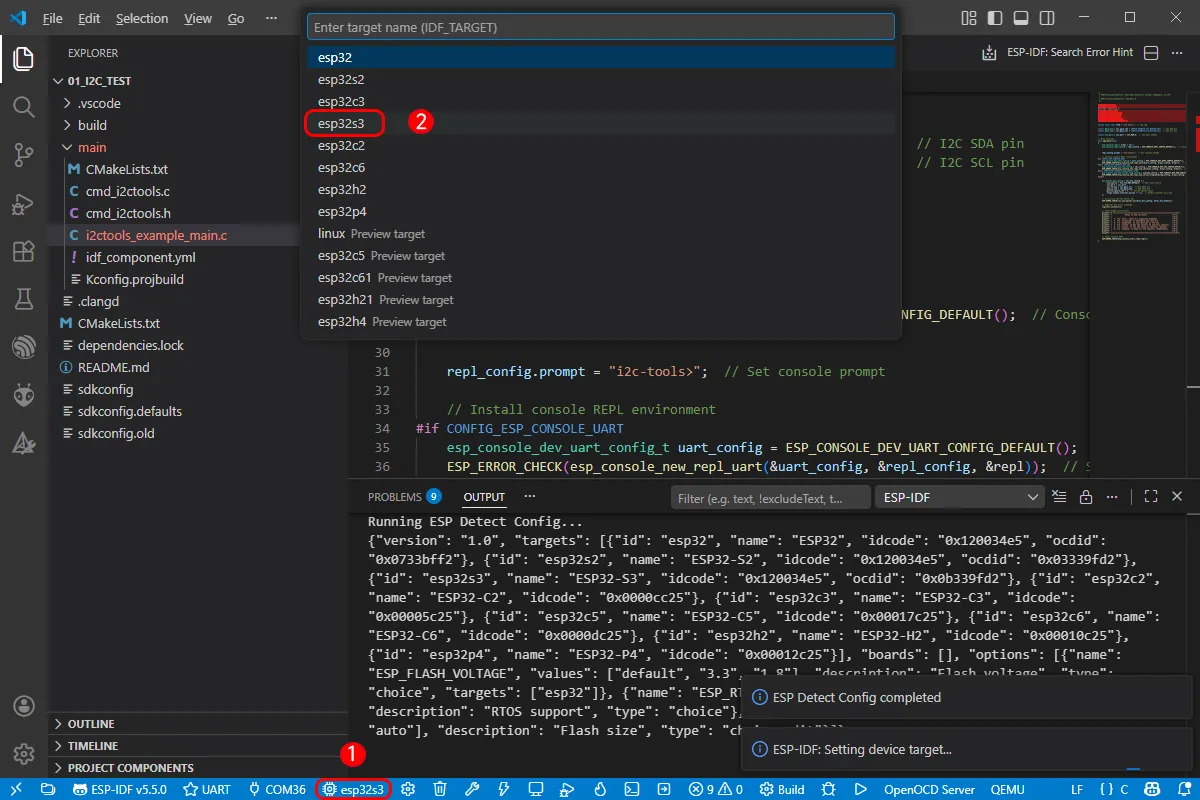
Next, select the main chip as ESP32S3.
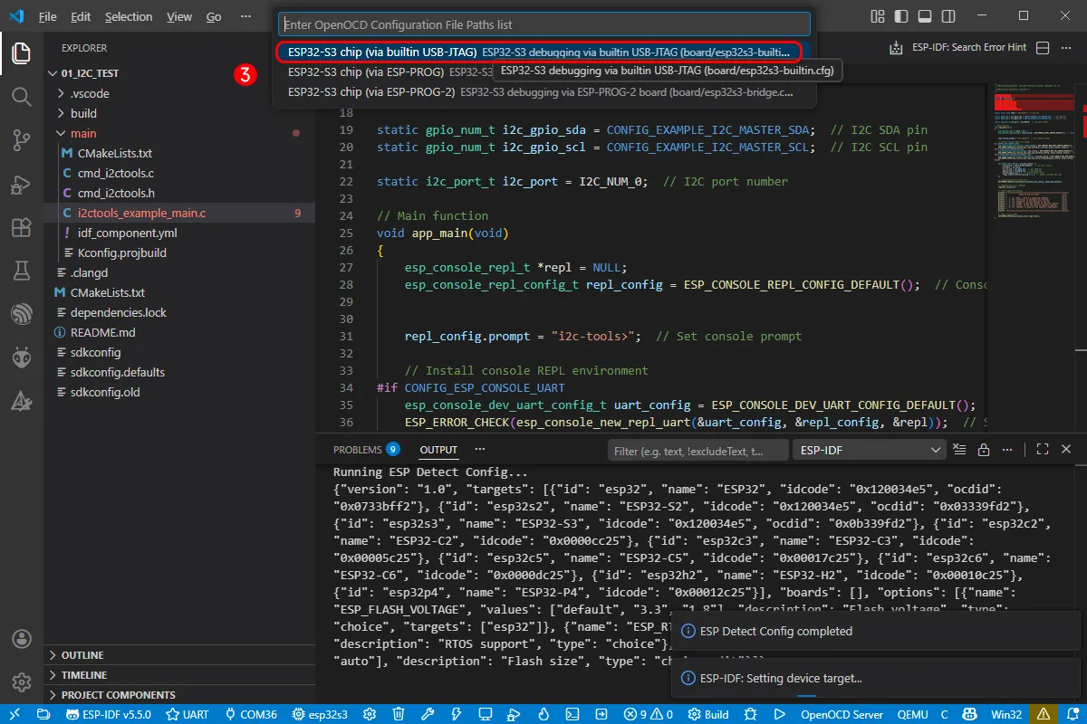
Select the path for openocd. This does not affect our process, so we can choose any option. Here, select the first one.
-
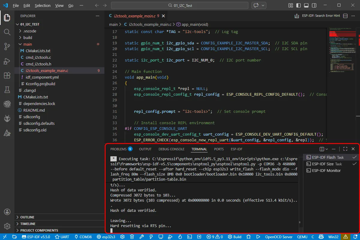
Click the following "little flame" (Build Flash Monitor) one-click button to execute Build --> Flash --> Monitor sequentially.
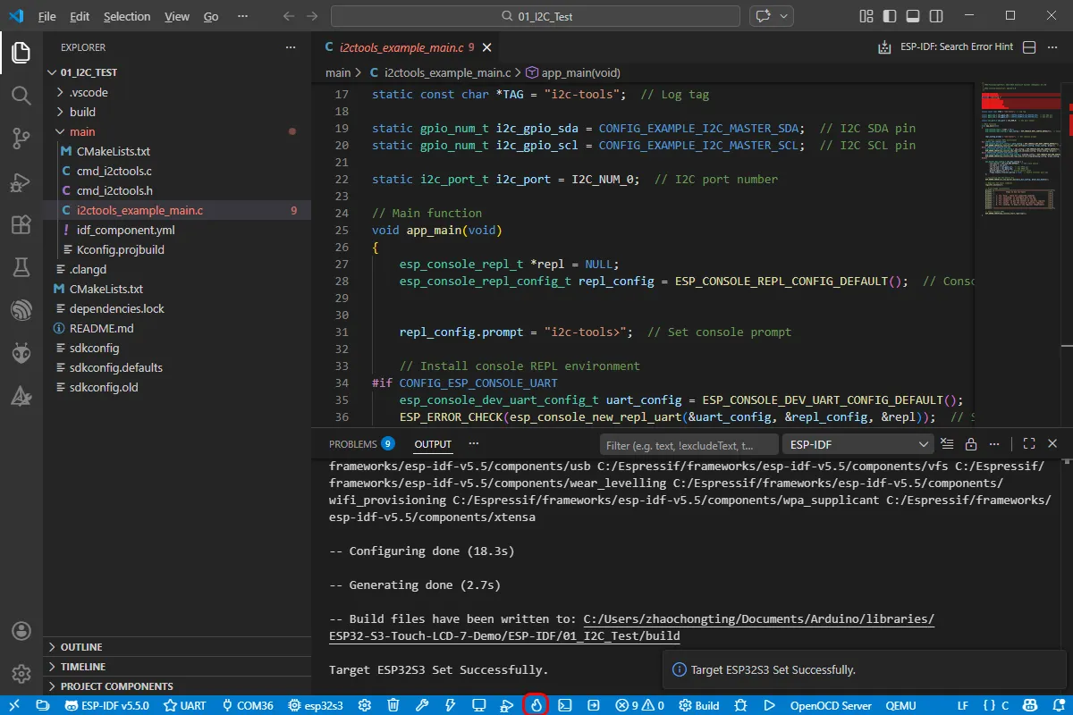
-
The board has a built-in automatic download circuit, so no manual operation is required for automatic downloading. Then wait for the compilation and flashing to complete. The first compilation may take a while.
Example
-
ESP32-S3-Touch-LCD-7 examples
Example Basic Description 01_I2C_Test Test I2C header 02_RS485_Test Test RS485 header 03_SD_Test Test TF card slot 04_Sensor_AD Test ADC header 05_UART_Test Test UART 06_TWAItransmit Test CAN header 07_TWAIreceive Test CAN header 08_lvgl_Porting Test LVGL porting -
Dependency libraries are automatically downloaded at compile time via idf component.yml.
infoFor more learning resources: IDF Component Manager
01_I2C_Test
Hardware Connection
Connect the board to the computer using a USB cable
Code Analysis
app_main():
- First, defines constants and variables related to I2C, such as log tags, I2C SDA and SCL pins, and port numbers.
- Next, installs the console REPL environment based on different configuration options for user interaction. Then configures the I2C bus, including clock source, port, pins, enabling internal pull-up resistors, etc., and initializes the I2C master bus.
- After that, registers a series of I2C tool commands, such as device detection, register read/write operations. Also prints usage instructions on how to use these commands.
- Finally, starts the console REPL, allowing users to interact with the application via the command line to perform various I2C operations, providing a convenient way to operate the I2C bus via the command line.
Operation Result
-
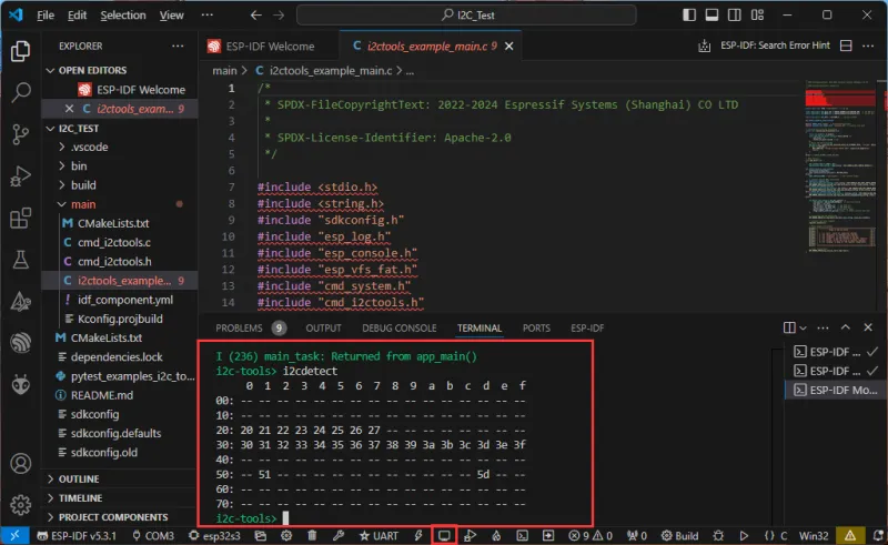
After successful flashing, open the serial terminal, enter a command, and press Enter to run it:
-
The steps are as follows:
- Use
helpto check all supported commands - Use
i2cconfigto configure your I2C bus - Use
i2cdetectto scan for devices on the bus - Use
i2cgetto read the contents of a specific register - Use
i2csetto set the value of a specific register - Use
i2cdumpto dump all registers (experimental)
- Use
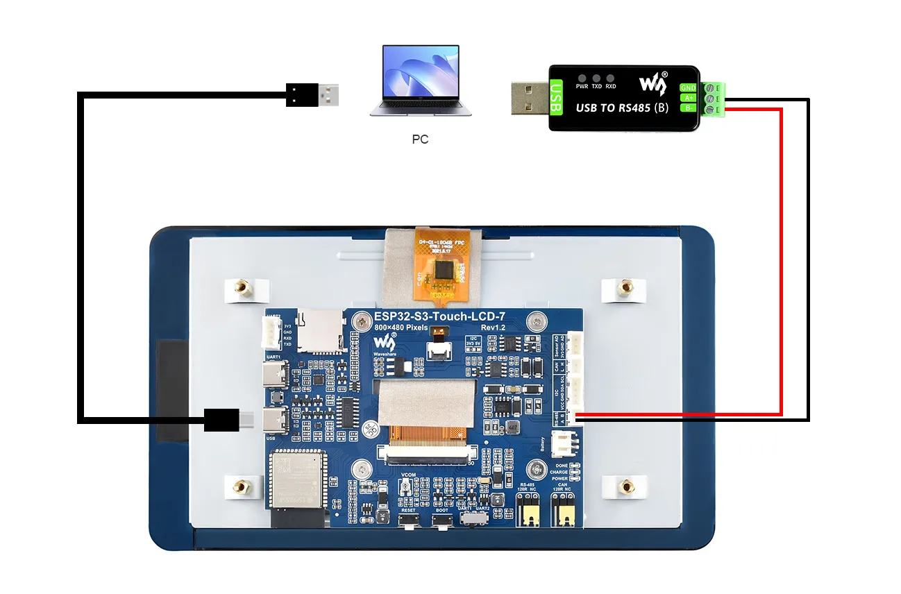
02_RS485_Test
Hardware Connection
Connect the board to the computer using a USB cable, and connect the development board to a USB to RS485 converter, as shown in the figure:
Code Analysis
echo_task():
- First, configures UART parameters including baud rate, data bits, parity, stop bits, and hardware flow control.
- Then, installs the UART driver, sets UART pins, and allocates a temporary buffer for receiving data.
- In an infinite loop, reads data from UART, writes the read data back to UART, and logs information when data is received.
Operation Result
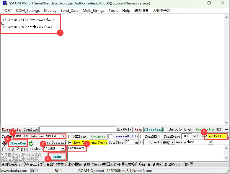
Open a serial debug assistant and send a message to the ESP32-S3-Touch-LCD-7. The device will return the received message to the serial debug assistant:
03_SD_Test
Hardware Connection
Connect the board to the computer using a USB cable
Code Analysis
waveshare_sd_card_init():
This function is mainly used to initialize the TF card. First, it initializes I2C, then pulls the TF card's CS pin low via the I2C control chip. Next, configure the TF card mounting options, including whether to format when mounting fails, the maximum number of files, and the allocation unit size, etc. After that, initialize the SPI bus and mount the TF card file system using the configured SPI bus and mount options. If mounting is successful, return ESP_OK, indicating that the TYF card initialization is complete.
waveshare_sd_card_test():
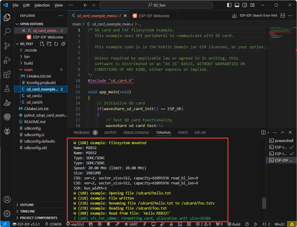
This function is used to test the functionality of the TF card. First, it prints information about the initialized TF card. Then create a file, write data into it, rename the file, and read the content of the renamed file. Next, format the file system and check if the file has been deleted after formatting. Finally, create a new file and read its content, unmount the TF card and free up SPI bus resources when the test is complete.
Operation Result
After successful flashing, the serial port prints information about the storage card, such as name, type, capacity, and maximum supported frequency, then creates a file, writes data, renames the file, and reads the renamed file:
04_Sensor_AD_Test
Hardware Connection
- Connect the board to the computer using a USB cable
- Connect the PH2.0 to 2.54mm male connector to the Sensor AD interface of the board
Code Analysis
app_main():
- First, it defines variables for storing the current ADC value and declares a calibration function.
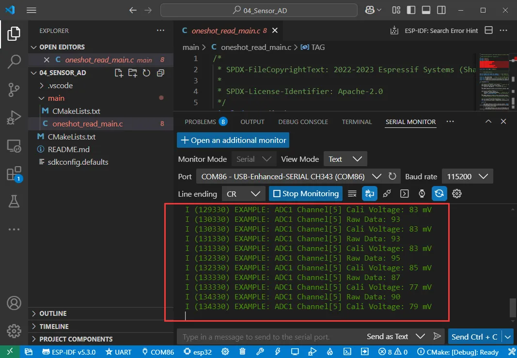
- Next, it initializes the ADC, sets the ADC resolution and attenuation, and then creates the ADC. In an infinite loop, it reads the current ADC value and prints it, with a 1-second delay in the loop.
Operation Result
The ESP32-S3-Touch-LCD-7 will set the ADC resolution, read the current AD value, and print it to the serial terminal:
05_UART_Test
Hardware Connection
Connect the UART port of the board to the computer using a USB cable
Code Analysis
echo_task():
- First, configures UART parameters including baud rate, data bits, parity, stop bits, and hardware flow control.
- Then, installs the UART driver, sets UART pins, and allocates a temporary buffer for receiving data.
- In an infinite loop, it reads data from UART, writes the read data back to UART, and logs information when data is received.
Operation Result
Open a serial debug assistant and send a message to the ESP32-S3-Touch-LCD-7. The device will return the received message to the serial debug assistant:

06_TWAItransmit
Hardware Connection
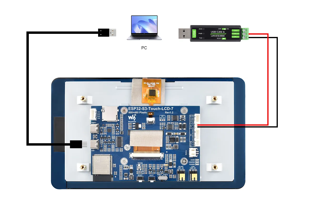
Connect the board to the computer using a USB cable, and connect the development board to a USB to CAN Adapter, as shown in the figure:
Code Analysis
waveshare_twai_transmit():
- If the driver is not installed, wait for a period and then return a failure status.
- Read triggered alerts and obtain TWAI status information.
- Print corresponding log information based on different alert types, including error passive alerts, bus error alerts, transmission failure alerts, and transmission success alerts, and print related status information.
- Determine if it is time to send a message; if so, send the message and update the last send time.
Operation Result
-
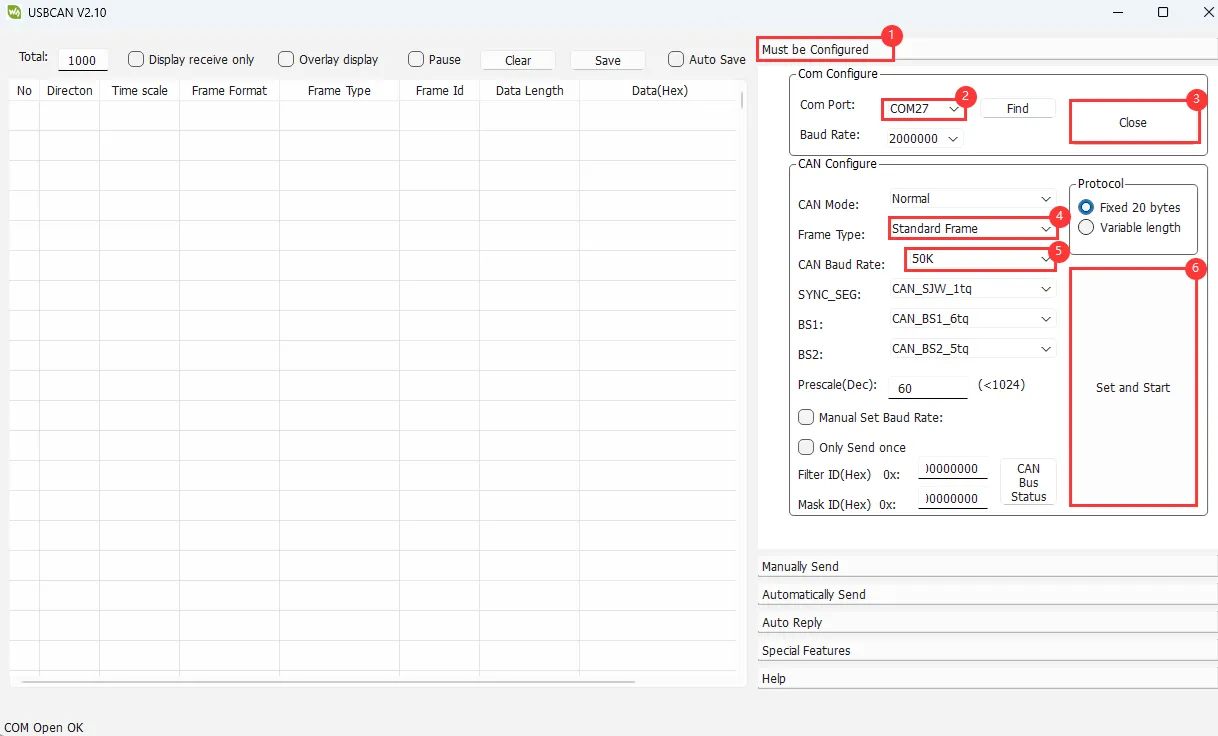
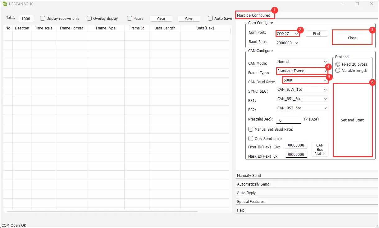
The serial port prints successful CAN message sends. After configuring USB-CAN-A_TOOL and starting it, you can see the CAN messages sent by the ESP32-S3-Touch-LCD-7.
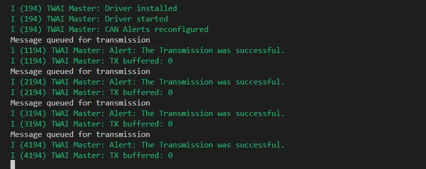
-
Then observe USB-CAN-A_TOOL to see the CAN messages sent by the ESP32-S3-Touch-LCD-7.
07_TWAIreceive
Hardware Connection
Connect the board to the computer using a USB cable, and connect the development board to a USB to CAN Adapter, as shown in the figure:
Code Analysis
waveshare_twai_receive():
- If the driver is not installed, wait for a period and then return a failure status.
- Read triggered alerts and obtain TWAI status information.
- Print corresponding log information based on different triggered alert types, including error passive alerts, bus error alerts, and receive queue full alerts, and print related status information.
- If a receive data alert is triggered, it loops to receive messages and calls the handle_rx_message function to process each received message. Finally, it returns a success status.
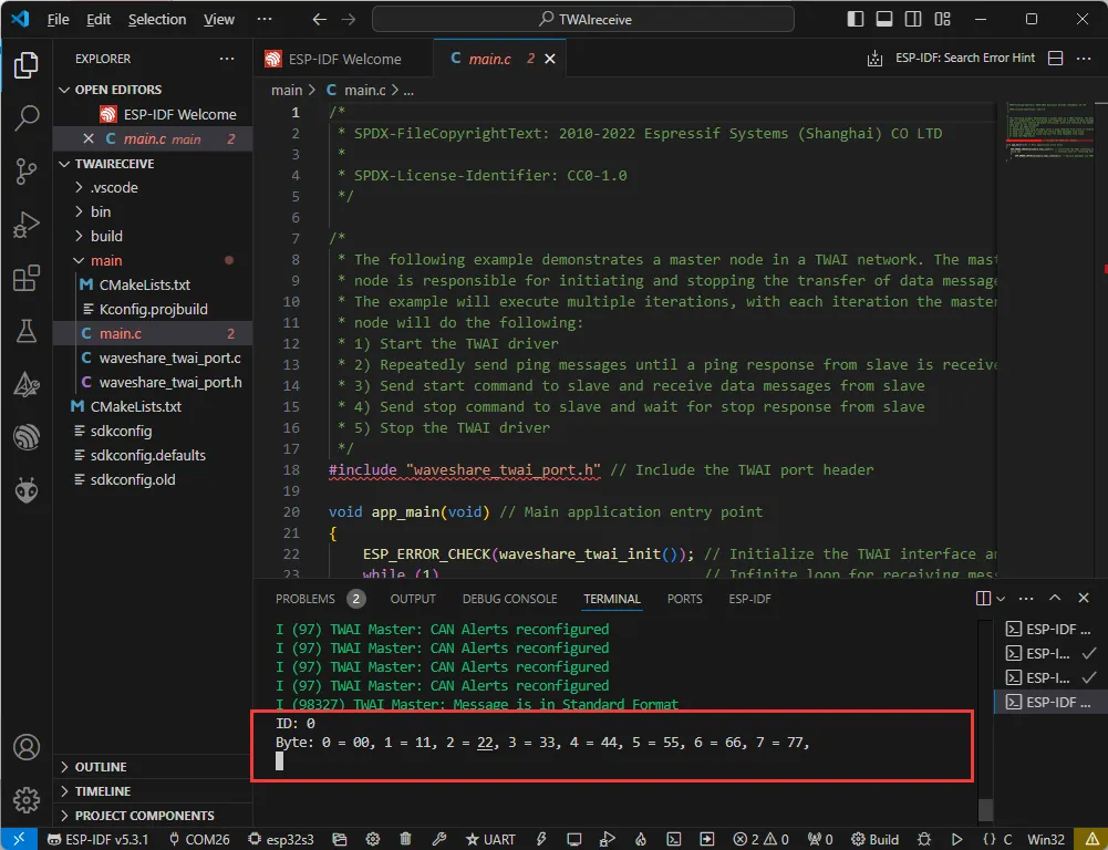
Operation Result
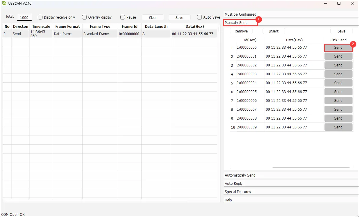
-
The ESP32-S3-Touch-LCD-7 waits for messages sent by the USB-CAN-A_TOOL. If received successfully, it prints them to the serial port.
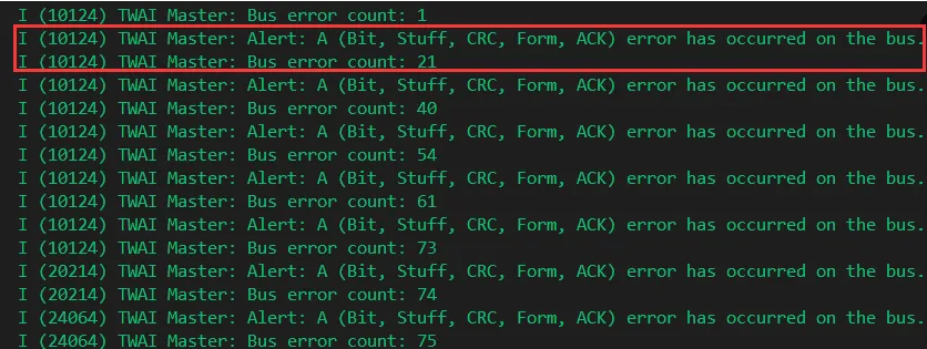
-
If the following error occurs, click the serial monitor and resend the data using the debug tool. (If the Reset button is pressed, you may sometimes need to click the serial monitor again):
08_lvgl_Porting
Hardware Connection
Connect the board to the computer using a USB cable
Code Analysis
app_main():
- Initializes the Waveshare ESP32-S3 RGB LCD, then optionally turns the screen backlight on or off.
- Next, it prints a message indicating that LVGL example content will be displayed. Since LVGL APIs are not thread-safe, it first locks a mutex.
- Then, it optionally runs different LVGL example programs, such as
lv_demo_stress,lv_demo_benchmark,lv_demo_music,lv_demo_widgets, orexample_lvgl_demo_ui, etc. - Finally, it releases the mutex.
Code Modification
In waveshare_rgb_lcd_port.h, there is a macro definition to choose whether to enable touch functionality. A value of 0 corresponds to touch disabled, a value of 1 corresponds to touch enabled. Choose based on the purchased model.
#define CONFIG_EXAMPLE_LCD_TOUCH_CONTROLLER_GT911 0 // 1 initiates the touch, 0 closes the touch.
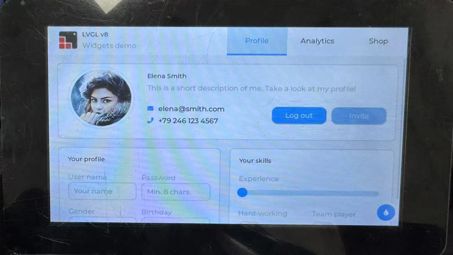
Operation Result
After successful flashing, press the Reset button to run the example.