User Guide
To help users quickly understand the various functions of the product, we provide a series of test examples to familiarize customers with the use of each interface. In addition to the ESP32-S3-Touch-LCD-7 main unit and its included cables, the following components are required to run the examples:
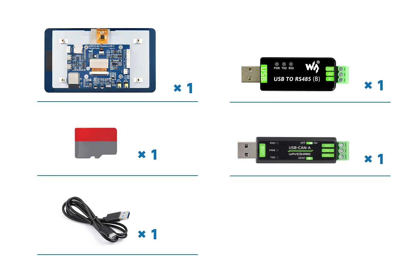
Component Preparation
- ESP32-S3-Touch-LCD-7 ×1
- TF card ×1 (not required, needed only for TF card examples)
- USB cable Type-A male → Type-C male ×1
- USB to RS485 Bidirectional Converter ×1 (not required, needed only for RS485 interface examples)
- USB to CAN Adapter / Analyzer ×1 (not required, needed only for CAN interface examples)
Precautions
-
The development board features an automatic download circuit. The Type-C interface labeled UART is used for program download and log printing. After downloading, press the RESET button to run the program.
-
Pay attention to the PCB antenna area during use, avoiding metal or plastic parts from touching the antenna location.
-
The TF card supports SPI / MMC communication. Note that the SD_CS pin must be driven by EXIO4 of the CH422G.
-
The development board brings out ADC, CAN, I2C, and RS485 peripheral pins via PH2.0 connectors. Use PH2.0 → 2.54 mm Dupont male adapter cables to connect external sensors.
-
The CAN and RS485 peripherals are connected to 120 Ω termination resistors via jumpers by default. You can select NC to disconnect the termination resistors.
-
The 7-inch screen occupies most GPIOs. The development board uses the CH422G IO expander chip for control such as reset and backlight.
-
The PH2.0 lithium battery connector supports only a single-cell 3.7 V lithium battery.
Do not connect multiple battery packs simultaneously for charging or discharging. A single-cell capacity of ≤ 2000 mAh is recommended. -
The board's CH422G and touch controller occupy the following I²C slave addresses.
Do not use I²C devices with the same addresses:0 1 2 3 4 5 6 7 8 9 a b c d e f00: - - - - - - - - - - - - - - - -10: - - - - - - - - - - - - - - - -20: 20 21 22 23 24 25 26 27 - - - - - - - -30: 30 31 32 33 34 35 36 37 38 39 3a 3b 3c 3d 3e 3f40: - - - - - - - - - - - - - - - -50: - - - - - - - - - - - - - - 5d -60: - - - - - - - - - - - - - - - -70: -
⚠️ USB Download Precautions (Important)
If the port is not recognized, please enter Boot mode:
- Press and hold the BOOT button
- Connect the USB cable to the computer
- Release the BOOT button
After the download is complete, press the RESET button to run the program.
Performance Notes (ESP-IDF & LVGL)
Currently, under the ESP-IDF v5.3 environment, using single-core to run the LVGL benchmark example:
- Average frame rate limit: 26 FPS
- Interface frame rate: 41 FPS
- PCLK: 21 MHz
The following options must be configured in menuconfig before compilation:
In ESP-IDF, menuconfig is the project configuration interface used to edit options stored in sdkconfig before building. Open an ESP-IDF terminal in the example project directory and run idf.py menuconfig; if you use the ESP-IDF extension for VS Code, open the SDK Configuration editor to edit the same settings. For more details, refer to Espressif's Project Configuration Guide.
CONFIG_FREERTOS_HZ=1000
CONFIG_ESP_DEFAULT_CPU_FREQ_MHZ_240=y
CONFIG_ESPTOOLPY_FLASHMODE_QIO=y
CONFIG_ESPTOOLPY_FLASHFREQ_120M=y     # Must be consistent with PSRAM
CONFIG_SPIRAM_MODE_OCT=y
CONFIG_IDF_EXPERIMENTAL_FEATURES=y
CONFIG_SPIRAM_SPEED_120M=y            # Must be consistent with FLASH
CONFIG_SPIRAM_FETCH_INSTRUCTIONS=y
CONFIG_SPIRAM_RODATA=y
CONFIG_ESP32S3_DATA_CACHE_LINE_64B=y
CONFIG_COMPILER_OPTIMIZATION_PERF=y
For detailed LCD and LVGL performance descriptions, please refer to Performance Documentation