ESP32-S3-Touch-LCD-7B
![]()
| SKU | Product |
|---|---|
| 31726 | ESP32-S3-Touch-LCD-7B |
| 31727 | ESP32-S3-LCD-7B |
Product Introduction
Product Overview
This is a low-cost, high-performance MCU development board designed by Waveshare. It supports 2.4GHz Wi-Fi and BLE 5, integrates large-capacity Flash and PSRAM, and features an onboard 7inch capacitive touch LCD screen, enabling smooth operation of GUI programs like LVGL. Combined with various peripheral interfaces (such as CAN, I2C, and RS485), it facilitates rapid development of HMI and other applications for the ESP32-S3. With a wide range of functions and interfaces, it can meet power consumption requirements in Internet of Things (IoT), mobile devices, smart home and other applications.
Features
- Powered by a high-performance Xtensa 32-bit LX7 dual-core processor, with a main frequency of up to 240MHz
- Supports 2.4 GHz Wi‑Fi (802.11 b/g/n) and Bluetooth 5 (LE) with an onboard antenna
- Built-in 512KB SRAM and 384KB ROM, stacked with 16MB Flash and 8MB PSRAM
- Onboard 7inch LCD screen with 1024 × 600 resolution, 65K colors
- Supports I2C interface for capacitive touch control (optional), 5-point touch, with interrupt support
- Onboard CAN, RS485, I2C interfaces, TF card slot, and integrated full-speed USB
- Onboard LED indicators for indicating the power and battery charging status
- Supports adjusting the backlight brightness and reading the current battery voltage
- Supports precise control features like flexible clocking and independent module power supply settings, enabling low-power modes for multiple scenarios
Onboard Resources
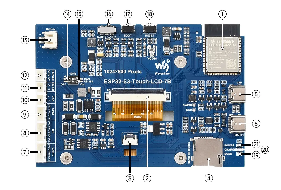
- ESP32-S3-WROOM-1-N16R8 Module
WiFi/Bluetooth SoC module, 240MHz operating frequency, stacked with 8MB PSRAM and 16MB Flash - Display Panel Connector
- Touch Panel Connector
- TF Card Slot
- USB Type-C Port
- USB TO UART Type-C Port
- UART Header: 6 and 7 share the same UART, selectable via the UART selection switch; recommended cable: HY2.0 4P to Dupont male 4P
- I2C Header: Recommended to use the included HY2.0 4P to Dupont male 4P cable
- Sensor Header: Recommended to use the included HY2.0 3P to Dupont male 3P cable
- CAN Header: Recommended to use the included HY2.0 2P to Dupont male 2P cable
- RS485 Header: Recommended to use the included HY2.0 2P to Dupont male 2P cable
- 5 V output: Recommended to use the included HY2.0 2P to Dupont male 2P cable
- 3.7V Single-cell Lithium Battery PH2.0 Header
- CAN Terminal Resistor Selection Interface
- RS485 Terminal Resistor Selection Interface
- UART Selection Switch
Selects between UART1 and UART2 - BOOT Button
Press and hold while powering on for program flashing - RESET Button
Press to reset the controller - DONE
Lithium battery charge complete indicator - CHARGE
Lithium battery charging indicator - POWER
Power indicator
Interface Description
When using the ESP32-S3-Touch-LCD-7B, it's important to understand the hardware connections for different peripherals.
LCD Interface: Connector for the LCD cable (click to expand)
| ESP32-S3 | LCD | Description |
|---|---|---|
| GPIO0 | G3 | Green data bit 3 |
| GPIO1 | R3 | Red data bit 3 |
| GPIO2 | R4 | Red data bit 4 |
| GPIO3 | VSYNC | Vertical sync signal |
| GPIO5 | DE | Data enable signal |
| GPIO7 | PCLK | Pixel clock signal |
| GPIO10 | B7 | Blue data bit 7 |
| GPIO14 | B3 | Blue data bit 3 |
| GPIO17 | B6 | Blue data bit 6 |
| GPIO18 | B5 | Blue data bit 5 |
| GPIO21 | G7 | Green data bit 7 |
| GPIO38 | B4 | Blue data bit 4 |
| GPIO39 | G2 | Green data bit 2 |
| GPIO40 | R7 | Red data bit 7 |
| GPIO41 | R6 | Red data bit 6 |
| GPIO42 | R5 | Red data bit 5 |
| GPIO45 | G4 | Green data bit 4 |
| GPIO46 | HSYNC | Horizontal sync signal |
| GPIO47 | G6 | Green data bit 6 |
| GPIO48 | G5 | Green data bit 5 |
| IO EXTENSION | LCD | - |
| EXIO2 | DISP | Backlight enable pin |
| EXIO6 | LCD_VDD_EN | VCOM voltage enable pin |
Touch Interface: Connects to the touch cable (click to expand)
| ESP32-S3 | Touch | Description |
|---|---|---|
| GPIO4 | TP_IRQ | Touch interrupt pin |
| GPIO8 | TP_SDA | Touch data pin (I2C) |
| GPIO9 | TP_SCL | Touch clock pin (I2C) |
| IO EXTENSION | Touch | - |
| EXIO1 | TP_RST | Touch reset pin |
USB Interface: Used for power supply and flashing (click to expand)
| ESP32-S3 | USB | Description |
|---|---|---|
| GPIO19 | USB_DN | Data line D- |
| GPIO20 | USB_DP | Data line D+ |
| IO EXTENSION | USB | - |
| EXIO5 | USB_SEL | Pull low to set USB mode, otherwise CAN mode |
TF Card Interface: Connects to the TF card (click to expand)
| ESP32-S3 | TF | Description |
|---|---|---|
| GPIO11 | MOSI | TF card input pin |
| GPIO12 | SCK | TF card clock pin |
| GPIO13 | MISO | TF card output pin |
| IO EXTENSION | TF | - |
| EXIO4 | SD_CS | TF card chip select pin, active low |
RS485 Interface: Onboard RS485 interface for direct device communication; transmission/reception mode is switched automatically (click to expand)
| ESP32-S3 | RS485 | Description |
|---|---|---|
| GPIO16 | RS485_RXD | Data input |
| GPIO15 | RS485_TXD | Data output |
CAN Interface: Enables transmission/reception control, data analysis, acquisition, and monitoring for CAN bus networks (click to expand)
| ESP32-S3 | CAN | Description |
|---|---|---|
| GPIO20 | CANTX | Data output |
| GPIO19 | CANRX | Data input |
| IO EXTENSION | CAN | - |
| EXIO5 | CAN_SEL | Pull high to set CAN mode, otherwise USB mode |
I2C Interface: Connects to the I/O expander chip, touch interface, and external interfaces (click to expand)
ESP32-S3 provides multiple hardware I2C channels. Currently, pins GPIO8 (SDA) and GPIO9 (SCL) are used for the I2C bus.
Peripherals such as the I/O expander chip and touch screen are connected via this I2C interface.
| ESP32-S3 | I2C | Description |
|---|---|---|
| GPIO8 | SDA | I2C data pin |
| GPIO9 | SCL | I2C clock pin |
- PH2.0 Battery Interface: The development board uses the CS8501 high-efficiency charge/discharge management IC to boost the voltage from a single-cell lithium battery to 5V. The default charging current is 580mA. Users can change resistor R45 to modify the charging current. For details, please refer to the ESP32-S3-Touch-LCD-7B Schematic
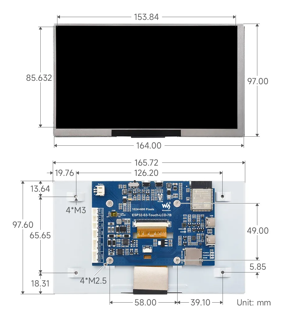
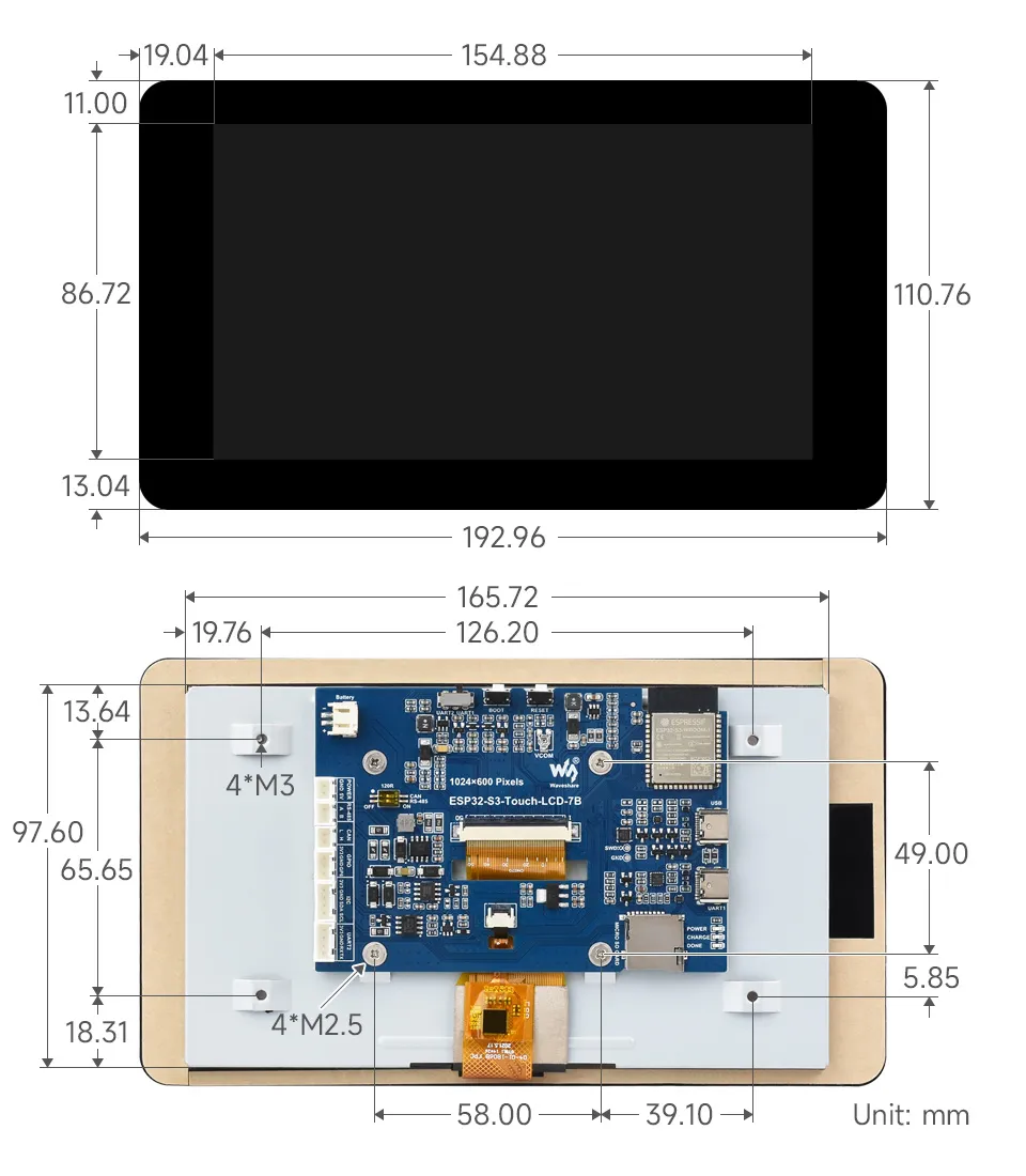
Dimensions
Without Touch Version
With Touch Version
Specifications
Basic Parameters
| Item | Specification |
|---|---|
| Processor | High-performance Xtensa 32-bit LX7 dual-core processor, up to 240 MHz |
| Wi-Fi/Bluetooth | Supports 2.4 GHz Wi-Fi (802.11 b/g/n) and Bluetooth 5 (LE), onboard antenna |
| Flash | 16MB Flash |
| PSRAM | 8MB PSRAM |
| Power Supply | Type-C 5V |
Screen Parameters
| Item | Specification |
|---|---|
| Resolution | 1024 × 600 |
| Display Color | 65K colors |
| Display Interface | RGB |
| Display Panel | IPS |
| Viewing Angle | 170° |
| Screen Brightness | 235 cd/m² |
| Touch Type | Capacitive |
| Touch Panel | Tempered Glass |
Peripheral Interfaces and Others
| Item | Specification |
|---|---|
| Communication Interfaces | CAN, RS485, I2C, USB |
| Power Consumption | 5V 350mA |
| Operating Temperature | 0℃ ~ 65℃ |
| Product Dimensions (L×W) | Without Touch Version: 164×97 (mm); With Touch Version: 192.96×110.76 (mm) |