Working with ESP-IDF
This chapter includes the following sections:
- ESP-IDF Getting Started
- Setting Up Development Environment (Windows)
- Common Example Descriptions (Brief Overview and Code Explanation)
ESP-IDF Getting Started
New to ESP32 ESP-IDF development and looking to get started quickly? We have prepared a general Getting Started Tutorial for you.
- Section 1: Environment Setup
- Section 2: Running Examples
- Section 3: Creating a Project
- Section 4: Using Components
- Section 5: Debugging
- Section 6: FreeRTOS
- Section 7: Peripherals
- Section 8: Wi-Fi Programming
- Section 9: BLE Programming
Please Note: This tutorial uses the ESP32-S3-Zero as a teaching example, and all hardware code is based on its pinout. Before you start, it is recommended that you check the pinout of your development board to ensure the pin configuration is correct.
Setting Up Development Environment
The following guide uses Windows as an example, demonstrating development using VS Code + the ESP-IDF extension. macOS and Linux users should refer to the official documentation.
The screenshots in this section use ESP-IDF V5.5.2 as an example. When installing, please select the ESP-IDF version that matches your board's example.
Install the ESP-IDF Development Environment
-
Download the installation manager from the ESP-IDF Installation Manager page. This is Espressif's latest cross-platform installer. The following steps demonstrate how to use its offline installation feature.
Click the Offline Installer tab on the page, then select Windows as the operating system and the ESP-IDF version you need (the version shown in the screenshot is for reference only — choose the version that fits your actual needs).

After confirming your selection, click the download button. The browser will automatically download two files: the ESP-IDF Offline Package (.zst) and the ESP-IDF Installer (.exe).

Please wait for both files to finish downloading.
-
Once the download is complete, double-click to run the ESP-IDF Installer (eim-gui-windows-x64.exe).
The installer will automatically detect if the offline package exists in the same directory. Click Install from archive.

Next, select the installation path. We recommend using the default path. If you need to customize it, ensure the path does not contain Chinese characters or spaces. Click Start installation to proceed.

-
When you see the following screen, the ESP-IDF installation is successful.

-
We recommend installing the drivers as well. Click Finish installation, then select Install driver.

Install Visual Studio Code and the ESP-IDF Extension
-
Download and install Visual Studio Code.
-
During installation, it is recommended to check Add "Open with Code" action to Windows Explorer file context menu to facilitate opening project folders quickly.
-
In VS Code, click the Extensions icon
 in the Activity Bar on the side (or use the shortcut Ctrl + Shift + X) to open the Extensions view.
 -
Enter ESP-IDF in the search box, locate the ESP-IDF extension, and click Install.

-
For ESP-IDF extension versions ≥ 2.0, the extension will automatically detect and recognize the ESP-IDF environment installed in the previous steps, requiring no manual configuration.
If installation fails or a reinstall is needed, you can try deleting the C:\Users\%Username%\esp and C:\Users\%Username%\.espressif folders and then retry.
Flashing Example
-
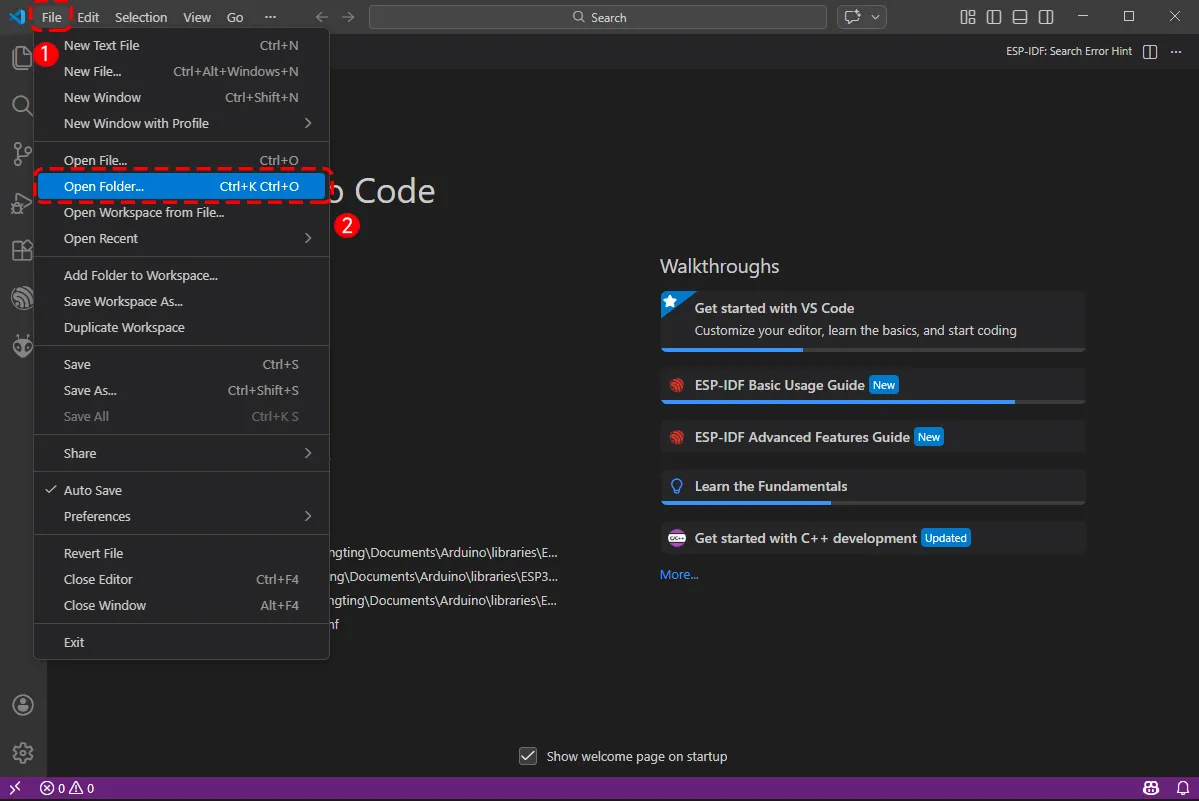
After installing the ESP-IDF development environment, select the folder to open the example.
-
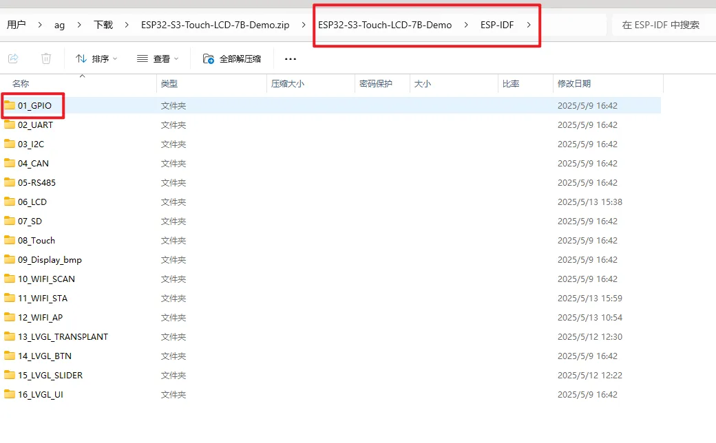
In the pop-up window, select the example under the ESP-IDF directory within the extracted example package, and click to select a file (here, the 01_GPIO folder is used as an example).
-
To upload the corresponding code to the ESP32-S3, use a Type-C to Type-A cable to connect the USB TO UART Type-C interface of the ESP32-S3-Touch-LCD-7B to a USB port on your computer.
-
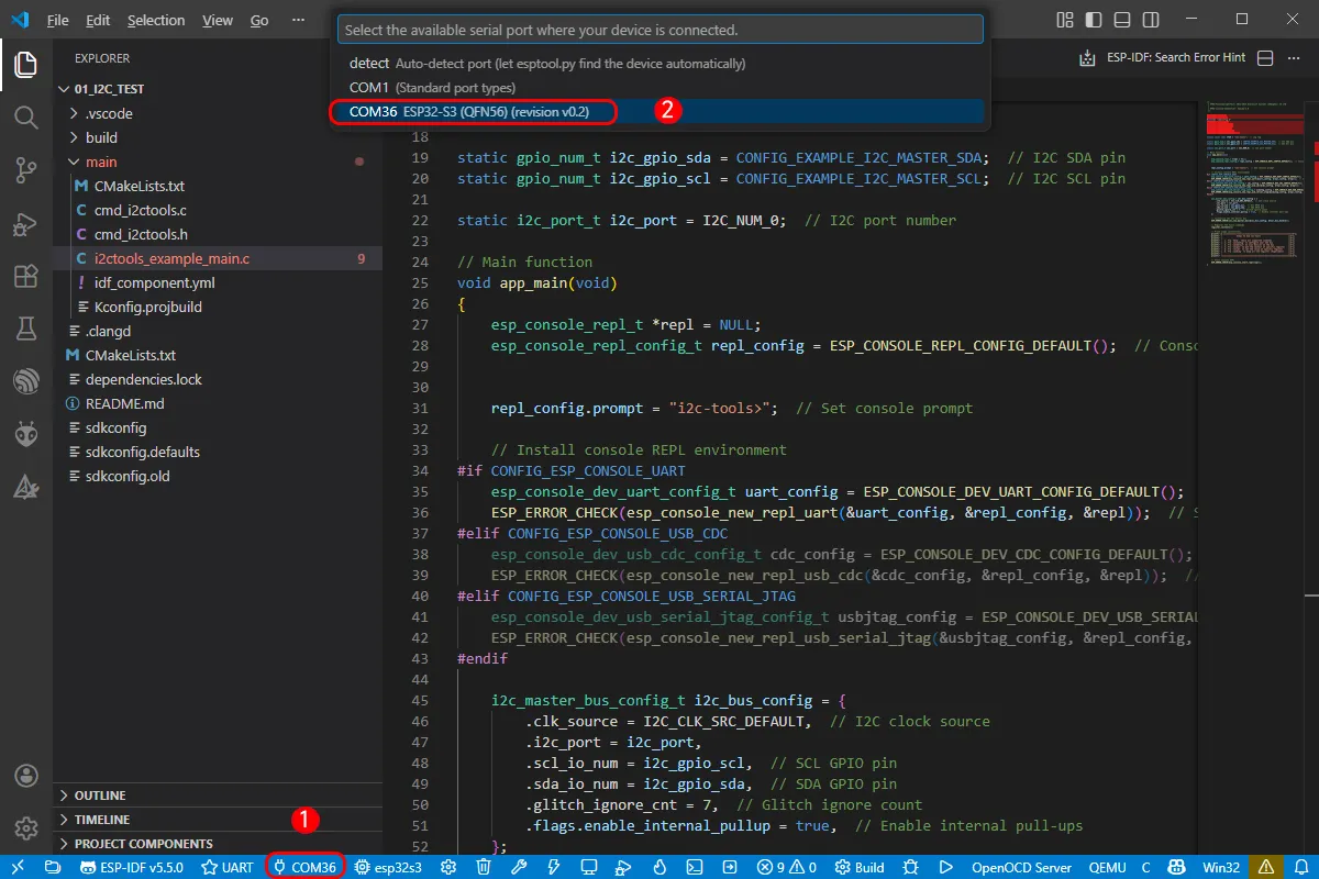
If this is the first time flashing a new project, you need to select the detected COM port. For example, here it is detected as COM36.
-
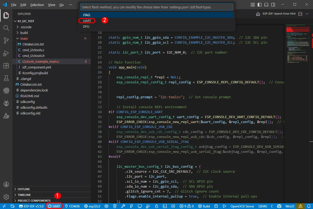
Select the download method: UART.
-
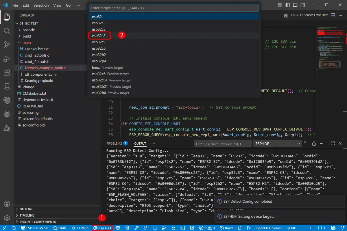
Next, select the main chip as ESP32S3.
Select the path for openocd. This does not affect our process, so we can choose any option. Here, select the first one.
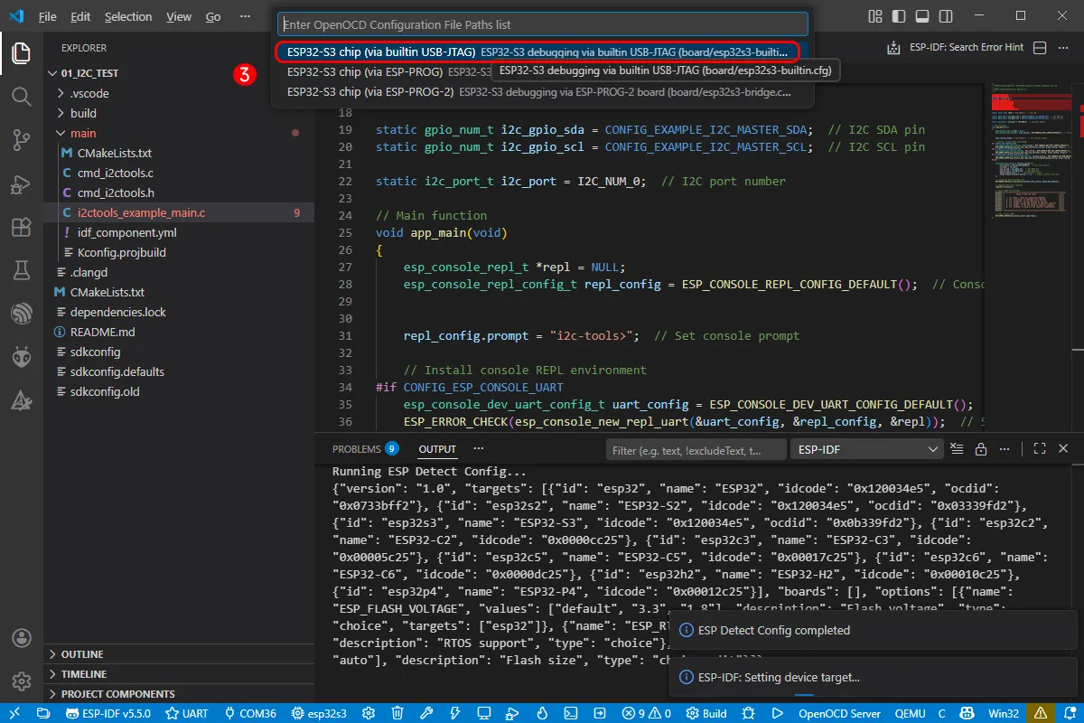
-
Click the following "little flame" (Build Flash Monitor) one-click button to execute Build --> Flash --> Monitor sequentially.
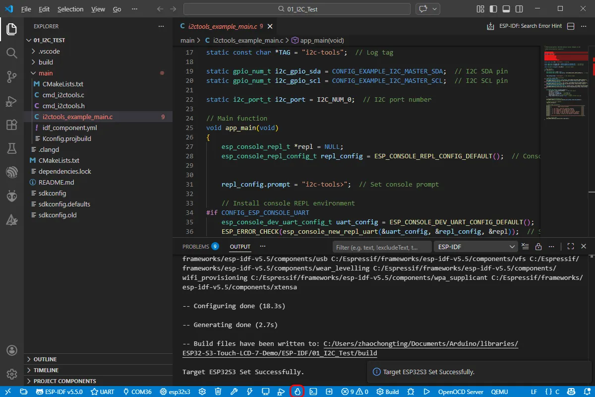
-
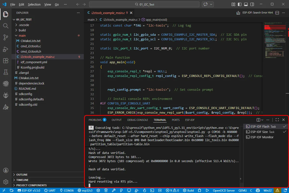
The board has a built-in automatic download circuit, so no manual operation is required for automatic downloading. Then wait for the compilation and flashing to complete. The first compilation may take a while.
Example
The demos are located in the ESP-IDF directory of the example package:
https://github.com/waveshareteam/ESP32-S3-Touch-LCD-7B/
Below are the purpose, key points, and operational effects for each example (for quick start).
| Example | Basic Description |
|---|---|
| 01_GPIO | Test GPIO output controlling an LED |
| 02_UART | Test UART serial loopback |
| 03_I2C | Test I2C communication with I/O expander for backlight control |
| 04_CAN | Test CAN interface transmission/reception and alerts |
| 05_RS485 | Test RS485 data loopback |
| 06_LCD | Test RGB LCD display and rotation |
| 07_SD | Test TF card mounting and capacity reading |
| 08_TOUCH | Test capacitive touchscreen multi-touch |
| 09_DISPLAY_BMP | Read and switch BMP images from TF card |
| 10_WIFI_SCAN | Scan for nearby WiFi networks and display the list |
| 11_WIFI_STA | Connect to a specified WiFi network as a station and display the IP address |
| 12_WIFI_AP | Create an AP hotspot and display connected devices |
| 13_LVGL_TRANSPLANT | Run the LVGL official widgets demo |
| 14_LVGL_BTN | Use an LVGL button to control an LED on/off |
| 15_LVGL_SLIDER | Use a slider to adjust brightness and display voltage |
| 16_LVGL_UI | Run a comprehensive GUI integrating various peripheral tests |
- Examples 08, 09, 13, 14, 15, 16 are only applicable to boards with a touchscreen.
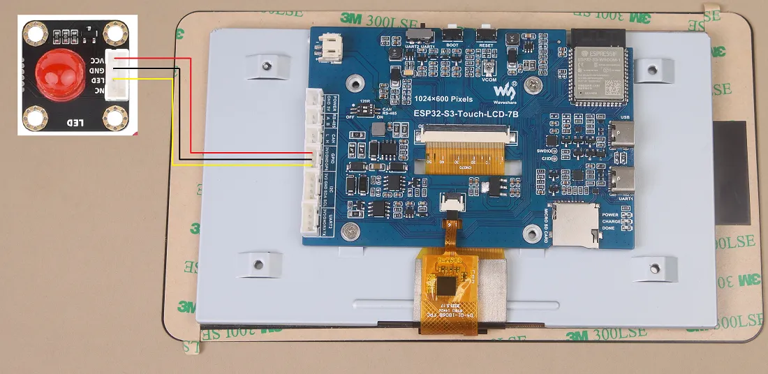
01_GPIO
Hardware Connection
- Connect the development board to a computer using a USB cable
- Connect the LED module to the specified GPIO pin (GPIO6 is used in the example)
Code Analysis
app_main():- Initializes GPIO6 and configures it as output mode
- In a loop, alternately outputs high and low levels to control the LED on/off, achieving an approximately 1 Hz blinking effect
Operation Result
-
After successful flashing, the screen has no display
-
The connected LED blinks at approximately 1 Hz

02_UART
Hardware Connection
-
Connect the UART port of the board to the computer using a USB cable

Code Analysis
app_main():- Initializes the UART peripheral, setting baud rate, data bits, parity, stop bits, etc
- Allocates a temporary buffer for receiving UART data
- In a loop, polls for UART reception. If data is received, it reads it out and immediately sends it back, implementing a simple "serial loopback" function
Operation Result
- After successful flashing, open a serial debugging assistant and send any data to the ESP32-S3-Touch-LCD-7B
- The development board echoes the received data back to the serial debugging assistant
03_I2C
Hardware Connection
- Connect the development board to a computer using a USB cable
- If an external I2C device is needed, it can be connected via the onboard I2C header
Code Analysis
app_main():- Calls
DEV_I2C_Init()to initialize the I2C bus - Calls
IO_EXTENSION_Init()to initialize the I/O expander chip - In a loop, controls the backlight pin via the I/O expander, making the screen backlight blink periodically
- Calls
DEV_I2C_Init(): Performs basic initialization of the I2C peripheralIO_EXTENSION_Init(): Initializes the I/O expander chipIO_EXTENSION_Output(uint8_t pin, uint8_t value): Controls a specified expansion pin to output high/low level
Operation Result
- After successful flashing, the screen backlight blinks at approximately 1 Hz
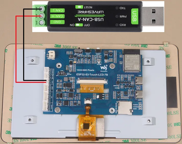
04_CAN
Hardware Connection
-
Connect the development board to a computer using a USB cable
-
Use a USB-CAN-A tool board to connect it to the board's CAN interface
Code Analysis
app_main():- Initializes I2C, I/O expansion, and the CAN interface
- Before initializing CAN, pulls
IO_EXTENSION_IO_5high to enable the CAN interface - Calls
can_init(twai_timing_config_t, twai_filter_config_t, twai_general_config_t)to complete TWAI initialization - In a loop, reads alerts using
can_read_alerts()to get the status, and logs different alert types (e.g., error passive, bus error, transmission failure, transmission success) - When a valid data frame is received, it echoes it back, implementing a CAN loopback test
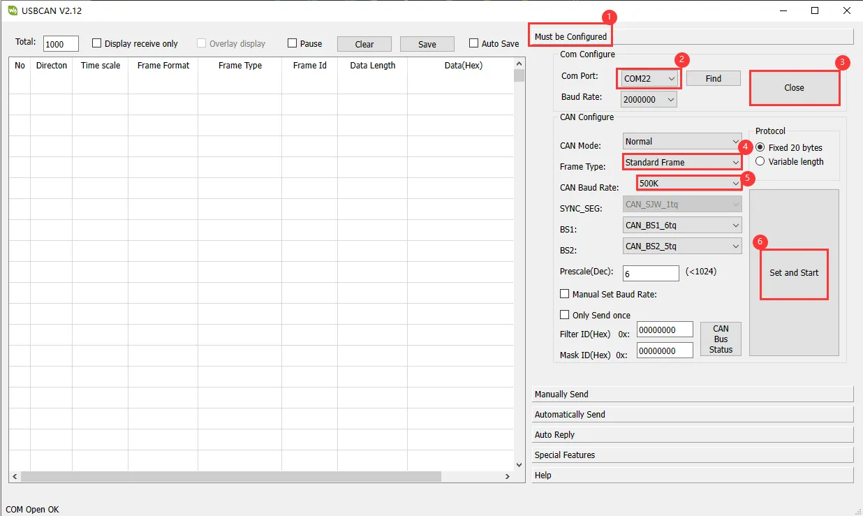
Operation Result
-
After successful flashing, the screen has no display
-
In the USB-CAN-A_TOOL, send a CAN message to the ESP32-S3-Touch-LCD-7B, and the device returns the same message

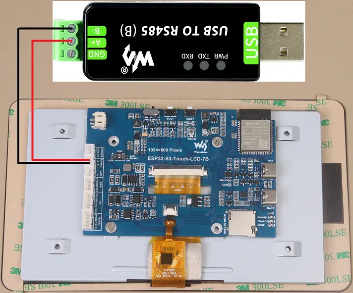
05_RS485
Hardware Connection
-
Connect the development board to a computer using a USB cable
-
Use a USB to RS485 converter to connect to the board's RS485 interface
Code Analysis
app_main():- Calls
DEV_UART_Init()to initialize the UART, setting baud rate, pins, etc - Allocates a receive buffer for caching data received via RS485
- In a loop, checks for available data. If data is received, it reads it out and immediately sends it back, implementing RS485 data loopback
- Calls
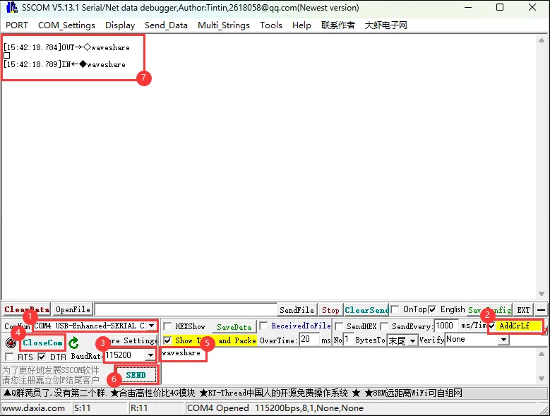
Operation Result
-
After successful flashing, open a serial debugging assistant (in RS485 mode) and send data to the ESP32-S3-Touch-LCD-7B
-
The development board echoes the received data back
06_LCD
Hardware Connection
- Connect the development board to a computer using a USB cable
Code Analysis
app_main():- Initializes I2C, I/O expansion, and the RGB LCD, then turns on the backlight
- Creates a frame buffer to store the image data to be displayed
- Initializes GUI image data, sets the image format and rotation angle (the angle can be modified in the example)
- Sequentially displays a color bar, pattern, text, and image on the screen to verify LCD functionality
waveshare_esp32_s3_rgb_lcd_init(): Completes RGB LCD initializationwaveshare_rgb_lcd_bl_on(): Turns on the LCD backlight
Operation Result
-
After successful flashing, an RGB565 color bar is displayed first
-
Then a pattern and text are displayed, followed by an image
07_SD
Hardware Connection
- Connect the development board to a computer using a USB cable
- Insert the TF card into the TF card slot on the ESP32-S3-Touch-LCD-7B
Code Analysis
app_main():- Initializes the TF card and mounts the file system
- Calls relevant functions to read the TF card's total and available space, displaying the information on the screen
sd_mmc_init(): Initializes the SD/MMC interface and mounts the file systemread_sd_capacity(uint64_t *total_capacity, uint64_t *available_capacity): Reads the total and available capacity of the TF card
Operation Result
-
After successful flashing, the screen displays information such as the TF card capacity
-
If mounting fails or no card is present, it will display "SD Card Fail!"
08_TOUCH
Hardware Connection
- Connect the development board to a computer using a USB cable
Code Analysis
app_main():- Initializes the capacitive touchscreen and display
- In a loop, reads touch points and draws them on the screen
touch_gt911_init(): Initializes the GT911 touch controllertouch_gt911_read_point(uint8_t max_touch_cnt): Reads the current touch points, identifying up to 5 points
Operation Result
-
After successful flashing, touching the screen will display touch points at the corresponding locations
-
Touching multiple points simultaneously can display up to 5 points in different colors
09_DISPLAY_BMP
Hardware Connection
- Connect the development board to a computer using a USB cable
- Copy the BMP images from the example directory to a TF card, then insert it into the development board
Code Analysis
app_main():- After initializing the TF card and LCD, reads BMP image files from the TF card
- Displays left and right arrows on the screen. Touching the arrows switches the displayed image
list_files(const char *base_path):- Traverses the specified path, reads BMP filenames, and saves them into an array
GUI_ReadBmp(UWORD Xstart, UWORD Ystart, const char *path):- Reads BMP image data from the TF card into the frame buffer.
XstartandYstartdetermine the display position
- Reads BMP image data from the TF card into the frame buffer.
Operation Result
-
After successful flashing and successful TF card mounting, the screen displays arrow icons
-
Touching the arrows allows browsing through the images on the TF card, switching left or right
10_WIFI_SCAN
Hardware Connection
- Connect the development board to a computer using a USB cable
Code Analysis
app_main():- Initializes the WiFi subsystem, configuring it in STA mode
- Calls a scan function to search for nearby 2.4 GHz WiFi networks and writes the results into a buffer
wifi_scan(): Responsible for performing the actual WiFi scan and saving the results
Operation Result
-
After successful flashing, the development board starts scanning for nearby WiFi networks
-
After the scan completes, the screen displays a list of found WiFi network names (Chinese SSIDs may not display correctly)
11_WIFI_STA
Hardware Connection
- Connect the development board to a computer using a USB cable
Code Analysis
app_main():- Initializes WiFi in STA mode
- Uses preset SSID/password to connect to a specified 2.4 GHz WiFi network
- After successful connection, displays the obtained IP address on the screen
Operation Result
-
After successful flashing, the development board connects to the configured WiFi network
-
After successful connection, the screen displays the current IP address
12_WIFI_AP
Hardware Connection
- Connect the development board to a computer using a USB cable
Code Analysis
app_main():- Configures WiFi in AP mode
- Creates a hotspot named "ESP32-S3-Touch-LCD-7B"
- Real-time statistics and display of MAC addresses of devices currently connected to the hotspot
Operation Result
-
After successful flashing, the development board operates as a hotspot
-
The screen displays a list of MAC addresses of connected devices
13_LVGL_TRANSPLANT
Hardware Connection
- Connect the development board to a computer using a USB cable
Code Analysis
app_main():- Completes LCD, touch, and LVGL-related initializations
- Runs LVGL's
lv_demo_widgetsdemonstration interface, showcasing common widgets
Operation Result
-
After successful flashing, the screen enters the
lv_demo_widgetsinterface, allowing touch interaction
Other Notes
- The example uses LVGL version 8.4. Refer to the official documentation for API details
- If screen "drift" or other issues occur, refer to the official Espressif FAQ
- If your own UI program reports insufficient memory, select a larger partition table in the tools menu
14_LVGL_BTN
Hardware Connection
-
Connect the development board to a computer using a USB cable
-
Connect the LED module to the specified GPIO pin

Code Analysis
app_main():- Initializes hardware and LVGL
- Creates a button widget. In the button's callback function, it toggles the level of a specific GPIO pin, thereby controlling the LED on/off
Operation Result
-
After successful flashing, a button is displayed on the screen
-
When the button is clicked, the corresponding GPIO state toggles, and the external LED turns on or off accordingly
15_LVGL_SLIDER
Hardware Connection
-
Connect the development board to a computer using a USB cable
-
Connect the LED module to the specified GPIO pin
Code Analysis
app_main():- Initializes hardware and LVGL
- Creates a slider widget and a text display area to show battery voltage
- Adjusts the brightness of the LED and screen backlight based on the current slider position, and updates the battery voltage display in real-time
Operation Result
- After successful flashing, the screen displays a slider and the current battery voltage
- Dragging the slider changes the brightness of the LED and the screen simultaneously
16_LVGL_UI
Hardware Connection
- Connect the development board to a computer using a USB cable
Code Analysis
app_main():- Initializes hardware and LVGL
- Loads a custom GUI interface designed with SquareLine Studio (integrated by exporting C code)
- On first run, prompts the user to create a login name and password
- After successful login, enters the main interface containing multiple function entries: WIFI, RS485, CAN, PWM, etc
- Each page allows testing the corresponding peripheral's transmission/reception, rate settings, or functions like backlight control, TF card access, and battery voltage reading
Operation Result
-
On the first run, a login name and password need to be created. Then it returns to the login screen
-
After entering the credentials and logging in, you can navigate through the interface to test WIFI, RS485, CAN, PWM, and other functions interactively