ESP32-S3-Touch-LCD-7C-BOX
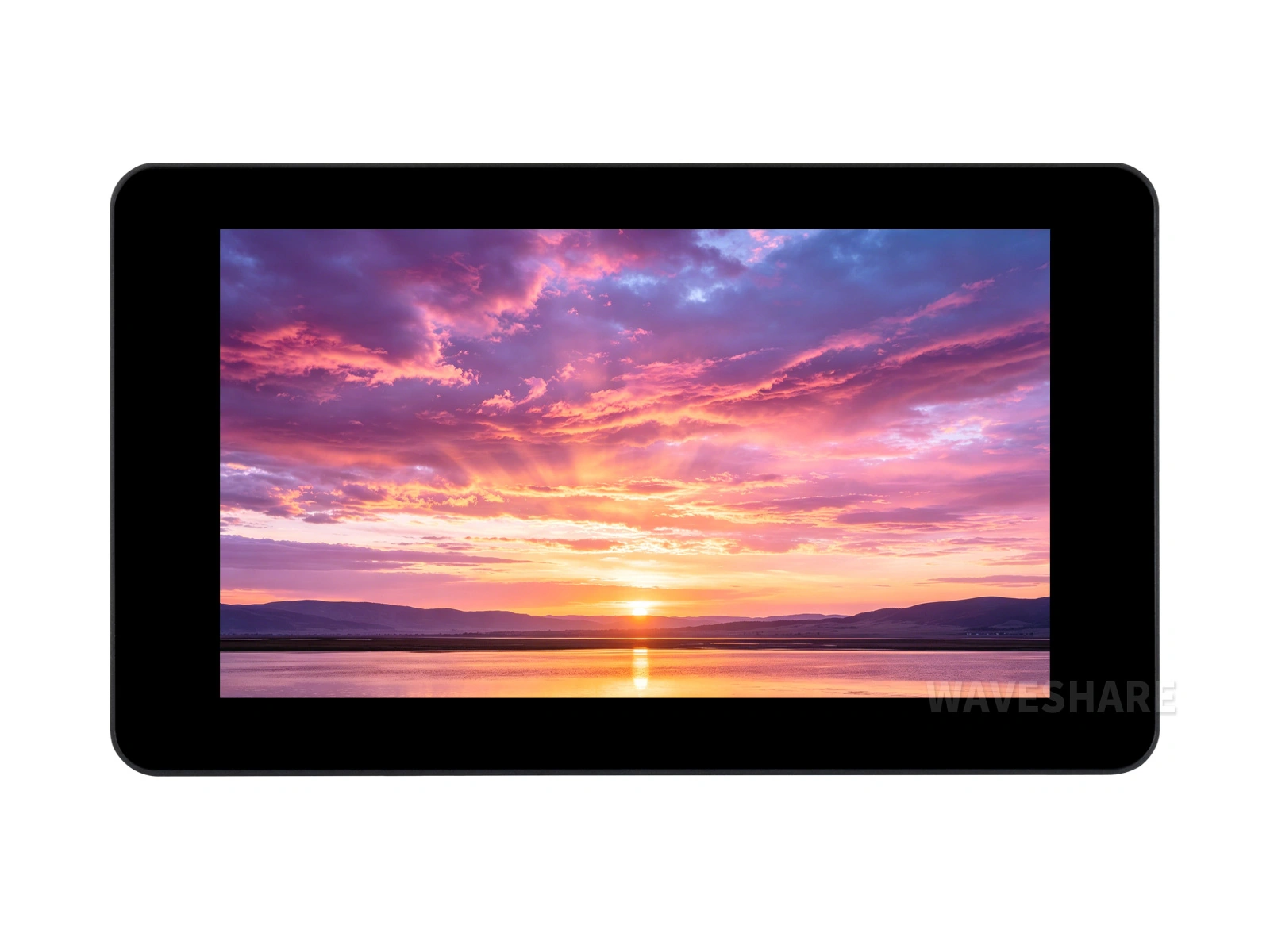
Product Introduction
Product Overview
This is a microcontroller development board designed by Waveshare, supporting 2.4GHz Wi-Fi and BLE 5, integrating Flash and PSRAM, and featuring an onboard 7inch capacitive touch LCD screen capable of running GUI programs such as LVGL. It provides a variety of peripheral interfaces for HMI and related application development with the ESP32-S3. The audio section offers both 3.5mm and MX1.25 audio connectors, with an onboard ES8389 audio codec and ES7210 audio capture chip for speaker output and microphone capture.
| SKU | Product |
|---|---|
| 34894 | ESP32-S3-Touch-LCD-7C-BOX |
Features
- Equipped with Xtensa 32-bit LX7 dual-core processor, main frequency up to 240MHz
- Supports 2.4 GHz Wi-Fi (802.11 b/g/n) and Bluetooth 5 (LE) with an onboard antenna
- Built-in 512KB SRAM and 384KB ROM, stacked with 32MB Flash and 16MB PSRAM
- Onboard 7inch LCD capacitive touchscreen, 800 × 480 resolution, 65K colors
- Supports I2C interface control for capacitive touch, with 5-point touch, and supports interrupts
- Onboard ES8389 audio codec and ES7210 echo cancellation circuit
- Onboard voltage regulator, supporting 7 ~ 36V wide-voltage power supply
- Onboard RTC chip and battery holder, retaining time after power-off when a battery is installed
- Onboard BQ27220 fuel gauge for real-time battery capacity monitoring
- Onboard I2C interface, TF card slot, PH2.0 battery connector
- Onboard LED indicators for power status, battery charging status, and a user-definable STA status LED
- Supports flexible clock and independent power supply settings for precise control, enabling low-power modes in various scenarios
Onboard Resources
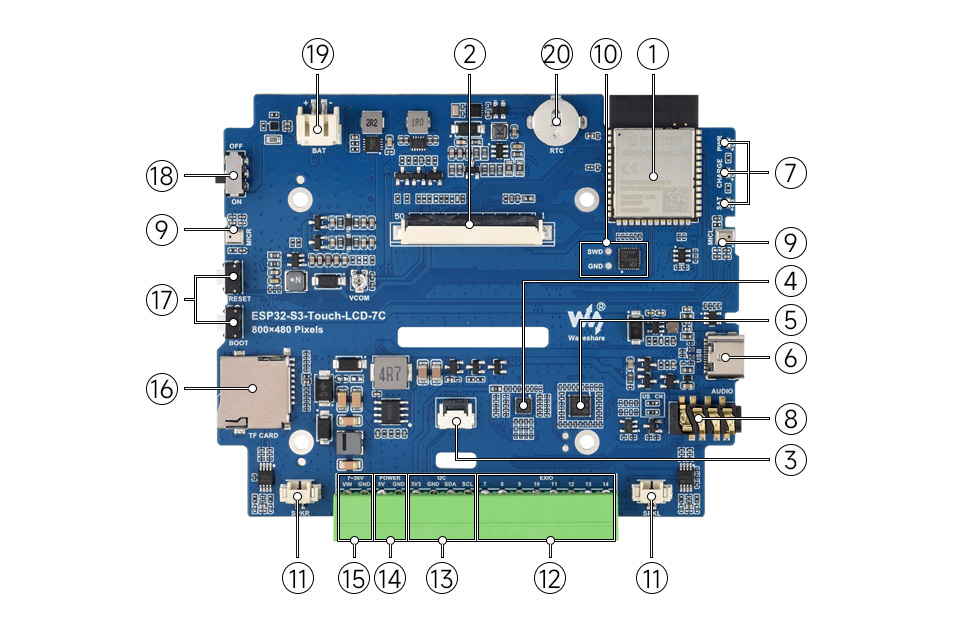
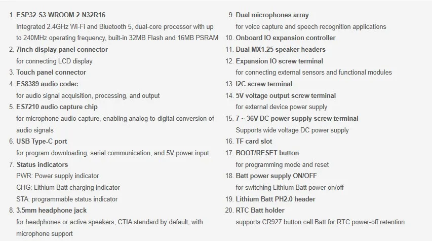
Interface Description
When using the ESP32-S3-Touch-LCD-7C, it's important to understand the hardware connections for different peripherals.
LCD Interface: Connector for the LCD cable (click to expand)
| ESP32-S3 | LCD | Description |
|---|---|---|
| GPIO0 | G3 | Green data bit 3 |
| GPIO1 | R3 | Red data bit 3 |
| GPIO2 | R4 | Red data bit 4 |
| GPIO3 | VSYNC | Vertical sync signal |
| GPIO5 | DE | Data enable signal |
| GPIO7 | PCLK | Pixel clock signal |
| GPIO8 | G6 | Green data bit 6 |
| GPIO9 | G5 | Green data bit 5 |
| GPIO10 | B7 | Blue data bit 7 |
| GPIO14 | B3 | Blue data bit 3 |
| GPIO17 | B6 | Blue data bit 6 |
| GPIO18 | B5 | Blue data bit 5 |
| GPIO21 | G7 | Green data bit 7 |
| GPIO38 | B4 | Blue data bit 4 |
| GPIO39 | G2 | Green data bit 2 |
| GPIO40 | R7 | Red data bit 7 |
| GPIO41 | R6 | Red data bit 6 |
| GPIO42 | R5 | Red data bit 5 |
| GPIO45 | G4 | Green data bit 4 |
| GPIO46 | HSYNC | Horizontal sync signal |
| IO EXTENSION | LCD | - |
| EXIO0 | LCD_RST | LCD reset pin |
| EXIO2 | DISP | Backlight enable pin |
| EXIO5 | LCD_VDD_EN | VCOM voltage enable pin |
Touch Interface: Connects to the touch cable (click to expand)
| ESP32-S3 | Touch | Description |
|---|---|---|
| GPIO4 | CTP_IRQ | Touch interrupt pin |
| GPIO47 | TP_SDA | Touch data pin |
| GPIO48 | TP_SCL | Touch clock pin |
| IO EXTENSION | Touch | - |
| EXIO1 | CTP_RST | Touch reset pin |
USB Interface: Used for power supply and flashing (click to expand)
| ESP32-S3 | USB | Description |
|---|---|---|
| GPIO19 | USB_DN | Data line D- |
| GPIO20 | USB_DP | Data line D+ |
TF Card Interface: Connects to the TF card (click to expand)
| ESP32-S3 | TF | Description |
|---|---|---|
| GPIO11 | MOSI | TF card input pin |
| GPIO12 | SCK | TF card clock pin |
| GPIO13 | MISO | TF card output pin |
| IO EXTENSION | TF | - |
| EXIO4 | SD_CS | TF card chip select pin, active low |
I2C Interface: Connects to the I/O expander chip, touch interface, and external interfaces (click to expand)
The ESP32-S3 provides multiple hardware I2C buses. Currently, GPIO47 (SDA) and GPIO48 (SCL) are used as the I2C bus.
Peripherals such as the I/O expander chip and touch screen are connected via this I2C interface.
| ESP32-S3 | I2C | Description |
|---|---|---|
| GPIO47 | SDA | I2C data pin |
| GPIO48 | SCL | I2C clock pin |
I2S Interface: Audio data transmission (click to expand)
The ESP32-S3 provides an I2S peripheral. This product uses I2S to connect the onboard audio codec and audio capture chip. Pin definitions can be found in speaker_microphone.h.
The I2S interface enables speaker playback and microphone recording data transfer.
| ESP32-S3 | I2S | Description |
|---|---|---|
| GPIO44 | I2S_SCLK | I2S clock pin |
| GPIO6 | I2S_MCLK | I2S master clock pin |
| GPIO16 | I2S_LCLK | I2S left/right channel clock pin |
| GPIO15 | I2S_DOUT | Speaker playback data output |
| GPIO43 | I2S_DSIN | Microphone input data |
| EXIO3 | PA_CTRL | Speaker enable pin |
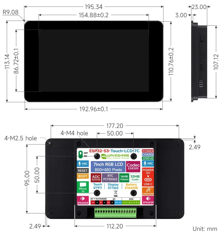
Dimensions
Specifications
Screen Parameters
| Item | Specification |
|---|---|
| Resolution | 800 × 480 |
| Display Color | 65K colors |
| Display Interface | RGB |
| Display Panel | IPS |
| Viewing Angle | 170° |
| Touch Type | Capacitive |
| Touch Panel | Tempered Glass |
Peripheral Interfaces and Others
| Item | Specification |
|---|---|
| Communication Interfaces | I2C, USB |
| Audio Interfaces | MX1.25, 3.5mm |
| Product Dimensions (L×W) | 195.34 × 110.76mm |
Development Methods
The ESP32-S3-Touch-LCD-7C supports two development frameworks: Arduino IDE and ESP-IDF, providing developers with flexible choices. You can select the appropriate development tool based on project requirements and personal preference.
Arduino generally offers a gentler learning curve and may be more approachable for beginners and hobbyists. ESP-IDF provides advanced tooling and finer control over system behavior, making it better suited to complex projects and applications with demanding performance requirements.
-
Arduino IDE is a convenient, flexible, and easy-to-use open-source electronics prototyping platform. It requires minimal foundational knowledge, allowing for rapid development after a short learning period. Arduino has a huge global user community, providing a vast amount of open-source code, project examples, and tutorials, as well as a rich library ecosystem that encapsulates complex functions, enabling developers to implement various features rapidly. You can refer to the Working with Arduino to complete the initial setup, and the tutorial also provides related example programs for reference.
-
ESP-IDF, short for Espressif IoT Development Framework, is the development framework launched by Espressif Systems for its ESP series of chips. It is based on C language development and includes compilers, debuggers, flashing tools, etc. It supports development via command line or integrated development environments (such as Visual Studio Code with the Espressif IDF plugin), which provides features like code navigation, project management, and debugging. When developing with VS Code, refer to the Working with ESP-IDF for the specific configuration process, which also includes relevant example programs.