Working with Arduino
This chapter contains the following sections. Please read as needed:
Arduino Getting Started
New to Arduino ESP32 development and looking for a quick start? We have prepared a comprehensive Getting Started Tutorial for you.
- Section 0: Getting to Know ESP32
- Section 1: Installing and Configuring Arduino IDE
- Section 2: Arduino Basics
- Section 3: Digital Output/Input
- Section 4: Analog Input
- Section 5: Pulse Width Modulation (PWM)
- Section 6: Serial Communication (UART)
- Section 7: I2C Communication
- Section 8: SPI Communication
- Section 9: Wi-Fi Basics
- Section 10: Web Server
- Section 11: Bluetooth
- Section 12: LVGL GUI Development
- Section 13: Comprehensive Project
Note: This tutorial uses the ESP32-S3-Zero as a reference example, and all hardware code is based on its pinout. Before you start, we recommend checking the pinout of your development board to ensure the pin configuration is correct.
Setting Up the Development Environment
1. Installing and Configuring the Arduino IDE
- Please refer to the Arduino IDE Installation and Configuration Tutorial to download and install the Arduino IDE and add ESP32 board support.
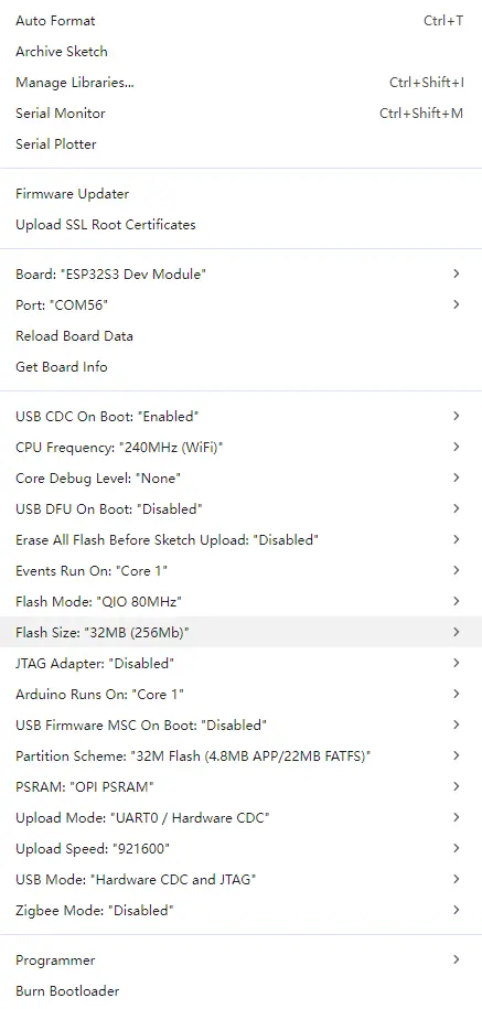
2. Selecting Board and Port
- After connecting the ESP32-S3-Touch-LCD-7C to your computer, select the corresponding serial port in the "Tools" menu.
3. Example Code Package and Libraries
- The Arduino example programs and required library files for the ESP32-S3-Touch-LCD-7C are included in the example code package.
- After extraction, the Arduino examples are located in the
Arduino/examplesdirectory, and the library files are in theArduino/librariesdirectory. You can add the libraries to the Arduino IDE following the general Arduino tutorial.
ESP32-S3-Touch-LCD-7C Board Installation Requirements
| Board Name | Installation Requirement | Version Requirement |
|---|---|---|
| ESP32 by Espressif Systems | "Offline" / "Online" installation | 3.5.5 |
| ESP32-audioI2S-master | "Online" installation | 3.4.6 |
| LVGL | "Online" installation | 8.4.0 |
Parameter Configuration
Example
| Example | Basic Description |
|---|---|
| 01_I2C | Test I2C interface communication |
| 02_RTC | Test RTC real-time clock functionality |
| 03_LCD | Test LCD display functionality |
| 04_ISOLATION_IO | Test isolated I/O functionality |
| 05_SD | Test TF card read/write functionality |
| 06_TOUCH | Test touchscreen functionality |
| 07_DISPLAY_BMP | Display BMP images |
| 08_BAT_INFO | Test battery information reading |
| 09_SPEAKER_MICROPHONE | Test speaker and microphone |
| 10_LVGL_CODEC | LVGL codec example |
01_I2C
Hardware Connection
- Connect the development board to a computer using a USB cable.
Code
I2C Backlight Control Code
void setup() {
  // Initialize the IO EXTENSION device for I2C communication.
  DEV_I2C_Init();
  IO_EXTENSION_Init();
  delay(10);
}

void loop() {
  // Turn on the LCD backlight by setting IO_EXTENSION_IO_2 high.
  IO_EXTENSION_Output(IO_EXTENSION_IO_2, 1);
  delay(500);  // Wait for 500 milliseconds.

  // Turn off the LCD backlight by setting IO_EXTENSION_IO_2 low.
  IO_EXTENSION_Output(IO_EXTENSION_IO_2, 0);
  delay(500);  // Wait for 500 milliseconds.
}
Code Analysis
DEV_I2C_Init(): Initializes the I2C bus in preparation for communication with the I/O expansion chip.IO_EXTENSION_Init(): Initializes the external I/O expansion chip.IO_EXTENSION_Output(IO_EXTENSION_IO_2, 1/0): ControlsIO_2to output high/low level, used to turn the LCD backlight on/off.delay(500): Controls the blinking rhythm of the backlight to make it easy to observe whether the output is normal.
Operation Result
- You will see the LCD backlight blinking.
02_RTC
Hardware Connection
- Connect the development board to a computer using a USB cable.
Code
RTC Time Reading Code
void loop() {
  // Read current time from RTC
  PCF85063A_Read_now(&Now_time);

  // Format current time as a string
  datetime_to_str(datetime_str, Now_time);
  printf("Now_time is %s\r\n", datetime_str);

  // Poll external IO pin for alarm (low level = alarm triggered)
  if (IO_EXTENSION_Rtc_Int_Read() == 0)
  {
      // Re-enable alarm if repeated alarms are required
      PCF85063A_Enable_Alarm();
      printf("The alarm clock goes off.\r\n");
  }

  delay(1000);  // Update every second
}
Code Analysis
PCF85063A_Read_now(&Now_time): Reads the current time from the PCF85063A RTC intoNow_time.datetime_to_str(datetime_str, Now_time): Converts the time structure to a string for easy output and display.printf("Now_time is %s..."): Outputs the current time via serial port to verify whether the RTC is working properly.IO_EXTENSION_Rtc_Int_Read() == 0: Reads the RTC interrupt pin state; low level indicates the alarm has triggered.PCF85063A_Enable_Alarm(): Re-enables the alarm after it triggers, facilitating repeated trigger tests.delay(1000): Updates the time and checks the alarm every second.
Operation Result
-
The RTC time is printed over the serial port.

03_LCD
Hardware Connection
- Connect the development board to a computer using a USB cable.
Code
LCD Display Test Code
      Paint_DrawString_EN(1, 70, "AaBbCc123", &Font16, RED, WHITE);
      Paint_DrawNum(1, 100, 9.87654321, &Font20, 7, WHITE, BLACK);
      Paint_DrawString_EN(1, 130, "AaBbCc123", &Font20, 0x000f, 0xfff0);
      Paint_DrawString_EN(1, 160, "AaBbCc123", &Font24, RED, WHITE);
      Paint_DrawString_CN(1, 190, "Hello Abc", &Font24CN, WHITE, BLUE);
Code Analysis
Paint_DrawString_EN(...): Draws an English string at the specified coordinates, with configurable font, foreground color, and background color.Paint_DrawNum(...): Draws a floating‑point number using the specified font and format parameters (used here to verify number rendering).Paint_DrawString_CN(...): Draws a Chinese string to verify Chinese font and display effects.
Operation Result
-
Test content is displayed on the screen.
-
You will see text, graphics, and image display effects.

04_ISOLATION_IO
Hardware Connection
- Connect the development board to a computer using a USB cable.
Operation Result
- After successful flashing, if all I/O connections are successful, the screen turns green; otherwise, it turns red.
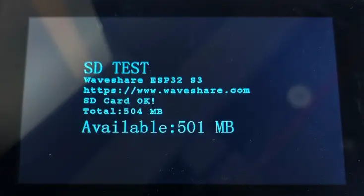
05_SD
Hardware Connection
- Connect the development board to a computer using a USB cable.
- Insert a TF card into the development board.
Code Analysis
setup():- Initialize the TF card.
loop():- Tests TF card read/write functionality.
Operation Result
-
The screen displays TF card information and test results.
06_TOUCH
Hardware Connection
- Connect the development board to a computer using a USB cable.
Code Analysis
setup():- Initializes the touchscreen.
loop():- Tests multi‑touch functionality.
Operation Result
- Touching the screen works normally.
- You will see touch points displayed on the screen.
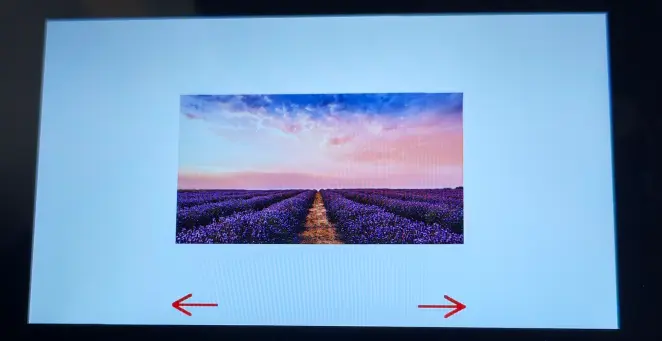
07_DISPLAY_BMP
Hardware Connection
- Connect the development board to a computer using a USB cable.
- Insert a TF card containing BMP images.
Code Analysis
setup():- Initializes the TF card and LCD.
loop():- Reads and displays BMP images.
Operation Result
-
BMP images are displayed on the screen.
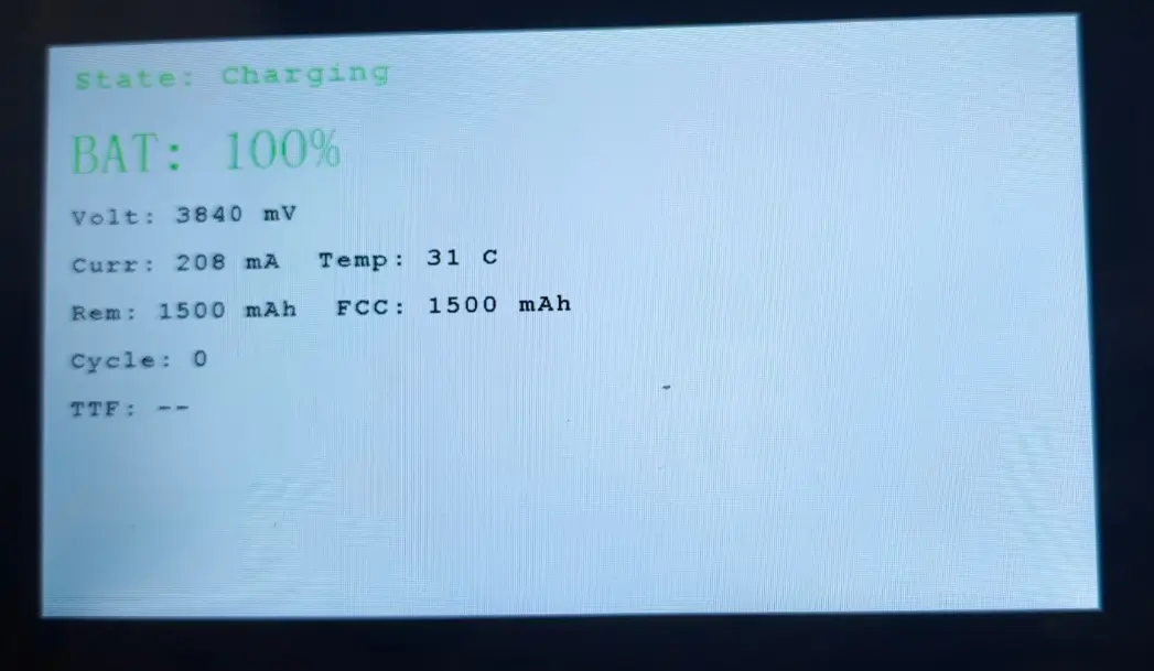
08_BAT_INFO
Hardware Connection
- Connect the development board to a computer using a USB cable.
- Connect a Lithium battery to the development board.
Code
Battery Information Reading Code
#define BATTERY_CAPACITY_MAH 1500

void setup()
{
    BatteryStatus bat_sta;

    Serial.begin(115200);
    DEV_I2C_Init();
    delay(100);

    bat_sta = battery_init(BATTERY_CAPACITY_MAH);

    IO_EXTENSION_Init();
    display_init();

    if (bat_sta == BATTERY_NOT_CONNECT) {
        display_show_not_connect();
    } else if (bat_sta != BATTERY_OK) {
        display_show_error(battery_status_to_string(bat_sta));
    }
}

void loop()
{
    BatteryInfo bat_info;
    BatteryStatus bat_sta;

    bat_sta = battery_get_info(&bat_info);
    if (bat_sta == BATTERY_OK) {
        display_show_info(&bat_info);
    } else if (bat_sta == BATTERY_NOT_CONNECT) {
        display_show_not_connect();
    } else {
        display_show_error(battery_status_to_string(bat_sta));
    }
    delay(1000);
}
Code Analysis
BATTERY_CAPACITY_MAH: Configures the nominal battery capacity for charge estimation and display.Serial.begin(115200): Initializes serial output for debugging.DEV_I2C_Init(): Initializes the I2C bus for communication with the fuel gauge and I/O expansion chip.battery_init(BATTERY_CAPACITY_MAH): Initializes the battery/fuel‑gauge module and returns the current battery status.IO_EXTENSION_Init()/display_init(): Initializes the I/O expansion and display modules in preparation for UI display.battery_get_info(&bat_info): Periodically reads battery information and stores it inbat_info.display_show_info(...)/display_show_not_connect()/display_show_error(...): Displays battery info, not‑connected prompt, or error message on the screen according to the read status.delay(1000): Refreshes the battery information display every second.
Operation Result
-
Battery information is displayed on the screen.
09_SPEAKER_MICROPHONE
Hardware Connection
- Connect the development board to a computer using a USB cable.
- Connect the speaker and microphone.
Code Analysis
setup():- Initializes the audio codec.
loop():- Tests audio input and output functionality.
Operation Result
-
You can record audio via the microphone and play it back through the speaker.

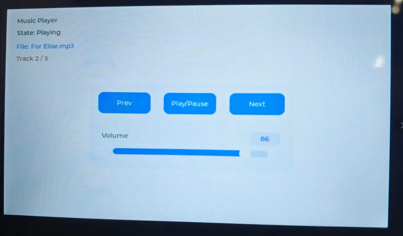
10_LVGL_CODEC
Hardware Connection
- Connect the development board to a computer using a USB cable.
Code Analysis
setup():- Initializes the LVGL graphics library.
loop():- Tests LVGL codec functionality.
Operation Result
-
The LVGL interface is displayed on the screen, and music can be played normally (a TF card must be inserted in advance).