ESP32-S3-ePaper-1.54G
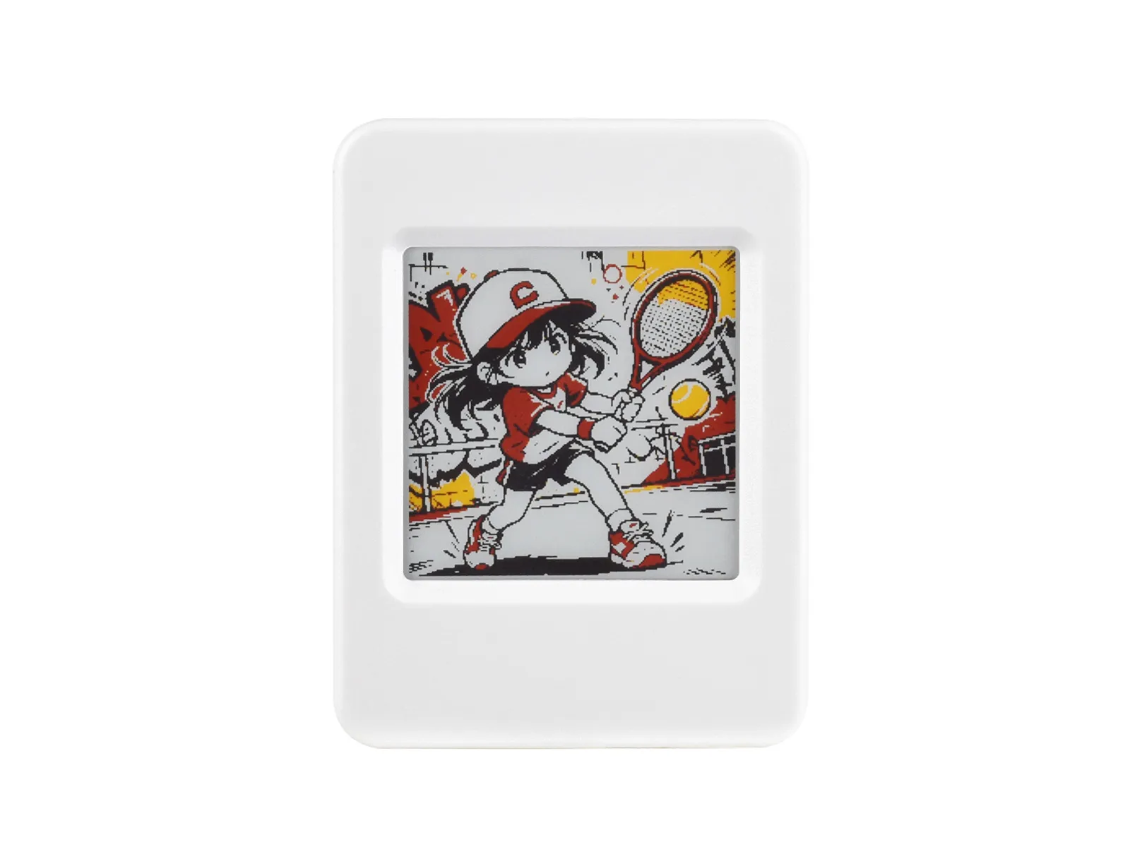
This product is an e-Paper AIoT development board featuring an ESP32-S3-PICO-1-N8R8 dual-core LX7 processor (240 MHz). It supports 2.4 GHz Wi-Fi and Bluetooth 5 (LE), features 512 KB onboard SRAM, with 8 MB PSRAM and 8 MB Flash stacked on-chip. The board comes with a 1.54inch e-Paper display, which offers ultra-low power consumption and excellent visibility under ambient light, making it ideal for portable devices and long-endurance applications. It integrates an RTC chip, SHTC3 temperature and humidity sensor, TF card slot, low-power audio codec chip circuit, and Lithium battery recharge management circuit. It reserves interfaces including USB, UART, I2C, and GPIO for easy functionality expansion and sensor connectivity, providing a flexible and reliable development platform for IoT terminals, electronic tags, portable displays, and other applications.
| SKU | Product |
|---|---|
| 34586 | ESP32-S3-ePaper-1.54G |
| 34585 | ESP32-S3-ePaper-1.54G-EN |
If you are looking for:
- Accelerating development with AI tools: Share this page link with AI tools to help them accurately understand the board hardware and generate usable code.
- Developing with Arduino IDE: See Working with Arduino
- Developing with ESP-IDF: See Working with ESP-IDF
- Downloading schematics, datasheets, and example code: See Related Resources
- Having issues: See Product FAQ or contact Technical Support
Onboard Resources
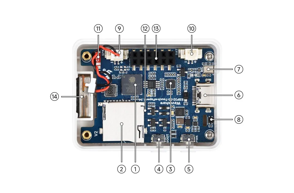
- ESP32-S3-PICO-1-N8R8 Wi-Fi and Bluetooth SoC, running at 240MHz, with integrated 8MB Flash and 8MB PSRAM in a stacked package
- TF Card Slot TF card must be formatted as FAT32 for use
- ES8311 Audio Codec Chip Supports audio input and output, low-power design, suitable for voice recognition and playback applications
- BOOT Button Press and hold the BOOT button to power on again to enter download mode
- PWR Power Button Hold BOOT, re-power on to enter download mode
- Type-C Interface ESP32-S3 USB interface for program flashing and serial logging
- Microphone For audio capture
- SHTC3 Temperature and Humidity Sensor Provides ambient temperature and humidity measurement, enabling environmental monitoring function
- MX1.25 2PIN Speaker Header Audio signal output, for connecting external speaker
- MX1.25 2PIN Lithium Battery Header For connecting a lithium battery
- Onboard Antenna Supports 2.4GHz Wi-Fi (802.11 b/g/n) and Bluetooth 5 (LE)
- PCF85063 (back side) RTC clock chip, supports time-keeping function
- 2 × 6PIN 2.54mm Pitch Female Header Can be used for expansion
- Speaker Plays audio
Peripheral Quick Reference
| Module | Device / Function | Interface | Address / Parameters | GPIO / Signals |
|---|---|---|---|---|
| E-Paper | 1.54G | SPI | 200 x 200 | EPD_PWR=GPIO6, EPD_BUSY=GPIO8, EPD_DC=GPIO10, EPD_CS=GPIO11, EPD_SCLK=GPIO12, EPD_SDI=GPIO13, EPD_RST=GPIO9 |
| RTC | PCF85063ATL | I2C | Common 7-bit address 0x51, 32.768 kHz crystal | SCL=GPIO48, SDA=GPIO47, INT=GPIO5 |
| Battery Sampling | VBAT divided to ADC | ADC | R21 pull-up 200K, R38 pull-down 200K; VBAT=VADC×2 | GPIO4 / BAT_ADC |
| Power Control | BAT_KEY / BAT_Control | GPIO | PWR power function circuit | BAT_KEY=GPIO18, BAT_Control=GPIO17 |
| Audio Capture/Playback | ES8311 | I2S | Common 7-bit address: 0x18 | I2S_MCLK=GPIO14, I2S_SCLK=GPIO15, I2S_ASDOUT=GPIO16, I2S_LRCK=GPIO38, I2S_DSDIN=GPIO45, PA_EN=GPIO42, PA_CTRL=GPIO46 |
| Temperature & Humidity Sensor | SHTC3 | I2C | Common 7-bit address: 0x70 | SCL=GPIO48, SDA=GPIO47 |
| TF Card | TF Card Slot | SDIO | SD_CLK=GPIO39, SD_MOSI=GPIO41, SD_MISO=GPIO40 | |
| USB Type-C | ESP32-S3 native USB | USB | Download, logging | USB_N=GPIO19, USB_P=GPIO20 |
| UART0 | Default serial port | UART | Debug / externally accessible interface | U0TXD=GPIO43, U0RXD=GPIO44 |
| Charging Management | ETA6098 | Power | Single-cell Li-Ion battery charging/discharging | GH1.25 battery connector |
| 3.3V DC-DC | MP1605 | Power | System 3.3V | VCC3V3 |
ePaper Display Specifications
| Display Panel | E-Paper | Display Size | 1.54inch |
|---|---|---|---|
| Display Resolution | 200 × 200 | Grayscale Levels | 2 |
| Communication Interface | SPI | Full Refresh Time | 20s |
| Display Colors | Red, Yellow, Black, White | Fast Refresh Time | 15s |
| Viewing Angle | >170° | Display Mode | Reflective |
Pinout Definition
When using the reserved GPIO terminals on the ESP32-S3-ePaper-1.54G board, pay attention to wire colors and corresponding functions to avoid damaging the board due to incorrect wiring habits
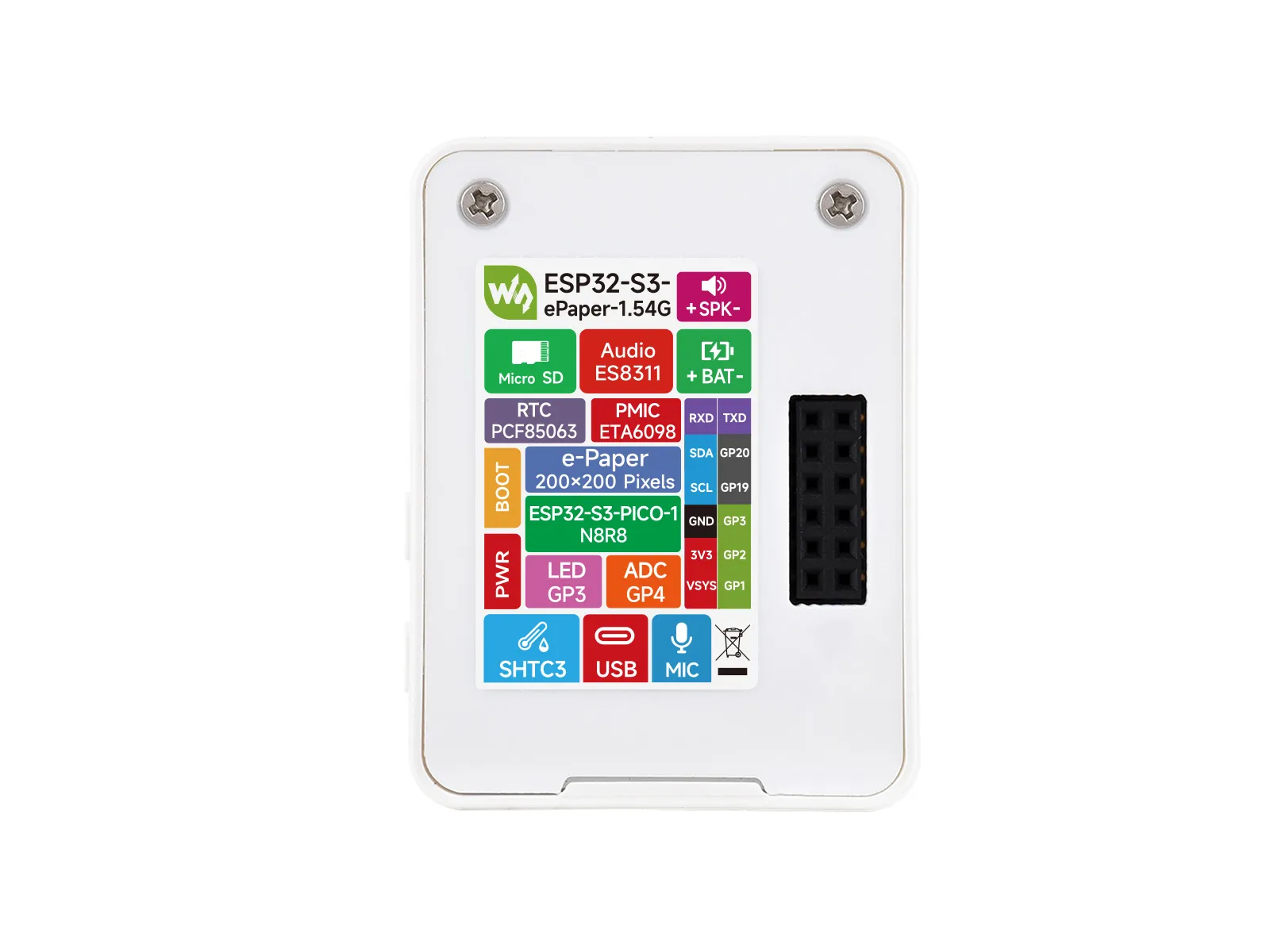
Expansion Interface
| Type | Signals |
|---|---|
| Power | 5V / 3V3 / GND |
| I2C | SCL(GPIO48) / SDA(GPIO47) |
| UART | TX(GPIO43) / RX(GPIO44) |
| USB | USB_N(GPIO19)/ USB_P(GPIO20) |
| GPIO | GPIO1 / GPIO2 / GPIO3 |
Full GPIO Allocation
The table below lists the GPIOs already occupied by onboard circuits and those brought out to expansion headers.
| GPIO | Signal Name | Connected To | Remarks |
|---|---|---|---|
| GPIO0 | BOOT / Key1 | BOOT button | Strapping pin; button to enter download mode |
| GPIO1 | GPIO1 | Reserved female header | Expansion header GPIO1 |
| GPIO2 | GPIO2 | Reserved female header | Expansion header GPIO2 |
| GPIO3 | GPIO3 | Reserved female header | Expansion header GPIO3 |
| GPIO4 | BAT_ADC | Battery voltage divider sampling | R21 pull-up 200K, R38 pull-down 200K; VBAT=VADC×2 |
| GPIO5 | RTC_INT | PCF85063 RTC interrupt | - |
| GPIO6 | EPD3V3_EN | E-Paper power switch | E-paper 3.3V supply enable |
| GPIO7 | EPD_TP_RST | Reserved touch for e-Paper | Touch reset pin (reserved) |
| GPIO8 | EPD_BUSY | E-Paper busy status | - |
| GPIO9 | EPD_RST | E-Paper reset | - |
| GPIO10 | EPD_D/C | E-Paper data/command | - |
| GPIO11 | EPD_CS | E-Paper chip select | SPI slave select |
| GPIO12 | EPD_SCLK | E-Paper SPI clock | SPI communication clock |
| GPIO13 | EPD_SDI | E-Paper SPI data | SPI master output data |
| GPIO14 | I2S_MCLK | ES8311 audio master clock | - |
| GPIO15 | I2S_SCLK | ES8311 audio bit clock | - |
| GPIO16 | I2S_ASDOUT | ES8311 audio data output | I2S audio output |
| GPIO17 | BAT_Control | Battery power control | Battery charge/discharge management |
| GPIO18 | BAT_KEY | Battery power enable switch | - |
| GPIO19 | USB_N | USB Type-C D- | ESP32-S3 native USB |
| GPIO20 | USB_P | USB Type-C D+ | ESP32-S3 native USB |
| GPIO21 | EPD_TP_INT | E-Paper touch interrupt | Touch interrupt (reserved) |
| GPIO38 | I2S_LRCK | ES8311 audio frame clock | - |
| GPIO39 | SD_CLK | TF card SDIO clock | - |
| GPIO40 | SD_MISO | TF card SDIO data 0 | - |
| GPIO41 | SD_MOSI | TF card SDIO command | - |
| GPIO42 | PA_EN | ES8311 power supply enable | - |
| GPIO43 | U0TXD | Reserved UART TX female header | Expansion header TX |
| GPIO44 | U0RXD | Reserved UART RX female header | Expansion header RX |
| GPIO45 | I2S_DSDIN | ES8311 audio data input | I2S audio capture |
| GPIO46 | PA_CTRL | Audio amplifier enable - | |
| GPIO47 | SDA | I2C data bus | Shared by RTC/SHTC3/ES8311/EPD_TP |
| GPIO48 | SCL | I2C clock bus | Shared by RTC/SHTC3/ES8311/EPD_TP |
Precautions
- When connecting external I2C devices, avoid address conflicts with
0x18,0x70,0x51. GPIO19/GPIO20are connected to USB Type-C and are not recommended for use as general-purpose GPIO.GPIO0is the BOOT pin, andEN/CHIP_PUis the reset signal; they are not recommended for general user input.GPIO33toGPIO37are used for the integrated Octal SPI PSRAM and cannot be used for other functions.
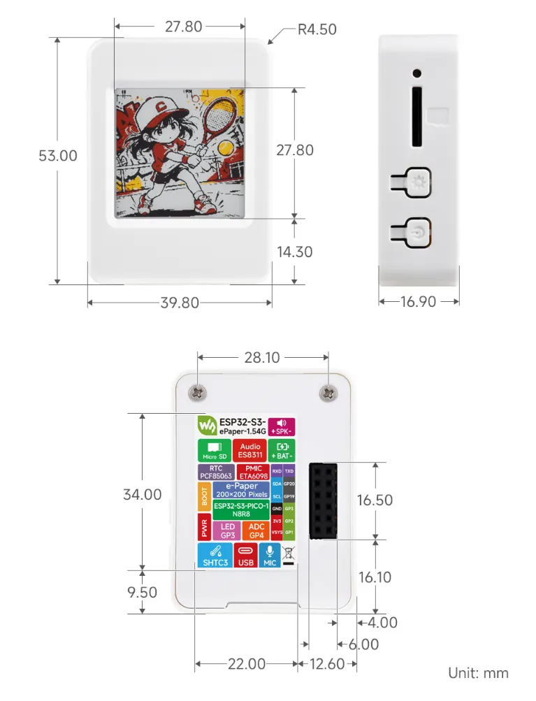
Dimensions
Development Methods
The ESP32-S3-ePaper-1.54G supports two development frameworks: Arduino IDE and ESP-IDF, offering flexibility for developers. You can choose the appropriate development tool based on project requirements and personal preference.
Both development methods have their own advantages. Developers can choose based on their needs and skill levels. Arduino is simple to learn and quick to start, suitable for beginners and non-professionals. ESP-IDF provides more advanced development tools and stronger control capabilities, suitable for developers with professional backgrounds or higher performance requirements, and is more appropriate for complex project development.
-
Arduino IDE is a convenient, flexible, and easy-to-use open-source electronics prototyping platform. It requires minimal foundational knowledge, allowing for rapid development after a short learning period. Arduino has a huge global user community, providing a vast amount of open-source code, project examples, and tutorials, as well as a rich library ecosystem that encapsulates complex functions, enabling developers to implement various features rapidly. You can refer to the Working with Arduino to complete the initial setup, and the tutorial also provides related example programs for reference.
-
ESP-IDF, short for Espressif IoT Development Framework, is a professional development framework launched by Espressif Systems for its ESP series of chips. It is based on C language development and includes compilers, debuggers, flashing tools, etc. It supports development via command line or integrated development environments (such as Visual Studio Code with the Espressif IDF plugin), which provides features like code navigation, project management, and debugging. We recommend using VS Code for development. For the specific configuration process, please refer to the Working with ESP-IDF. The tutorial also provides relevant example programs for reference.