Working with Arduino
This chapter contains the following sections. Please read as needed:
Arduino Getting Started
New to Arduino ESP32 development and looking for a quick start? We have prepared a comprehensive Getting Started Tutorial for you.
- Section 0: Getting to Know ESP32
- Section 1: Installing and Configuring Arduino IDE
- Section 2: Arduino Basics
- Section 3: Digital Output/Input
- Section 4: Analog Input
- Section 5: Pulse Width Modulation (PWM)
- Section 6: Serial Communication (UART)
- Section 7: I2C Communication
- Section 8: SPI Communication
- Section 9: Wi-Fi Basics
- Section 10: Web Server
- Section 11: Bluetooth
- Section 12: LVGL GUI Development
- Section 13: Comprehensive Project
Note: This tutorial uses the ESP32-S3-Zero as a reference example, and all hardware code is based on its pinout. Before you start, we recommend checking the pinout of your development board to ensure the pin configuration is correct.
Setting Up Development Environment
1. Installing and Configuring Arduino IDE
Please refer to the tutorial Installing and Configuring Arduino IDE to download and install the Arduino IDE and add ESP32 support.
Board Installation Instructions for ESP32-S3-ePaper-13.3E6
| Board Name | Installation Requirement | Version Requirement |
|---|---|---|
| ESP32 by Espressif Systems | "Install Offline" / "Install Online" | 3.2.0 |
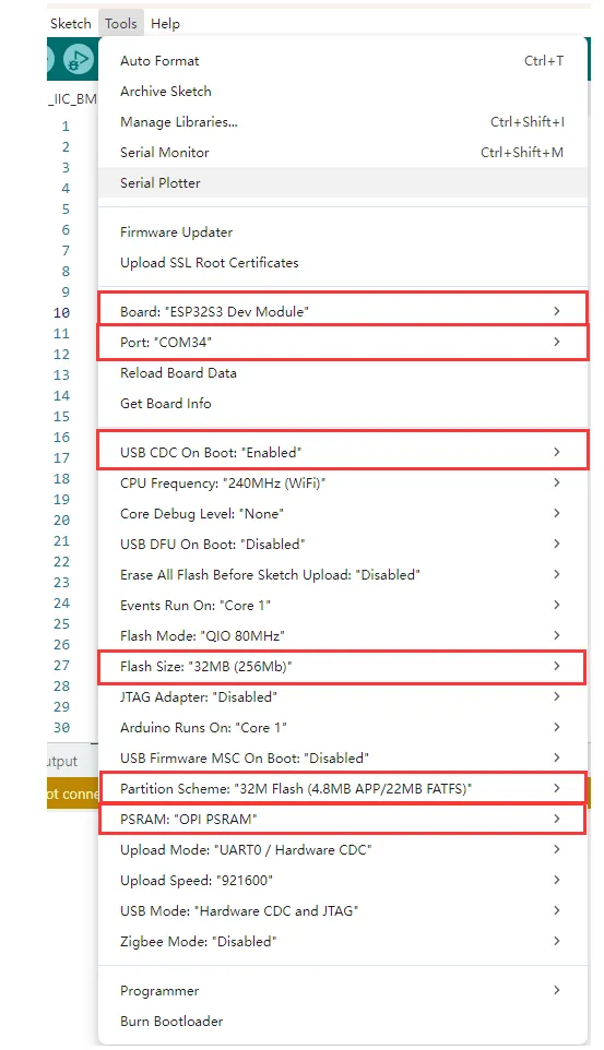
2. Arduino Project Parameter Settings
Example
The Arduino examples are located in the Arduino/examples directory of the example package.
| Example | Basic Program Description | Dependency Library |
|---|---|---|
| 01_ADC_Test | Get the voltage value of the lithium battery | - |
| 02_Audio_out | Audio playback example | - |
| 03_E-Paper_Example | 13.3inch e-Paper E6 e-paper screen example program | - |
| 04_SD_Test | Read TF card and display images | - |
| 05_Loader_esp32wf | WiFi image transfer example | - |
01_ADC_Test
Example Description
- The analog voltage connected through the GPIO is converted to digital by the ADC, and then the actual lithium battery voltage is calculated and printed to the terminal.
Hardware Connection
- Connect the board to the computer using a USB cable
Code Analysis
adc_bsp_init(void): Initializes ADC1, including creating an ADC one-shot trigger unit and configuring Channel 7 of ADC1.adc_get_value(float *value,int *data): Reads the value from Channel 7 of ADC1, calculates the corresponding voltage based on the reference voltage and resolution, and stores it at the location pointed to by the passed pointer. Stores 0 if the read fails.adc_example(void* parameter): After initializing ADC1, creates an ADC task. This task reads the ADC value every second and calculates the system voltage from the raw ADC reading.
Operation Result
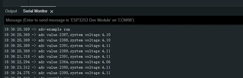
- After the program is compiled and downloaded, you can view the printed ADC values and voltage output by opening the Serial Monitor, as shown in the following image:
02_Audio_out
Example Description
- This example drives the ES8311 audio codec to play music.
Hardware Connection
- Connect the board to the computer using a USB cable
Code Analysis
-
Configure and initialize the ES8311 audio codec.
void setup() {Serial.begin(115200);Wire.begin(I2C_SDA, I2C_SCL);pinMode(PA_CTRL, OUTPUT);digitalWrite(PA_CTRL, HIGH);es8311_codec_init();setupI2S();Serial.println("I2S Initialized");} -
Continuously write built-in audio data to the I2S bus for looped playback.
i2s.write((uint8_t *)audio_data, AUDIO_SAMPLES * 2);
Operation Result
- The device will play the auido directly without showing content on the screen
03_E-Paper_Example
Example Description
- This is a local Arduino example for the 13.3inch E6 e-Paper screen. It performs e-Paper initialization, clears the screen, displays images, and draws basic graphics and text.
Hardware Connection
- Connect the board to the computer using a USB cable
Code Analysis
-
Display a predefined image.
#if 1 // show bmpprintf("show bmp1-----------------\r\n");EPD_13IN3E_Display(Image6color);DEV_Delay_ms(3000);#endif -
Draw basic shapes, Chinese/English text, numbers, and refresh the display.
#if 1 // Drawing on the imagePaint_NewImage(Image, EPD_13IN3E_WIDTH, EPD_13IN3E_HEIGHT, 90, EPD_13IN3E_WHITE);Paint_SetScale(6);//1.Select Imageprintf("SelectImage:Image\r\n");Paint_SelectImage(Image);Paint_Clear(EPD_13IN3E_WHITE);// 2.Drawing on the imageprintf("Drawing:Image\r\n");Paint_DrawPoint(10, 80, EPD_13IN3E_RED, DOT_PIXEL_1X1, DOT_STYLE_DFT);Paint_DrawPoint(10, 90, EPD_13IN3E_BLUE, DOT_PIXEL_2X2, DOT_STYLE_DFT);Paint_DrawPoint(10, 100, EPD_13IN3E_GREEN, DOT_PIXEL_3X3, DOT_STYLE_DFT);Paint_DrawLine(20, 70, 70, 120, EPD_13IN3E_YELLOW, DOT_PIXEL_1X1, LINE_STYLE_SOLID);Paint_DrawLine(70, 70, 20, 120, EPD_13IN3E_YELLOW, DOT_PIXEL_1X1, LINE_STYLE_SOLID);Paint_DrawRectangle(20, 70, 70, 120, EPD_13IN3E_BLACK, DOT_PIXEL_1X1, DRAW_FILL_EMPTY);Paint_DrawRectangle(80, 70, 130, 120, EPD_13IN3E_BLACK, DOT_PIXEL_1X1, DRAW_FILL_FULL);Paint_DrawCircle(45, 95, 20, EPD_13IN3E_BLACK, DOT_PIXEL_1X1, DRAW_FILL_EMPTY);Paint_DrawCircle(105, 95, 20, EPD_13IN3E_WHITE, DOT_PIXEL_1X1, DRAW_FILL_FULL);Paint_DrawLine(85, 95, 125, 95, EPD_13IN3E_YELLOW, DOT_PIXEL_1X1, LINE_STYLE_DOTTED);Paint_DrawLine(105, 75, 105, 115, EPD_13IN3E_YELLOW, DOT_PIXEL_1X1, LINE_STYLE_DOTTED);Paint_DrawString_CN(10, 130, "你好 abc", &Font12CN, EPD_13IN3E_BLACK, EPD_13IN3E_WHITE);Paint_DrawString_CN(10, 150, "微雪电子", &Font24CN, EPD_13IN3E_WHITE, EPD_13IN3E_BLACK);Paint_DrawNum(10, 33, 123456789, &Font12, EPD_13IN3E_BLACK, EPD_13IN3E_WHITE);Paint_DrawNum(10, 50, 987654321, &Font16, EPD_13IN3E_WHITE, EPD_13IN3E_BLACK);Paint_DrawString_EN(145, 0, "Waveshare", &Font16, EPD_13IN3E_BLACK, EPD_13IN3E_WHITE);Paint_DrawString_EN(145, 35, "Waveshare", &Font16, EPD_13IN3E_GREEN, EPD_13IN3E_WHITE);Paint_DrawString_EN(145, 70, "Waveshare", &Font16, EPD_13IN3E_BLUE, EPD_13IN3E_WHITE);Paint_DrawString_EN(145, 105, "Waveshare", &Font16, EPD_13IN3E_RED, EPD_13IN3E_WHITE);Paint_DrawString_EN(145, 140, "Waveshare", &Font16, EPD_13IN3E_YELLOW, EPD_13IN3E_WHITE);printf("EPD_Display\r\n");EPD_13IN3E_Display(Image);DEV_Delay_ms(3000);#endif
Operation Result
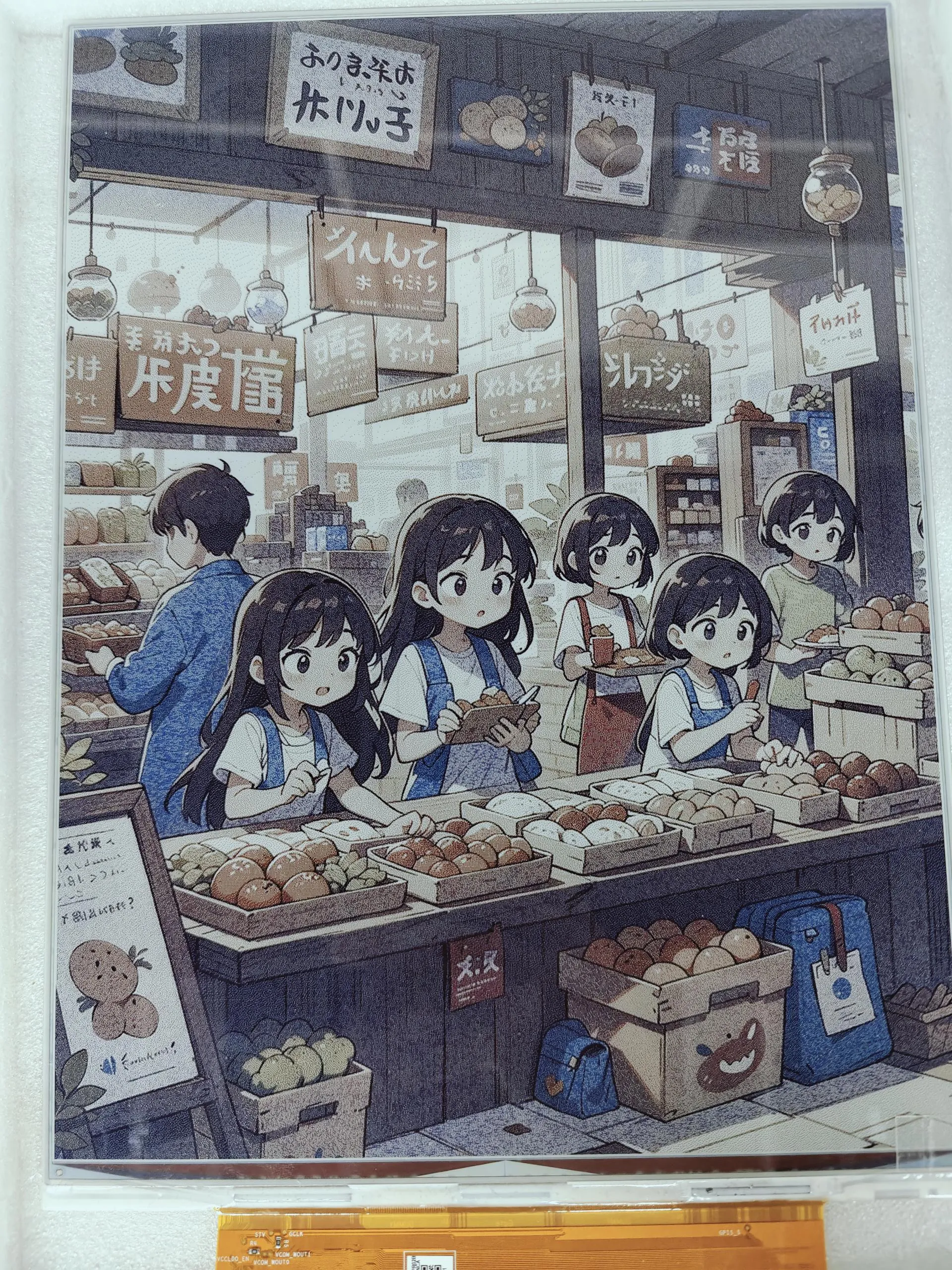
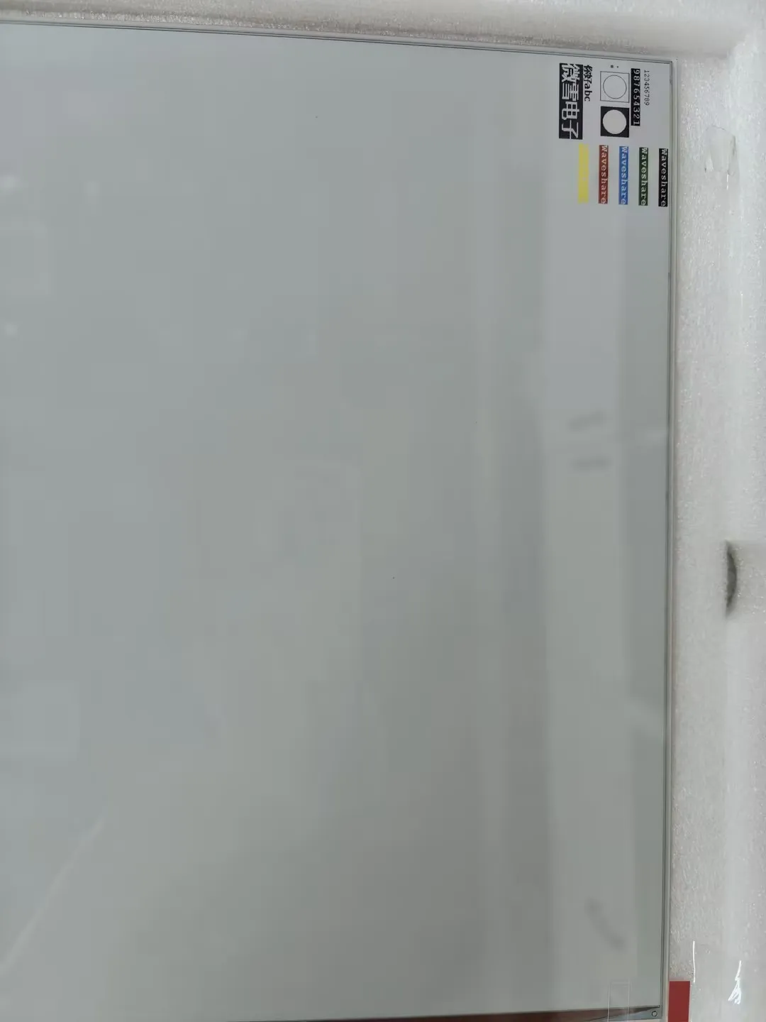
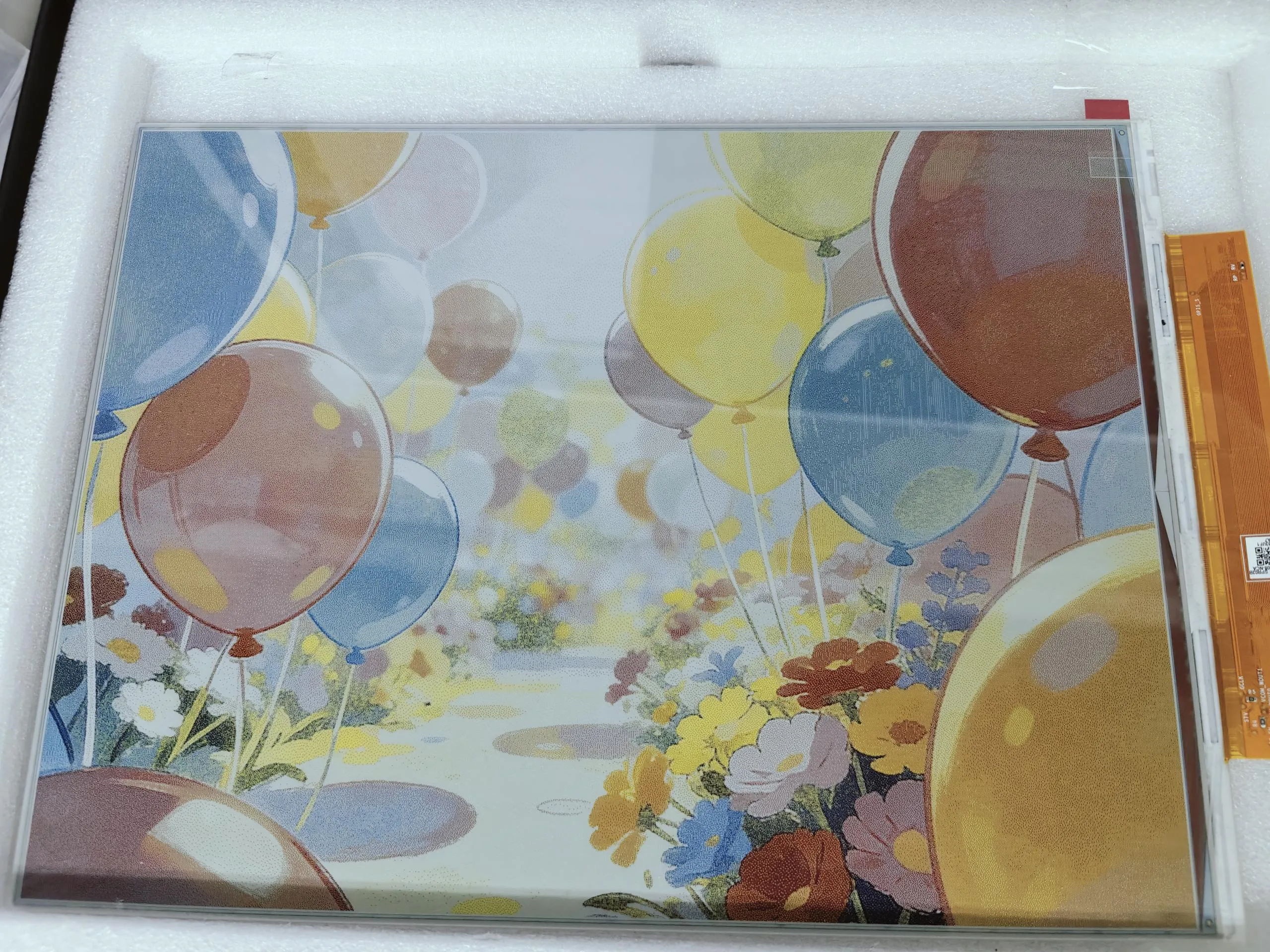
- The screen refreshes, clears, displays an image, and draws basic graphics and text.
04_SD_Test
Example Description
- This example reads BMP images from a TF card and refreshes them on the e-Paper display.
Hardware Connection
- Connect the board to the computer using a USB cable
- Insert the TF card module with a TF card containing a bmp folder with images in the root directory.
Code Analysis
-
Configure and mount the TF card.
//sdcard initSerial.begin(115200);delay(1000);SD_MMC.setPins(SD_CLK, SD_CMD, SD_D0, SD_D1, SD_D2, SD_D3);if (!SD_MMC.begin( "/sdcard", true)) {printf("TF card failed to mount\r\n");return;}printf("TF card success to mount\r\n"); -
Read .bmp images from the bmp folder on the TF card.
Serial.println("Scan the root directory BMP file...");File rootDir = SD_MMC.open("/bmp");if (rootDir && rootDir.isDirectory()) {File file = rootDir.openNextFile();while (file && bmpFileCount < 32) {if (!file.isDirectory()) {String fileName = file.name();String fullPath = file.path();fileName.toLowerCase();if (fileName.endsWith(".bmp")) {bmpFilePaths[bmpFileCount++] = MOUNT_POINT + fullPath;Serial.printf("find BMP:%s\n", fullPath.c_str());}}file.close();file = rootDir.openNextFile();}rootDir.close();}else{Serial.println("error : failed to open the root directory!");}
Operation Result
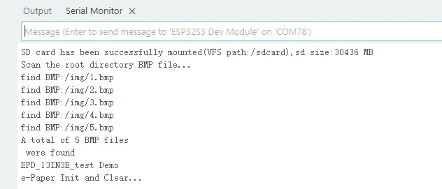
- Serial port prints TF card information.
- Reads and displays images from the TF card.
05_Loader_esp32wf
Example Description
- WiFi example
warning
This module only supports the 2.4GHz network band.
Hardware Connection
- Connect the board to the computer using a USB cable
Code Modification
-
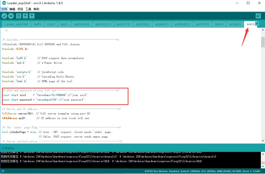
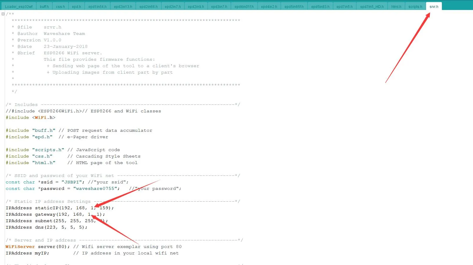
Open the
srvr.hfile and change thessidandpasswordto the actual WiFi username and password being used.infoModify the Wi-Fi username and password at this location to your own router's or mobile hotspot's Wi-Fi credentials. In this program, the ESP32 acts as a client (slave), not an access point; it does not broadcast its own Wi-Fi hotspot.
-
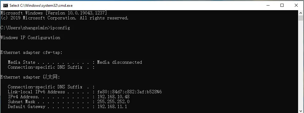
Press
Win + R, typeCMD, and open the command prompt to obtain the computer's IP address.
-
Open the
srvr.h fileand modify the network segment shown in the image to match your network segment.warningThe ESP32's IP address (the last octet) must be different from the computer's IP address, but the other three octets must be exactly the same.
-
Then click Upload to compile and download the program to the ESP32 driver board.
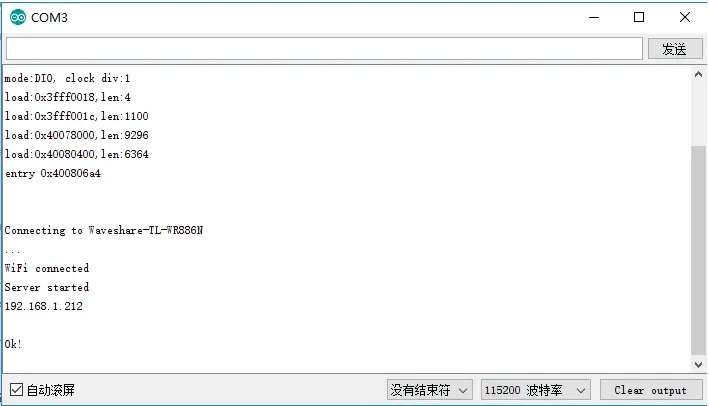
-
Open the Serial Monitor, set the baud rate to 115200, and you will see the ESP32's IP address printed:
-
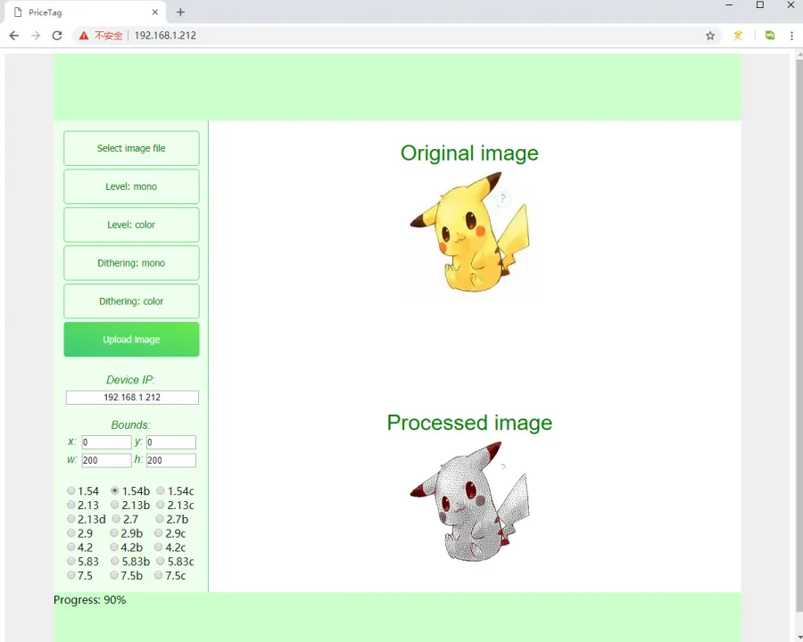
On a computer or mobile phone (ensure the device is connected to the same WiFi network as the ESP32), open a browser, enter the ESP32's IP address in the address bar, and open it. The operation interface will appear as shown below:
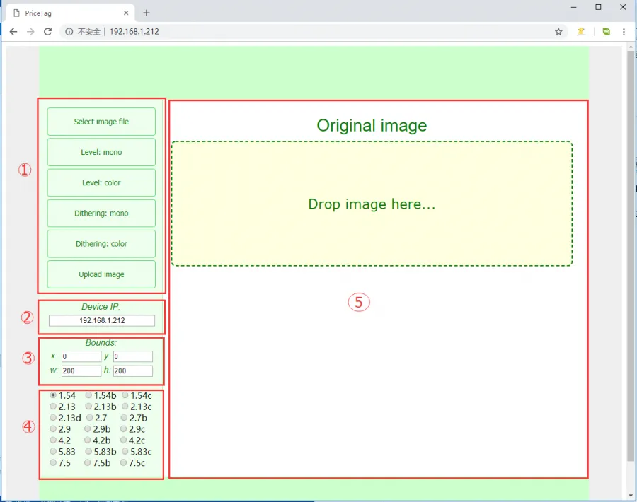
-
The interface is divided into five areas: Image Operation Area:
Select Image file: Click to select an image from the computer or phoneLevel: mono: Black-and-white color-level image processing algorithmLevel: color: Multi-color color-level image processing algorithm (effective only for multi-color screens)Dithering: mono: Black-and-white dithering image processing algorithmDithering: color: Multi-color dithering image processing algorithm (effective only for multi-color screens)Update image: Upload the image- IP Information Display Area: Shows the IP address of the currently connected module
- Image Size Setting Area: Here x and y set the starting position for display, relative to the selected image file. For example, if you select an 800x480 image but the connected e-Paper screen is 2.9 inches, the screen cannot display the whole image. The algorithm automatically crops a portion starting from the top-left corner. Setting x and y allows you to customize the starting crop position. w and h are the resolution of the current e-Paper screen. W and h represent the resolution of the current e-Paper screen.
warningIf you change the x and y values, you need to click the processing algorithm button again to regenerate the image.
- Model Selection Area: Here you can select the model of the connected e-Paper screen
- Image Display Area: Shows the selected image and the processed result
infoWhile uploading an image, the progress will be shown at the bottom.
-
In area ①, click
Select image fileto choose an image, or simply drag and drop an image into theOriginal imagearea. -
In area ④, select the corresponding e-Paper screen model, e.g.,
13.3E -
In area ①, click an image processing algorithm, e.g.,
Dithering: color -
In area ①, click
Upload imageto upload the image and display it on the e-paper screen.