ESP-IDF
This chapter contains the following sections. Please read as needed:
ESP-IDF Getting Started
New to ESP32 ESP-IDF development and looking to get started quickly? We have prepared a general Getting Started Tutorial for you.
- Section 1: Environment Setup
- Section 2: Running Examples
- Section 3: Creating a Project
- Section 4: Using Components
- Section 5: Debugging
- Section 6: FreeRTOS
- Section 7: Peripherals
- Section 8: Wi-Fi Programming
- Section 9: BLE Programming
Please Note: This tutorial uses the ESP32-S3-Zero as a teaching example, and all hardware code is based on its pinout. Before you start, it is recommended that you check the pinout of your development board to ensure the pin configuration is correct.
Setting Up Development Environment
For the ESP32-S3-ePaper-Driver-Board development board, ESP-IDF version V5.5.0 or above is required.
The following guide uses Windows as an example, demonstrating development using VS Code + the ESP-IDF extension. macOS and Linux users should refer to the official documentation.
The screenshots in this section use ESP-IDF V5.5.2 as an example. When installing, please select the ESP-IDF version that matches your board's example.
Install the ESP-IDF Development Environment
-
Download the installation manager from the ESP-IDF Installation Manager page. This is Espressif's latest cross-platform installer. The following steps demonstrate how to use its offline installation feature.
Click the Offline Installer tab on the page, then select Windows as the operating system and the ESP-IDF version you need (the version shown in the screenshot is for reference only — choose the version that fits your actual needs).

After confirming your selection, click the download button. The browser will automatically download two files: the ESP-IDF Offline Package (.zst) and the ESP-IDF Installer (.exe).

Please wait for both files to finish downloading.
-
Once the download is complete, double-click to run the ESP-IDF Installer (eim-gui-windows-x64.exe).
The installer will automatically detect if the offline package exists in the same directory. Click Install from archive.

Next, select the installation path. We recommend using the default path. If you need to customize it, ensure the path does not contain Chinese characters or spaces. Click Start installation to proceed.

-
When you see the following screen, the ESP-IDF installation is successful.

-
We recommend installing the drivers as well. Click Finish installation, then select Install driver.

Install Visual Studio Code and the ESP-IDF Extension
-
Download and install Visual Studio Code.
-
During installation, it is recommended to check Add "Open with Code" action to Windows Explorer file context menu to facilitate opening project folders quickly.
-
In VS Code, click the Extensions icon
 in the Activity Bar on the side (or use the shortcut Ctrl + Shift + X) to open the Extensions view.
 -
Enter ESP-IDF in the search box, locate the ESP-IDF extension, and click Install.

-
For ESP-IDF extension versions ≥ 2.0, the extension will automatically detect and recognize the ESP-IDF environment installed in the previous steps, requiring no manual configuration.
Example
The ESP-IDF examples are located in the ESP-IDF directory of the example package.
| Example | Basic Description |
|---|---|
| 01_ADC_Test | Get the lithium battery voltage value |
| 02_Mic_test | Play microphone recording through the speaker |
| 03_Music | Mount TF card and read/play music files from it |
| 04_E-Paper_Example | e-Paper example program |
| 05_SD_Test | Read TF card and display images |
| 06_xiaozhi-esp32 | Xiaozhi AI application |
01_ADC_Test
Example Description
- The analog voltage connected through the GPIO is converted to digital by the ADC, and then the actual lithium battery voltage is calculated and printed to the terminal.
Hardware Connection
- Connect the board to the computer using a USB cable
Code Analysis
adc_bsp_init(void): Initializes ADC1, including creating an ADC one-shot trigger unit and configuring Channel 7 of ADC1.adc_get_value(float *value,int *data): Reads the value from Channel 7 of ADC1, calculates the corresponding voltage based on the reference voltage and resolution, and stores it at the location pointed to by the passed pointer. Stores 0 if the read fails.adc_example(void* parameter): After initializing ADC1, creates an ADC task. This task reads the ADC value every second and calculates the system voltage from the raw ADC reading.
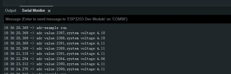
Operation Result
- After the program is compiled and downloaded, you can view the printed ADC values and voltage output by opening the Serial Monitor, as shown in the following image:
02_Mic_test
Example Description
- Demonstrates how to get data from the microphone and then play it through the speaker
Hardware Connection
- Connect the development board to the computer
Code Analysis
i2c_master_Init();: Initializes the I2C bus.user_ui_init();: Initializes the global UI.user_button_init();: Initializes the audio interface.
Operation Result
-
The screen shows nothing.
-
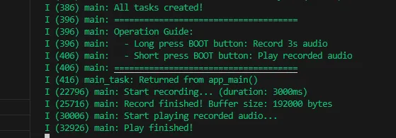
Long press the BOOT button to enter recording mode. Speak into the MIC, and it will automatically stop after 3 seconds.
-
Click the BOOT button to play the recorded sound. (If no recording exists, the played sound will be very harsh.)
-
Serial port prints:
03_Music
Example Description
- Mounts a TF card and reads/plays audio files from it.
Hardware Connection
- Connect the development board to the computer
- Connect a speaker to the SPK interface.
Code Analysis
_sdcard_init();: Initializes the TF card and reads the audio files from it.i2c_master_init();: Initializes the I2C bus, providing a communication link for configuration command transmission to the ES8311 audio codec.audio_player_play(audio_fp);: Starts the audio player, reads the opened MP3 file, and drives the speaker through the ES8311 for playback.
Operation Result
- The screen shows nothing.
- The speaker plays audio.
04_E-Paper_Example
Example Description
- This is a local ESP-IDF example for the 13.3inch E6 e-Paper screen. It performs e-Paper initialization, clears the screen, displays images, and draws basic graphics and text.
Hardware Connection
- Connect the development board to the computer
Code Analysis
-
Display a predefined image:
#if 1EPD_Display(Image6color);vTaskDelay(pdMS_TO_TICKS(3000));#endif -
Draw basic shapes, Chinese/English text, numbers, and refresh the display:
#if 1Paint_NewImage(Image_Mono, EPD_WIDTH, EPD_HEIGHT, 90, EPD_WHITE);Paint_SetScale(6);printf("SelectImage:Image\r\n");Paint_SelectImage(Image_Mono);Paint_Clear(EPD_WHITE);Paint_DrawPoint(10, 80, EPD_RED, DOT_PIXEL_1X1, DOT_STYLE_DFT);Paint_DrawPoint(10, 90, EPD_BLUE, DOT_PIXEL_2X2, DOT_STYLE_DFT);Paint_DrawPoint(10, 100, EPD_GREEN, DOT_PIXEL_3X3, DOT_STYLE_DFT);Paint_DrawLine(20, 70, 70, 120, EPD_YELLOW, DOT_PIXEL_1X1, LINE_STYLE_SOLID);Paint_DrawLine(70, 70, 20, 120, EPD_YELLOW, DOT_PIXEL_1X1, LINE_STYLE_SOLID);Paint_DrawRectangle(20, 70, 70, 120, EPD_BLACK, DOT_PIXEL_1X1, DRAW_FILL_EMPTY);Paint_DrawRectangle(80, 70, 130, 120, EPD_BLACK, DOT_PIXEL_1X1, DRAW_FILL_FULL);Paint_DrawCircle(45, 95, 20, EPD_BLACK, DOT_PIXEL_1X1, DRAW_FILL_EMPTY);Paint_DrawCircle(105, 95, 20, EPD_WHITE, DOT_PIXEL_1X1, DRAW_FILL_FULL);Paint_DrawLine(85, 95, 125, 95, EPD_YELLOW, DOT_PIXEL_1X1, LINE_STYLE_DOTTED);Paint_DrawLine(105, 75, 105, 115, EPD_YELLOW, DOT_PIXEL_1X1, LINE_STYLE_DOTTED);Paint_DrawString_CN(10, 130, "你好 abc", &Font16_UTF8, EPD_BLACK, EPD_WHITE);Paint_DrawString_CN(10, 170, "微雪电子", &Font16_UTF8, EPD_WHITE, EPD_BLACK);Paint_DrawNum(10, 10, 123456789, &Font12, EPD_BLACK, EPD_WHITE);Paint_DrawNum(10, 40, 987654321, &Font12, EPD_WHITE, EPD_BLACK);Paint_DrawString_EN(145, 0, "Waveshare", &Font16, EPD_BLACK, EPD_WHITE);Paint_DrawString_EN(145, 35, "Waveshare", &Font16, EPD_GREEN, EPD_WHITE);Paint_DrawString_EN(145, 70, "Waveshare", &Font16, EPD_BLUE, EPD_WHITE);Paint_DrawString_EN(145, 105, "Waveshare", &Font16, EPD_RED, EPD_WHITE);Paint_DrawString_EN(145, 140, "Waveshare", &Font16, EPD_YELLOW, EPD_WHITE);printf("EPD_Display\r\n");EPD_Display(Image_Mono);vTaskDelay(pdMS_TO_TICKS(3000));#endif
Operation Result
- The screen refreshes, clears, displays an image, and draws basic graphics and text.

05_SD_Test
Example Description
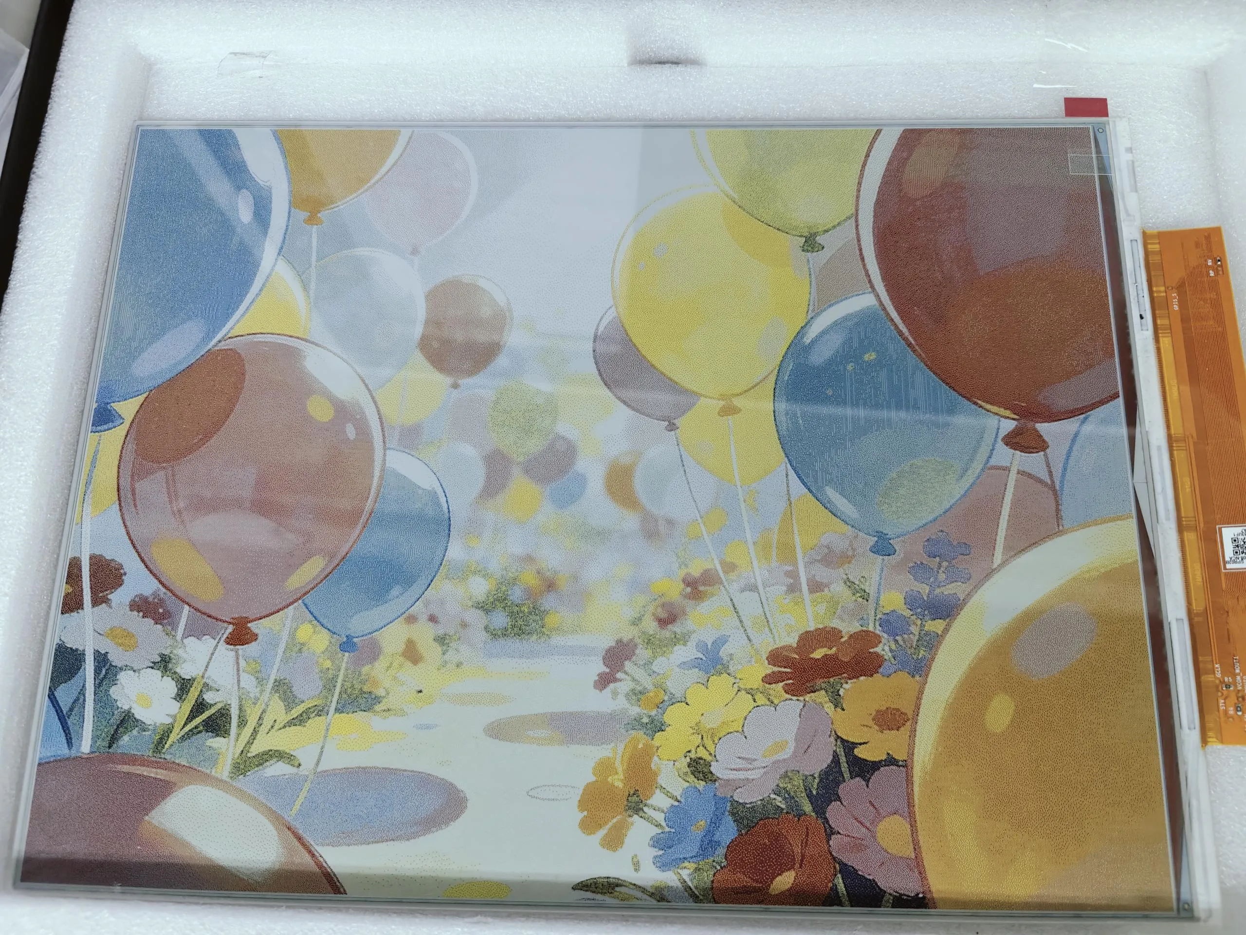
- This example reads BMP images from a TF card and refreshes them on the e-Paper display.
Hardware Connection
- Connect the board to the computer using a USB cable
- Insert the TF card module with a TF card containing a bmp folder with images in the root directory.
Code Analysis
_sdcard_init: TF card initializationGUI_ReadBmp_RGB_6Color("/sdcard/bmp/13in3E.bmp", 0, 0);: Image decoding
Operation Result
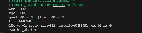
- Serial port prints TF card information.
- Reads and displays images from the TF card.
06_xiaozhi-esp32
Hardware Connection
- Connect the board to the computer using a USB cable
- Copy all files from the TF card folder to sdcard, then insert the TF card module
Example Description
- First download the example using your preferred method. After extracting, copy all files from the TF card directory to sdcard.
- The first boot will trigger a network configuration process. The voice will announce "Entering network configuration mode". At this point, use your phone to connect to
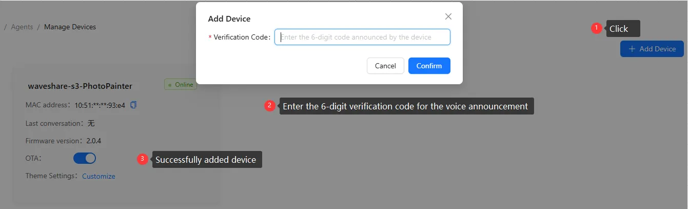
Xiaozhi-xxx(wherexxxis variable). - After successful network configuration, go to the Xiaozhi Console and add the corresponding device.
- Three working modes: Basic Mode (Mode 1), Local Server Mode (Mode 2), and AI Conversation Mode (Mode 3).
Mode 1
- The default mode is AI Conversation Mode (Mode 3). Press and hold the BOOT button to enter mode selection (the voice will announce it). Then press the BOOT button once to select Basic Mode (Mode 1). Press and hold the BOOT button again to enter this mode.
- Add photos you want to display to the
imgdirectory on the TF card. Only 24-bit BMP images with resolutions of 1600x1200 or 1200x1600 are accepted. - Press the BOOT button once to display an image from the
imgdirectory. - Press the BOOT button to cycle through images.
Mode 2
- Press and hold the BOOT button to enter mode selection; press the BOOT button twice, then press and hold the BOOT button again to enter this mode.
- Use your phone or computer to connect to the Wi-Fi
esp_networkwith password1234567890. After successful connection, go to the image selection interface as shown: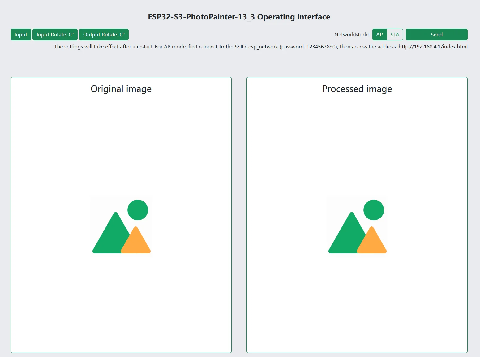
- On the web page, you can directly select, preview, and push images to the e-paper display.
- For AP mode: first connect your phone or computer to the Wi-Fi with SSID
esp_network(password:1234567890), then visithttp://192.168.4.1/index.html. - For STA mode: first configure the network using Mode 3, then visit
http://esp32-s3-photopainter-13_3.local/index.html.
Mode 3
- Press and hold the BOOT button to enter mode selection; press the BOOT button three times, then press and hold the BOOT button again to enter this mode.
- After initialization is complete, wake up the device with the wake word "Hello, Xiaozhi".
- After waking up, you can converse normally.
- Through conversation, you can retrieve and display the number of images in the
imgdirectory on the TF card. - Regarding AI-generated images: for example, you can say "Help me generate an image of the moon". To use this feature, you need to configure Volcanic Engine. Refer to Volcanic Engine Text-to-Image Configuration for details.
Volcanic Engine Text-to-Image Configuration
- Firstly, you need to obtain the access key, model name, and URL. Currently, a test model is being used, which will be discontinued later. Users need to configure their own models. The relevant code section and configuration in the
config.txtfile are shown below: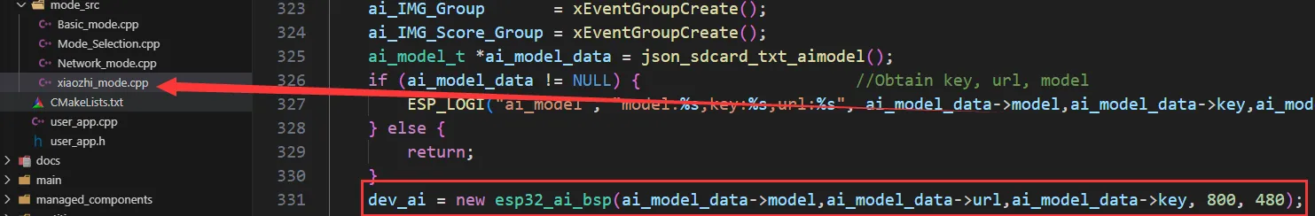

- Go to the Volcanic Engine Console
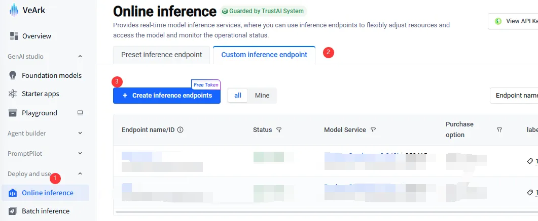
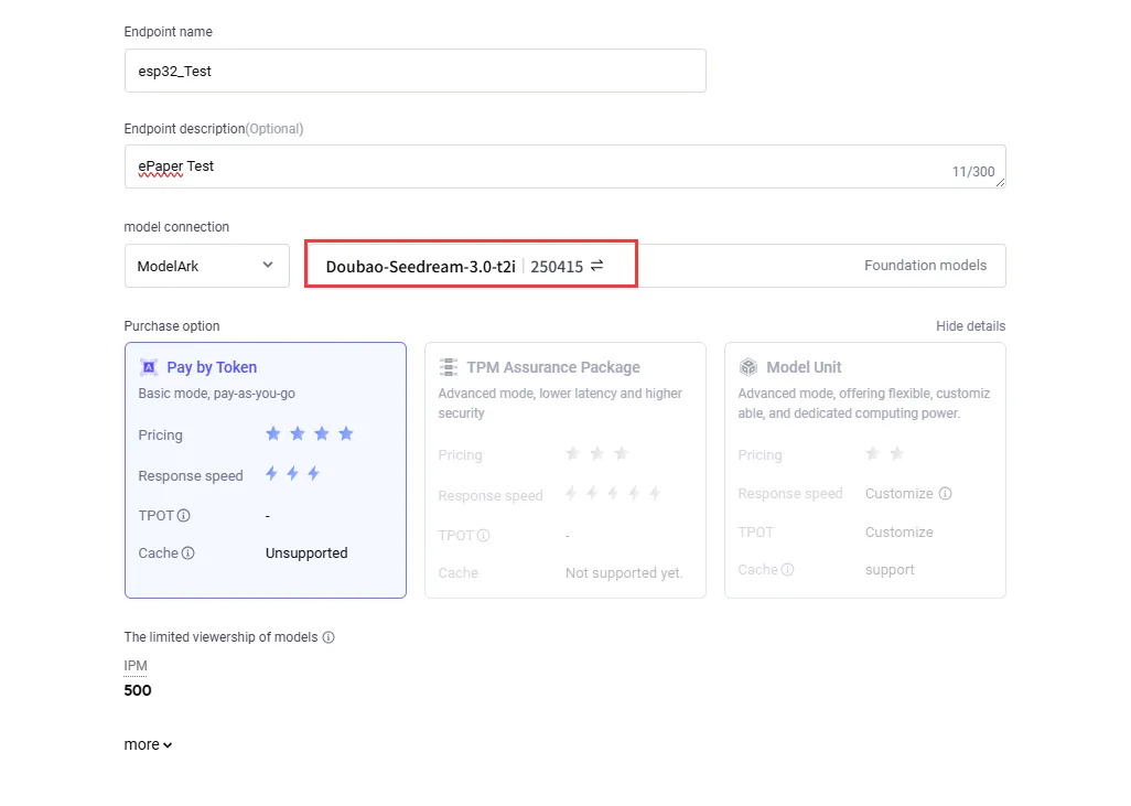
- Create the corresponding model. Be careful not to select the wrong model, as shown:
- Copy the corresponding key, model, and URL as shown:
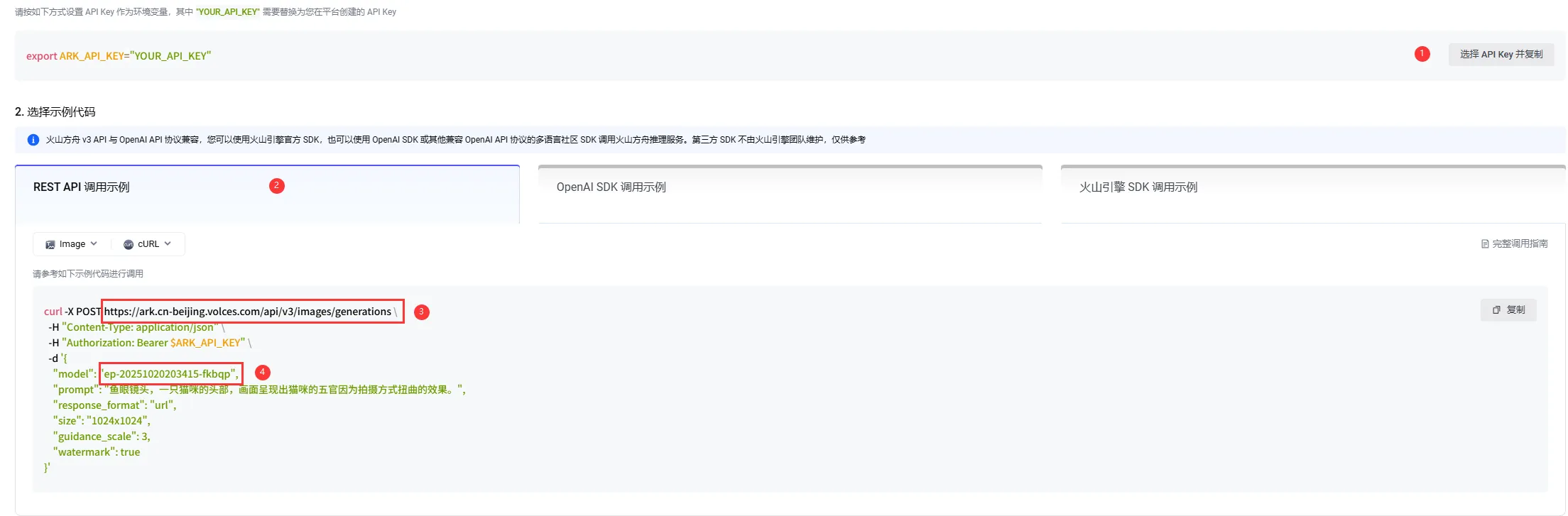
- Paste the copied
url,model, andkeyinto the corresponding key-value fields in theconfig.txtfile located in thesdcard->imgdirectory (see step 1, second image). New users can claim free Tokens.