Working with Arduino
This chapter contains the following sections. Please read as needed:
Arduino Getting Started
New to Arduino ESP32 development and looking for a quick start? We have prepared a comprehensive Getting Started Tutorial for you.
- Section 0: Getting to Know ESP32
- Section 1: Installing and Configuring Arduino IDE
- Section 2: Arduino Basics
- Section 3: Digital Output/Input
- Section 4: Analog Input
- Section 5: Pulse Width Modulation (PWM)
- Section 6: Serial Communication (UART)
- Section 7: I2C Communication
- Section 8: SPI Communication
- Section 9: Wi-Fi Basics
- Section 10: Web Server
- Section 11: Bluetooth
- Section 12: LVGL GUI Development
- Section 13: Comprehensive Project
Note: This tutorial uses the ESP32-S3-Zero as a reference example, and all hardware code is based on its pinout. Before you start, we recommend checking the pinout of your development board to ensure the pin configuration is correct.
Setting Up the Development Environment
1. Installing and Configuring the Arduino IDE
Please refer to the tutorial Installing and Configuring Arduino IDE to download and install the Arduino IDE and add ESP32 support.
2. Installing Libraries
You can click this link to download the example package for the ESP32-Touch-LCD-3.5 board from the Arduino directory. The Arduino\libraries directory within this package contains all the necessary library files required for this tutorial.
| Library/File Name | Description | Version | Installation Method |
|---|---|---|---|
| ESP32-audioI2S-master | Audio processing library | v3.4.0 | Via Library Manager or manual |
| GFX_Library_for_Arduino | GFX graphics library | v1.6.0 | Via Library Manager or manual |
| lvgl | LVGL graphics library | v8.4.0 | Via Library Manager or manual |
| OneButton | Button library | v2.6.1 | Via Library Manager or manual |
| SensorLib | Sensor driver library | v0.3.1 | Via Library Manager or manual |
| TCA9554 | I/O expander library | v0.1.2 | Via Library Manager or manual |
| XPowersLib | Power management library | v0.2.9 | Via Library Manager or manual |
| ESP32-A2DP | Bluetooth audio processing | — | Manual |
There are strong dependencies between versions of LVGL and its driver libraries. For example, a driver written for LVGL v8 may not be compatible with LVGL v9. To ensure that the examples can be reproduced reliably, it is recommended to use the specific versions listed in the table above. Mixing different versions of libraries may lead to compilation failures or runtime errors.
Installation Steps:
-
Download the example package.
-
Copy all folders (GFX_Library_for_Arduino, ESP32-audioI2S-master, etc.) in the
Arduino\librariesdirectory to the Arduino libraries folder.infoThe path to the Arduino libraries folder is typically:
c:\Users\<username>\Documents\Arduino\libraries.You can also locate it in the Arduino IDE by going to File > Preferences and checking the "Sketchbook location". The libraries folder is the
librariessubfolder within this path. -
For other installation methods, please refer to: Arduino Library Management Tutorial.
3. Additional Tips
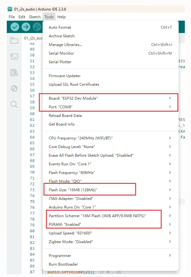
For ESP32-Touch-LCD-3.5 Arduino project parameter setting, you need to select the ESP32 Dev Module.
Example
The Arduino examples are located in the Arduino/examples directory of the example package.
| Example | Basic Description | Dependency Library |
|---|---|---|
| 01_i2s_audio | Read audio files from the TF card and play them | ESP32-audioI2S-master |
| 02_axp2101_example | Print data from the power management IC | XPowersLib |
| 03_button_example | Button test | OneButton |
| 04_es8311_example | Record audio for a period and play it back | es8311 |
| 05_pcf85063_example | Print data from the RTC | SensorLib |
| 06_tca9554_example | I/O expander test | TCA9554 |
| 07_sd_card_test | Test TF card read/write | - |
| 08_gfx_helloworld | Display "HelloWorld" on the screen | GFX_Library_for_Arduino, TCA9554 |
| 09_lvgl_arduino_v8 | lvgl v8.4.0 example program | GFX_Library_for_Arduino, TCA9554, lvgl, SensorLib |
| 10_lvgl_arduino_v9 | lvgl v9.3.0 example program | GFX_Library_for_Arduino, TCA9554, lvgl, SensorLib |
| 11_bt_music_receiver_arduino_i2s | Bluetooth music playback example | ESP32-A2DP, GFX_Library_for_Arduino, TCA9554, OneButton |
01_i2s_audio
This example demonstrates the ESP32-Touch-LCD-3.5 reading audio files from the TF card and playing them through the speaker, supporting MP3, AAC, WAV, and other formats.
Preparation
- Insert the TF card into the computer
- Create a folder named music in the root directory of the TF card
- Copy the 1.mp3 file from the data folder of this project to the music folder on the TF card
- Insert the TF card into ESP32-Touch-LCD-3.5
Operation Result
The device will play auido directly without showing content on the screen
Code
01_i2s_audio.ino
#include "Arduino.h"
#include "Audio.h"
#include "SPI.h"
#include "SD.h"
#include "FS.h"

#include "es8311.h"
#include "esp_check.h"
#include "TCA9554.h"
#include "Wire.h"

// Digital I/O used
#define SD_CS 15
#define SPI_MOSI 23
#define SPI_MISO 19
#define SPI_SCK 18

#define I2S_DOUT 12
#define I2S_BCLK 2
#define I2S_LRC 4

#define I2C_SDA 21
#define I2C_SCL 22

#define EXAMPLE_SAMPLE_RATE (16000)
#define EXAMPLE_MCLK_MULTIPLE (256)  // If not using 24-bit data width, 256 should be enough
#define EXAMPLE_MCLK_FREQ_HZ (EXAMPLE_SAMPLE_RATE * EXAMPLE_MCLK_MULTIPLE)
#define EXAMPLE_VOICE_VOLUME (75)

TCA9554 TCA(0x20);
Audio audio;


static esp_err_t es8311_codec_init(void) {

  es8311_handle_t es_handle = es8311_create(I2C_NUM_0, ES8311_ADDRRES_0);
  ESP_RETURN_ON_FALSE(es_handle, ESP_FAIL, TAG, "es8311 create failed");
  const es8311_clock_config_t es_clk = {
    .mclk_inverted = false,
    .sclk_inverted = false,
    .mclk_from_mclk_pin = false,
    // .mclk_frequency = EXAMPLE_MCLK_FREQ_HZ,
    .sample_frequency = EXAMPLE_SAMPLE_RATE
  };

  ESP_ERROR_CHECK(es8311_init(es_handle, &es_clk, ES8311_RESOLUTION_32, ES8311_RESOLUTION_32));
  // ESP_RETURN_ON_ERROR(es8311_sample_frequency_config(es_handle, EXAMPLE_SAMPLE_RATE * EXAMPLE_MCLK_MULTIPLE, EXAMPLE_SAMPLE_RATE), TAG, "set es8311 sample frequency failed");
  ESP_RETURN_ON_ERROR(es8311_voice_volume_set(es_handle, EXAMPLE_VOICE_VOLUME, NULL), TAG, "set es8311 volume failed");
  ESP_RETURN_ON_ERROR(es8311_microphone_config(es_handle, false), TAG, "set es8311 microphone failed");

  return ESP_OK;
}


void setup() {
  Serial.begin(115200);
  Wire.begin(I2C_SDA, I2C_SCL);
  TCA.begin();
  TCA.pinMode1(2,OUTPUT);
  TCA.write1(2, 1);

  es8311_codec_init();

  SPI.begin(SPI_SCK, SPI_MISO, SPI_MOSI, SD_CS);
  if (!SD.begin(SD_CS)) {
    esp_rom_printf("Card Mount Failed\n");
    while (1) {
    };
  }

  audio.setPinout(I2S_BCLK, I2S_LRC, I2S_DOUT);
  audio.setVolume(21);  // 0...21

  audio.connecttoFS(SD, "music/1.mp3");
}

void loop() {
  vTaskDelay(1);
  audio.loop();
  if (Serial.available()) {  // put streamURL in serial monitor
    audio.stopSong();
    String r = Serial.readString();
    r.trim();
    if (r.length() > 5) audio.connecttohost(r.c_str());
    log_i("free heap=%i", ESP.getFreeHeap());
  }
}

// optional
void audio_info(const char *info) {
  Serial.print("info        ");
  Serial.println(info);
}
void audio_id3data(const char *info) {  //id3 metadata
  Serial.print("id3data     ");
  Serial.println(info);
}
void audio_eof_mp3(const char *info) {  //end of file
  Serial.print("eof_mp3     ");
  Serial.println(info);
}
void audio_showstation(const char *info) {
  Serial.print("station     ");
  Serial.println(info);
}
void audio_showstreamtitle(const char *info) {
  Serial.print("streamtitle ");
  Serial.println(info);
}
void audio_bitrate(const char *info) {
  Serial.print("bitrate     ");
  Serial.println(info);
}
void audio_commercial(const char *info) {  //duration in sec
  Serial.print("commercial  ");
  Serial.println(info);
}
void audio_icyurl(const char *info) {  //homepage
  Serial.print("icyurl      ");
  Serial.println(info);
}
void audio_lasthost(const char *info) {  //stream URL played
  Serial.print("lasthost    ");
  Serial.println(info);
}
Code Analysis
-
Initialize the I2C peripheral, configure the ES8311 codec, and enable the PA_CTRL amplifier pin:
Wire.begin(I2C_SDA, I2C_SCL);TCA.begin();TCA.pinMode1(2,OUTPUT);TCA.write1(2, 1);es8311_codec_init(); -
Initialize the I2S peripheral, mount the TF card, set the playback volume, and play the MP3 file at path
music/1.mp3:SPI.begin(SPI_SCK, SPI_MISO, SPI_MOSI, SD_CS);if (!SD.begin(SD_CS)) {esp_rom_printf("Card Mount Failed\n");while (1) {};}audio.setPinout(I2S_BCLK, I2S_LRC, I2S_DOUT);audio.setVolume(21); // 0...21audio.connecttoFS(SD, "music/1.mp3");
02_axp2101_example
This example demonstrates using XPowers to drive the AXP2101 and prints data over the serial port.
Operation Result

Code
02_axp2101_example.ino
/*
! WARN:
Please do not run the example without knowing the external load voltage of the PMU,
it may burn your external load, please check the voltage setting before running the example,
if there is any loss, please bear it by yourself
*/
// #ifndef XPOWERS_NO_ERROR
// #error "Running this example is known to not damage the device! Please go and uncomment this!"
// #endif
// Defined using AXP2102
#define XPOWERS_CHIP_AXP2101

#include <Wire.h>
#include <Arduino.h>
#include "XPowersLib.h"

#ifndef CONFIG_PMU_SDA
#define CONFIG_PMU_SDA 21
#endif

#ifndef CONFIG_PMU_SCL
#define CONFIG_PMU_SCL 22
#endif

#ifndef CONFIG_PMU_IRQ
#define CONFIG_PMU_IRQ 35
#endif

bool  pmu_flag = 0;
XPowersPMU power;

const uint8_t i2c_sda = CONFIG_PMU_SDA;
const uint8_t i2c_scl = CONFIG_PMU_SCL;
const uint8_t pmu_irq_pin = CONFIG_PMU_IRQ;

void setFlag(void)
{
    pmu_flag = true;
}


void setup()
{
    Serial.begin(115200);

    bool result = power.begin(Wire, AXP2101_SLAVE_ADDRESS, i2c_sda, i2c_scl);

    if (result == false) {
        Serial.println("power is not online..."); while (1)delay(50);
    }

    Serial.printf("getID:0x%x\n", power.getChipID());

    // Set the minimum common working voltage of the PMU VBUS input,
    // below this value will turn off the PMU
    power.setVbusVoltageLimit(XPOWERS_AXP2101_VBUS_VOL_LIM_4V36);

    // Set the maximum current of the PMU VBUS input,
    // higher than this value will turn off the PMU
    power.setVbusCurrentLimit(XPOWERS_AXP2101_VBUS_CUR_LIM_1500MA);


    // Get the VSYS shutdown voltage
    uint16_t vol = power.getSysPowerDownVoltage();
    Serial.printf("->  getSysPowerDownVoltage:%u\n", vol);

    // Set VSY off voltage as 2600mV , Adjustment range 2600mV ~ 3300mV
    power.setSysPowerDownVoltage(2600);

    vol = power.getSysPowerDownVoltage();
    Serial.printf("->  getSysPowerDownVoltage:%u\n", vol);


    // DC1 IMAX=2A
    // 1500~3400mV,100mV/step,20steps
    power.setDC1Voltage(3300);
    Serial.printf("DC1  : %s   Voltage:%u mV \n",  power.isEnableDC1()  ? "+" : "-", power.getDC1Voltage());

    // DC2 IMAX=2A
    // 500~1200mV  10mV/step,71steps
    // 1220~1540mV 20mV/step,17steps
    power.setDC2Voltage(1000);
    Serial.printf("DC2  : %s   Voltage:%u mV \n",  power.isEnableDC2()  ? "+" : "-", power.getDC2Voltage());

    // DC3 IMAX=2A
    // 500~1200mV,10mV/step,71steps
    // 1220~1540mV,20mV/step,17steps
    // 1600~3400mV,100mV/step,19steps
    power.setDC3Voltage(3300);
    Serial.printf("DC3  : %s   Voltage:%u mV \n",  power.isEnableDC3()  ? "+" : "-", power.getDC3Voltage());

    // DCDC4 IMAX=1.5A
    // 500~1200mV,10mV/step,71steps
    // 1220~1840mV,20mV/step,32steps
    power.setDC4Voltage(1000);
    Serial.printf("DC4  : %s   Voltage:%u mV \n",  power.isEnableDC4()  ? "+" : "-", power.getDC4Voltage());

    // DC5 IMAX=2A
    // 1200mV
    // 1400~3700mV,100mV/step,24steps
    power.setDC5Voltage(3300);
    Serial.printf("DC5  : %s   Voltage:%u mV \n",  power.isEnableDC5()  ? "+" : "-", power.getDC5Voltage());

    // ALDO1 IMAX=300mA
    //500~3500mV, 100mV/step,31steps
    power.setALDO1Voltage(3300);

    // ALDO2 IMAX=300mA
    //500~3500mV, 100mV/step,31steps
    power.setALDO2Voltage(3300);

    // ALDO3 IMAX=300mA
    //500~3500mV, 100mV/step,31steps
    power.setALDO3Voltage(3300);

    // ALDO4 IMAX=300mA
    //500~3500mV, 100mV/step,31steps
    power.setALDO4Voltage(3300);

    // BLDO1 IMAX=300mA
    //500~3500mV, 100mV/step,31steps
    power.setBLDO1Voltage(3300);

    // BLDO2 IMAX=300mA
    //500~3500mV, 100mV/step,31steps
    power.setBLDO2Voltage(3300);

    //CPUSLDO IMAX=30mA
    // 500~1400mV,50mV/step,19steps
    power.setCPUSLDOVoltage(1000);

    // DLDO1 IMAX=300mA
    //500~3400mV, 100mV/step,29steps
    power.setDLDO1Voltage(3300);

    // DLDO2 IMAX=300mA
    //500~1400mV, 50mV/step,2steps
    power.setDLDO2Voltage(3300);


    // power.enableDC1();
    power.enableDC2();
    power.enableDC3();
    power.enableDC4();
    power.enableDC5();
    power.enableALDO1();
    power.enableALDO2();
    power.enableALDO3();
    power.enableALDO4();
    power.enableBLDO1();
    power.enableBLDO2();
    power.enableCPUSLDO();
    power.enableDLDO1();
    power.enableDLDO2();


    Serial.println("DCDC=======================================================================");
    Serial.printf("DC1  : %s   Voltage:%u mV \n",  power.isEnableDC1()  ? "+" : "-", power.getDC1Voltage());
    Serial.printf("DC2  : %s   Voltage:%u mV \n",  power.isEnableDC2()  ? "+" : "-", power.getDC2Voltage());
    Serial.printf("DC3  : %s   Voltage:%u mV \n",  power.isEnableDC3()  ? "+" : "-", power.getDC3Voltage());
    Serial.printf("DC4  : %s   Voltage:%u mV \n",  power.isEnableDC4()  ? "+" : "-", power.getDC4Voltage());
    Serial.printf("DC5  : %s   Voltage:%u mV \n",  power.isEnableDC5()  ? "+" : "-", power.getDC5Voltage());
    Serial.println("ALDO=======================================================================");
    Serial.printf("ALDO1: %s   Voltage:%u mV\n",  power.isEnableALDO1()  ? "+" : "-", power.getALDO1Voltage());
    Serial.printf("ALDO2: %s   Voltage:%u mV\n",  power.isEnableALDO2()  ? "+" : "-", power.getALDO2Voltage());
    Serial.printf("ALDO3: %s   Voltage:%u mV\n",  power.isEnableALDO3()  ? "+" : "-", power.getALDO3Voltage());
    Serial.printf("ALDO4: %s   Voltage:%u mV\n",  power.isEnableALDO4()  ? "+" : "-", power.getALDO4Voltage());
    Serial.println("BLDO=======================================================================");
    Serial.printf("BLDO1: %s   Voltage:%u mV\n",  power.isEnableBLDO1()  ? "+" : "-", power.getBLDO1Voltage());
    Serial.printf("BLDO2: %s   Voltage:%u mV\n",  power.isEnableBLDO2()  ? "+" : "-", power.getBLDO2Voltage());
    Serial.println("CPUSLDO====================================================================");
    Serial.printf("CPUSLDO: %s Voltage:%u mV\n",  power.isEnableCPUSLDO() ? "+" : "-", power.getCPUSLDOVoltage());
    Serial.println("DLDO=======================================================================");
    Serial.printf("DLDO1: %s   Voltage:%u mV\n",  power.isEnableDLDO1()  ? "+" : "-", power.getDLDO1Voltage());
    Serial.printf("DLDO2: %s   Voltage:%u mV\n",  power.isEnableDLDO2()  ? "+" : "-", power.getDLDO2Voltage());
    Serial.println("===========================================================================");

    // Set the time of pressing the button to turn off
    power.setPowerKeyPressOffTime(XPOWERS_POWEROFF_4S);
    uint8_t opt = power.getPowerKeyPressOffTime();
    Serial.print("PowerKeyPressOffTime:");
    switch (opt) {
    case XPOWERS_POWEROFF_4S: Serial.println("4 Second");
        break;
    case XPOWERS_POWEROFF_6S: Serial.println("6 Second");
        break;
    case XPOWERS_POWEROFF_8S: Serial.println("8 Second");
        break;
    case XPOWERS_POWEROFF_10S: Serial.println("10 Second");
        break;
    default:
        break;
    }
    // Set the button power-on press time
    power.setPowerKeyPressOnTime(XPOWERS_POWERON_128MS);
    opt = power.getPowerKeyPressOnTime();
    Serial.print("PowerKeyPressOnTime:");
    switch (opt) {
    case XPOWERS_POWERON_128MS: Serial.println("128 Ms");
        break;
    case XPOWERS_POWERON_512MS: Serial.println("512 Ms");
        break;
    case XPOWERS_POWERON_1S: Serial.println("1 Second");
        break;
    case XPOWERS_POWERON_2S: Serial.println("2 Second");
        break;
    default:
        break;
    }

    Serial.println("===========================================================================");

    bool en;

    // DCDC 120%(130%) high voltage turn off PMIC function
    en = power.getDCHighVoltagePowerDownEn();
    Serial.print("getDCHighVoltagePowerDownEn:");
    Serial.println(en ? "ENABLE" : "DISABLE");
    // DCDC1 85% low voltage turn off PMIC function
    en = power.getDC1LowVoltagePowerDownEn();
    Serial.print("getDC1LowVoltagePowerDownEn:");
    Serial.println(en ? "ENABLE" : "DISABLE");
    // DCDC2 85% low voltage turn off PMIC function
    en = power.getDC2LowVoltagePowerDownEn();
    Serial.print("getDC2LowVoltagePowerDownEn:");
    Serial.println(en ? "ENABLE" : "DISABLE");
    // DCDC3 85% low voltage turn off PMIC function
    en = power.getDC3LowVoltagePowerDownEn();
    Serial.print("getDC3LowVoltagePowerDownEn:");
    Serial.println(en ? "ENABLE" : "DISABLE");
    // DCDC4 85% low voltage turn off PMIC function
    en = power.getDC4LowVoltagePowerDownEn();
    Serial.print("getDC4LowVoltagePowerDownEn:");
    Serial.println(en ? "ENABLE" : "DISABLE");
    // DCDC5 85% low voltage turn off PMIC function
    en = power.getDC5LowVoltagePowerDownEn();
    Serial.print("getDC5LowVoltagePowerDownEn:");
    Serial.println(en ? "ENABLE" : "DISABLE");

    // power.setDCHighVoltagePowerDown(true);
    // power.setDC1LowVoltagePowerDown(true);
    // power.setDC2LowVoltagePowerDown(true);
    // power.setDC3LowVoltagePowerDown(true);
    // power.setDC4LowVoltagePowerDown(true);
    // power.setDC5LowVoltagePowerDown(true);

    // It is necessary to disable the detection function of the TS pin on the board
    // without the battery temperature detection function, otherwise it will cause abnormal charging
    power.disableTSPinMeasure();

    // power.enableTemperatureMeasure();

    // Enable internal ADC detection
    power.enableBattDetection();
    power.enableVbusVoltageMeasure();
    power.enableBattVoltageMeasure();
    power.enableSystemVoltageMeasure();


    /*
      The default setting is CHGLED is automatically controlled by the PMU.
    - XPOWERS_CHG_LED_OFF,
    - XPOWERS_CHG_LED_BLINK_1HZ,
    - XPOWERS_CHG_LED_BLINK_4HZ,
    - XPOWERS_CHG_LED_ON,
    - XPOWERS_CHG_LED_CTRL_CHG,
    * */
    power.setChargingLedMode(XPOWERS_CHG_LED_CTRL_CHG);


    // Force add pull-up
    pinMode(pmu_irq_pin, INPUT_PULLUP);
    attachInterrupt(pmu_irq_pin, setFlag, FALLING);


    // Disable all interrupts
    power.disableIRQ(XPOWERS_AXP2101_ALL_IRQ);
    // Clear all interrupt flags
    power.clearIrqStatus();
    // Enable the required interrupt function
    power.enableIRQ(
        XPOWERS_AXP2101_BAT_INSERT_IRQ    | XPOWERS_AXP2101_BAT_REMOVE_IRQ      |   //BATTERY
        XPOWERS_AXP2101_VBUS_INSERT_IRQ   | XPOWERS_AXP2101_VBUS_REMOVE_IRQ     |   //VBUS
        XPOWERS_AXP2101_PKEY_SHORT_IRQ    | XPOWERS_AXP2101_PKEY_LONG_IRQ       |   //POWER KEY
        XPOWERS_AXP2101_BAT_CHG_DONE_IRQ  | XPOWERS_AXP2101_BAT_CHG_START_IRQ       //CHARGE
        // XPOWERS_AXP2101_PKEY_NEGATIVE_IRQ | XPOWERS_AXP2101_PKEY_POSITIVE_IRQ   |   //POWER KEY
    );

    // Set the precharge charging current
    power.setPrechargeCurr(XPOWERS_AXP2101_PRECHARGE_50MA);
    // Set constant current charge current limit
    power.setChargerConstantCurr(XPOWERS_AXP2101_CHG_CUR_200MA);
    // Set stop charging termination current
    power.setChargerTerminationCurr(XPOWERS_AXP2101_CHG_ITERM_25MA);

    // Set charge cut-off voltage
    power.setChargeTargetVoltage(XPOWERS_AXP2101_CHG_VOL_4V1);

    // Set the watchdog trigger event type
    power.setWatchdogConfig(XPOWERS_AXP2101_WDT_IRQ_TO_PIN);
    // Set watchdog timeout
    power.setWatchdogTimeout(XPOWERS_AXP2101_WDT_TIMEOUT_4S);
    // Enable watchdog to trigger interrupt event
    power.enableWatchdog();

    // power.disableWatchdog();

    // Enable Button Battery charge
    power.enableButtonBatteryCharge();

    // Set Button Battery charge voltage
    power.setButtonBatteryChargeVoltage(3300);

}

void printPMU()
{
    Serial.print("isCharging:"); Serial.println(power.isCharging() ? "YES" : "NO");
    Serial.print("isDischarge:"); Serial.println(power.isDischarge() ? "YES" : "NO");
    Serial.print("isStandby:"); Serial.println(power.isStandby() ? "YES" : "NO");
    Serial.print("isVbusIn:"); Serial.println(power.isVbusIn() ? "YES" : "NO");
    Serial.print("isVbusGood:"); Serial.println(power.isVbusGood() ? "YES" : "NO");
    Serial.print("getChargerStatus:");
    uint8_t charge_status = power.getChargerStatus();
    if (charge_status == XPOWERS_AXP2101_CHG_TRI_STATE) {
        Serial.println("tri_charge");
    } else if (charge_status == XPOWERS_AXP2101_CHG_PRE_STATE) {
        Serial.println("pre_charge");
    } else if (charge_status == XPOWERS_AXP2101_CHG_CC_STATE) {
        Serial.println("constant charge");
    } else if (charge_status == XPOWERS_AXP2101_CHG_CV_STATE) {
        Serial.println("constant voltage");
    } else if (charge_status == XPOWERS_AXP2101_CHG_DONE_STATE) {
        Serial.println("charge done");
    } else if (charge_status == XPOWERS_AXP2101_CHG_STOP_STATE) {
        Serial.println("not charge");
    }

    Serial.print("getBattVoltage:"); Serial.print(power.getBattVoltage()); Serial.println("mV");
    Serial.print("getVbusVoltage:"); Serial.print(power.getVbusVoltage()); Serial.println("mV");
    Serial.print("getSystemVoltage:"); Serial.print(power.getSystemVoltage()); Serial.println("mV");

    // The battery percentage may be inaccurate at first use, the PMU will automatically
    // learn the battery curve and will automatically calibrate the battery percentage
    // after a charge and discharge cycle
    if (power.isBatteryConnect()) {
        Serial.print("getBatteryPercent:"); Serial.print(power.getBatteryPercent()); Serial.println("%");
    }

    Serial.println();
}


void enterPmuSleep(void)
{
    // Set the wake-up source to PWRKEY
    power.wakeupControl(XPOWERS_AXP2101_WAKEUP_IRQ_PIN_TO_LOW, true);

    // Set sleep flag
    power.enableSleep();

    power.disableDC2();
    power.disableDC3();
    power.disableDC4();
    power.disableDC5();

    power.disableALDO1();
    power.disableALDO2();
    power.disableALDO3();
    power.disableALDO4();

    power.disableBLDO1();
    power.disableBLDO2();

    power.disableCPUSLDO();
    power.disableDLDO1();
    power.disableDLDO2();

    // Finally, turn off the power of the control chip
    power.disableDC1();
}

void loop()
{

    if (pmu_flag) {

        pmu_flag = false;

        // Get PMU Interrupt Status Register
        uint32_t status = power.getIrqStatus();
        Serial.print("STATUS => HEX:");
        Serial.print(status, HEX);
        Serial.print(" BIN:");
        Serial.println(status, BIN);

        if (power.isDropWarningLevel2Irq()) {
            Serial.println("isDropWarningLevel2");
        }
        if (power.isDropWarningLevel1Irq()) {
            Serial.println("isDropWarningLevel1");
        }
        if (power.isGaugeWdtTimeoutIrq()) {
            Serial.println("isWdtTimeout");
        }
        if (power.isBatChargerOverTemperatureIrq()) {
            Serial.println("isBatChargeOverTemperature");
        }
        if (power.isBatWorkOverTemperatureIrq()) {
            Serial.println("isBatWorkOverTemperature");
        }
        if (power.isBatWorkUnderTemperatureIrq()) {
            Serial.println("isBatWorkUnderTemperature");
        }
        if (power.isVbusInsertIrq()) {
            Serial.println("isVbusInsert");
        }
        if (power.isVbusRemoveIrq()) {
            Serial.println("isVbusRemove");
        }
        if (power.isBatInsertIrq()) {
            Serial.println("isBatInsert");
        }
        if (power.isBatRemoveIrq()) {
            Serial.println("isBatRemove");
        }

        if (power.isPekeyShortPressIrq()) {
            Serial.println("isPekeyShortPress");
            // enterPmuSleep();

            Serial.print("Read pmu data buffer .");
            uint8_t data[4] = {0};
            power.readDataBuffer(data, XPOWERS_AXP2101_DATA_BUFFER_SIZE);
            for (int i = 0; i < 4; ++i) {
                Serial.print(data[i]);
                Serial.print(",");
            }
            Serial.println();
        }

        if (power.isPekeyLongPressIrq()) {
            Serial.println("isPekeyLongPress");
            Serial.println("write pmu data buffer .");
            uint8_t data[4] = {1, 2, 3, 4};
            power.writeDataBuffer(data, XPOWERS_AXP2101_DATA_BUFFER_SIZE);
        }

        if (power.isPekeyNegativeIrq()) {
            Serial.println("isPekeyNegative");
        }
        if (power.isPekeyPositiveIrq()) {
            Serial.println("isPekeyPositive");
        }
        if (power.isWdtExpireIrq()) {
            Serial.println("isWdtExpire");
            printPMU();
        }
        if (power.isLdoOverCurrentIrq()) {
            Serial.println("isLdoOverCurrentIrq");
        }
        if (power.isBatfetOverCurrentIrq()) {
            Serial.println("isBatfetOverCurrentIrq");
        }
        if (power.isBatChargeDoneIrq()) {
            Serial.println("isBatChargeDone");
        }
        if (power.isBatChargeStartIrq()) {
            Serial.println("isBatChargeStart");
        }
        if (power.isBatDieOverTemperatureIrq()) {
            Serial.println("isBatDieOverTemperature");
        }
        if (power.isChargeOverTimeoutIrq()) {
            Serial.println("isChargeOverTimeout");
        }
        if (power.isBatOverVoltageIrq()) {
            Serial.println("isBatOverVoltage");
        }

        // Clear PMU Interrupt Status Register
        power.clearIrqStatus();

    }
    delay(10);
}
Code Analysis
-
Initialize the I2C peripheral and the AXP2101 battery management IC:
bool result = power.begin(Wire, AXP2101_SLAVE_ADDRESS, i2c_sda, i2c_scl);if (result == false) {Serial.println("power is not online...");while (1) delay(50);}
03_button_example
This example demonstrates using the OneButton library to read the single-click, double-click, and long-press states of the BOOT, PWR, and PLUS buttons, and prints them over the serial port.
Operation Result

Code
03_button_example.ino
#include "OneButton.h"

#define PIN_INPUT1 0
#define PIN_INPUT2 36


// Setup a new OneButton on pin PIN_INPUT2.
OneButton button1(PIN_INPUT1, true);
// Setup a new OneButton on pin PIN_INPUT2.
OneButton button2(PIN_INPUT2, false);


// setup code here, to run once:
void setup() {
  // Setup the Serial port. see https://docs.arduino.cc/language-reference/en/functions/communication/serial/ifSerial/
  Serial.begin(115200);
  while (!Serial){
    ;  // wait for serial port to connect. Needed for Leonardo only
  }
  Serial.println("Starting TwoButtons...");

  // link the button 1 functions.
  button1.attachClick(click1);
  button1.attachDoubleClick(doubleclick1);
  button1.attachLongPressStart(longPressStart1);
  button1.attachLongPressStop(longPressStop1);
  button1.attachDuringLongPress(longPress1);

  // link the button 2 functions.
  button2.attachClick(click2);
  button2.attachDoubleClick(doubleclick2);
  button2.attachLongPressStart(longPressStart2);
  button2.attachLongPressStop(longPressStop2);
  button2.attachDuringLongPress(longPress2);

}  // setup


// main code here, to run repeatedly:
void loop() {
  // keep watching the push buttons:
  button1.tick();
  button2.tick();

  // You can implement other code in here or just wait a while
  delay(10);
}  // loop


// ----- button 1 callback functions

// This function will be called when the button1 was pressed 1 time (and no 2. button press followed).
void click1() {
  Serial.println("BOOT Button click.");
}  // click1


// This function will be called when the button1 was pressed 2 times in a short timeframe.
void doubleclick1() {
  Serial.println("BOOT Button doubleclick.");
}  // doubleclick1


// This function will be called once, when the button1 is pressed for a long time.
void longPressStart1() {
  Serial.println("BOOT Button longPress start");
}  // longPressStart1


// This function will be called often, while the button1 is pressed for a long time.
void longPress1() {
  Serial.println("BOOT Button longPress...");
}  // longPress1


// This function will be called once, when the button1 is released after beeing pressed for a long time.
void longPressStop1() {
  Serial.println("BOOT Button longPress stop");
}  // longPressStop1


// ... and the same for button 2:

void click2() {
  Serial.println("PWR Button click.");
}  // click2


void doubleclick2() {
  Serial.println("PWR Button doubleclick.");
}  // doubleclick2


void longPressStart2() {
  Serial.println("PWR Button longPress start");
}  // longPressStart2


void longPress2() {
  Serial.println("PWR Button longPress...");
}  // longPress2

void longPressStop2() {
  Serial.println("PWR Button longPress stop");
}  // longPressStop2


// End
Code Analysis
-
Bind button event callback functions:
button1.attachClick(click1);button1.attachDoubleClick(doubleclick1);button1.attachLongPressStart(longPressStart1);button1.attachLongPressStop(longPressStop1);button1.attachDuringLongPress(longPress1);
04_es8311_example
This example demonstrates driving the ES8311 audio codec with the ESP32-Touch-LCD-3.5 to implement audio recording and playback.
Operation Result
- No visual feedback on the screen.
- Press the RST button on the ESP32-Touch-LCD-3.5 to start recording; playback begins 5 seconds later.
Code
04_es8311_example.ino
#include <Arduino.h>
#include "ESP_I2S.h"

#include "esp_check.h"

#include "Wire.h"
#include "es8311.h"
#include "TCA9554.h"

#define I2C_SDA 21
#define I2C_SCL 22

#define I2S_NUM I2S_NUM_0

#define I2S_MCK_PIN -1
#define I2S_BCK_PIN 2
#define I2S_LRCK_PIN 4
#define I2S_DOUT_PIN 12
#define I2S_DIN_PIN 34

#define EXAMPLE_SAMPLE_RATE (48000)
#define EXAMPLE_MCLK_MULTIPLE (256)  // If not using 24-bit data width, 256 should be enough
#define EXAMPLE_MCLK_FREQ_HZ (EXAMPLE_SAMPLE_RATE * EXAMPLE_MCLK_MULTIPLE)
#define EXAMPLE_VOICE_VOLUME (70)

I2SClass i2s;
TCA9554 TCA(0x20);

void setupI2S() {
  i2s.setPins(I2S_BCK_PIN, I2S_LRCK_PIN, I2S_DOUT_PIN, I2S_DIN_PIN, I2S_MCK_PIN);
  // Initialize the I2S bus in standard mode
  if (!i2s.begin(I2S_MODE_STD, EXAMPLE_SAMPLE_RATE, I2S_DATA_BIT_WIDTH_16BIT, I2S_SLOT_MODE_STEREO, I2S_STD_SLOT_BOTH)) {
    Serial.println("Failed to initialize I2S bus!");
    return;
  }
}


static esp_err_t es8311_codec_init(void) {
  es8311_handle_t es_handle = es8311_create(I2C_NUM_0, ES8311_ADDRRES_0);
  ESP_RETURN_ON_FALSE(es_handle, ESP_FAIL, TAG, "es8311 create failed");
  const es8311_clock_config_t es_clk = {
    .mclk_inverted = false,
    .sclk_inverted = false,
    .mclk_from_mclk_pin = false,
    // .mclk_frequency = EXAMPLE_MCLK_FREQ_HZ,
    .sample_frequency = EXAMPLE_SAMPLE_RATE
  };

  ESP_ERROR_CHECK(es8311_init(es_handle, &es_clk, ES8311_RESOLUTION_32, ES8311_RESOLUTION_32));
  ESP_RETURN_ON_ERROR(es8311_voice_volume_set(es_handle, EXAMPLE_VOICE_VOLUME, NULL), TAG, "set es8311 volume failed");
  ESP_RETURN_ON_ERROR(es8311_microphone_config(es_handle, false), TAG, "set es8311 microphone failed");

  return ESP_OK;
}

void setup() {
  uint8_t *wav_buffer;
  size_t wav_size;
  Serial.begin(115200);
  Wire.begin(I2C_SDA, I2C_SCL);
  es8311_codec_init();
  TCA.begin();
  TCA.pinMode1(2,OUTPUT);
  TCA.write1(2, 1);

  setupI2S();
  Serial.println("I2S Initialized");

  wav_buffer = i2s.recordWAV(5, &wav_size);
  delay(1000);
  Serial.println("I2S playWAV");
  i2s.playWAV(wav_buffer, wav_size);
}

void loop() {
  delay(1000);
}
Code Analysis
-
Initialize I2C, ES8311 and I2S:
Wire.begin(I2C_SDA, I2C_SCL);es8311_codec_init();setupI2S(); -
Record audio for 5 seconds and play the recorded content:
wav_buffer = i2s.recordWAV(5, &wav_size);delay(1000);Serial.println("I2S playWAV");i2s.playWAV(wav_buffer, wav_size);
05_pcf85063_example
This example demonstrates driving the PCF85063 with the ESP32-Touch-LCD-3.5 to set and retrieve time and date.
Operation Result
- No visual feedback on the screen.
- Open the serial port monitor.
Code
05_pcf85063_example.ino
#include <Wire.h>
#include <SPI.h>
#include <Arduino.h>
#include <SensorPCF85063.hpp>
#ifndef SENSOR_SDA
#define SENSOR_SDA 21
#endif
#ifndef SENSOR_SCL
#define SENSOR_SCL 22
#endif
#ifndef SENSOR_IRQ
#define SENSOR_IRQ 39
#endif
SensorPCF85063 rtc;
uint32_t interval = 0;
uint32_t loopCount = 0;
void printInt(int val)
{
if (val < 10) {
Serial.print("0");
}
Serial.print(val);
}
void setup()
{
Serial.begin(115200);
// Wait for the serial port to be ready
while (!Serial);
// Try to initialize the RTC module using I2C with specified SDA and SCL pins
if (!rtc.begin(Wire, SENSOR_SDA, SENSOR_SCL)) {
Serial.println("Failed to find PCF85063 - check your wiring!");
// Enter an infinite loop to halt the program
while (1) {
delay(1000);
}
}
uint16_t year = 2025;
uint8_t month = 1;
uint8_t day = 1;
uint8_t hour = 12;
uint8_t minute = 00;
uint8_t second = 00;
// Set the defined date and time on the RTC
rtc.setDateTime(year, month, day, hour, minute, second);
if (!rtc.isClockIntegrityGuaranteed()) {
Serial.println("[ERROR]:Clock integrity is not guaranteed; oscillator has stopped or has been interrupted");
}
}
void loop()
{
// Check if one second has passed since the last update
if (millis() > interval) {
// Update the interval to the current time
interval = millis() + 1000;
// Retrieve the current date and time from the RTC
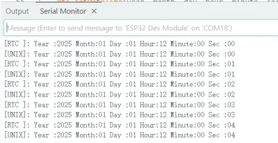
RTC_DateTime datetime = rtc.getDateTime();
Serial.print("[RTC ]:");
Serial.print(" Year :"); printInt(datetime.getYear());
Serial.print(" Month:"); printInt(datetime.getMonth());
Serial.print(" Day :"); printInt(datetime.getDay());
Serial.print(" Hour:"); printInt(datetime.getHour());
Serial.print(" Minute:"); printInt(datetime.getMinute());
Serial.print(" Sec :"); printInt(datetime.getSecond());
Serial.println();
// Convert the RTC date and time to Unix time
struct tm info = datetime.toUnixTime();
Serial.print("[UNIX]:");
Serial.print(" Year :"); printInt(info.tm_year + 1900); // tm_year starts counting from 1900
Serial.print(" Month:"); printInt(info.tm_mon + 1); // tm_mon range is 0 - 11, 0 means January
Serial.print(" Day :"); printInt(info.tm_mday);
Serial.print(" Hour:"); printInt(info.tm_hour);
Serial.print(" Minute:"); printInt(info.tm_min);
Serial.print(" Sec :"); printInt(info.tm_sec);
Serial.println();
// Set a new Unix time at the 10th loop iteration
if (loopCount == 10) {
Serial.print("Set Unix Time:");
Serial.println();
Serial.println();
struct tm utc_tm;
utc_tm.tm_year = 2025 - 1900; // tm_year starts counting from 1900
utc_tm.tm_mon = 0; // tm_mon range is 0 - 11, 0 means January
utc_tm.tm_mday = 23;
utc_tm.tm_hour = 7;
utc_tm.tm_min = 1;
utc_tm.tm_sec = 28;
rtc.setDateTime(utc_tm);
}
// Set a UTC time with a time zone offset of 8 hours at the 20th loop iteration
if (loopCount == 20) {
Serial.print("Set UTC time to time zone offset 8 hours:");
Serial.println();
Serial.println();
struct tm utc_tm;
utc_tm.tm_year = 2025 - 1900; // tm_year starts counting from 1900
utc_tm.tm_mon = 0; // tm_mon range is 0 - 11, 0 means January
utc_tm.tm_mday = 23;
utc_tm.tm_hour = 7;
utc_tm.tm_min = 1;
utc_tm.tm_sec = 28;
rtc.convertUtcToTimezone(utc_tm, 8 * 3600);
rtc.setDateTime(utc_tm);
}
if (loopCount > 30) {
char buf[64];
struct tm timeinfo;
// Get the time C library structure
rtc.getDateTime(&timeinfo);
// Format the output using the strftime function
// For more formats, please refer to :
// https://man7.org/linux/man-pages/man3/strftime.3.html
size_t written = strftime(buf, 64, "%A, %B %d %Y %H:%M:%S", &timeinfo);
if (written != 0) {
Serial.println(buf);
}
written = strftime(buf, 64, "%b %d %Y %H:%M:%S", &timeinfo);
if (written != 0) {
Serial.println(buf);
}
written = strftime(buf, 64, "%A, %d. %B %Y %I:%M%p", &timeinfo);
if (written != 0) {
Serial.println(buf);
}
}
++loopCount;
}
}
Code Analysis
-
Initialization:
// Try to initialize the RTC module using I2C with specified SDA and SCL pinsif (!rtc.begin(Wire, SENSOR_SDA, SENSOR_SCL)) {Serial.println("Failed to find PCF85063 - check your wiring!");// Enter an infinite loop to halt the programwhile (1) {delay(1000);}} -
Set the time and date:
rtc.setDateTime(year, month, day, hour, minute, second); -
Get the time and date:
RTC_DateTime datetime = rtc.getDateTime();
06_tca9554_example
This example demonstrates driving the TCA9554 with ESP32-Touch-LCD-3.5 to perform read and write operations on the pins of the extended IO.
Operation Result
- No visual feedback on the screen.
- Open the serial port monitor.

Code
06_tca9554_example.ino
#include "TCA9554.h"


TCA9554 TCA(0x20);


void setup()
{
  Serial.begin(115200);
  Serial.println(__FILE__);
  Serial.print("TCA9554_LIB_VERSION: ");
  Serial.println(TCA9554_LIB_VERSION);
  Serial.println();

  Wire.begin(21, 22);
  TCA.begin();


  Serial.println("Set pinMode8 OUTPUT");
  for (int pin = 0; pin < 8; pin++)
  {
    TCA.pinMode1(pin, OUTPUT);
  }

  for (int pin = 0; pin < 8; pin++)
  {
    TCA.write1(pin, LOW);
  }
  delay(1000);
  Serial.println("Set pinMode8 INPUT");
  for (int pin = 0; pin < 8; pin++)
  {
    TCA.pinMode1(pin, INPUT);
  }
}


void loop()
{
  Serial.print("INPUT->");
  for (int pin = 0; pin < 8; pin++)
  {
    int val = TCA.read1(pin);
    Serial.printf("pin%d: %d\t", pin, val);
  }
  Serial.println();
  Serial.println("\ndone...");
  delay(1000);
}
Code Analysis
-
Set pin mode:
TCA.pinMode1(pin, OUTPUT); -
Set pin level:
TCA.write1(pin, LOW); -
Read pin level:
int val = TCA.read1(pin);
07_sd_card_test
This example demonstrates testing TF card read/write functionality with the ESP32-Touch-LCD-3.5.
Hardware Connection
*Connect the board to the computer *Insert the TF card into the card slot (the TF card must be formatted as FAT32)
Operation Result
- No visual feedback on the screen.
- Open the serial port monitor.
Code
07_sd_card_test.ino
#include "FS.h"
#include "SD.h"
#include "SPI.h"
#define REASSIGN_PINS
int sck = 18;
int miso = 19;
int mosi = 23;
int cs = 15;
void listDir(fs::FS &fs, const char *dirname, uint8_t levels) {
Serial.printf("Listing directory: %s\n", dirname);
File root = fs.open(dirname);
if (!root) {
Serial.println("Failed to open directory");
return;
}
if (!root.isDirectory()) {
Serial.println("Not a directory");
return;
}
File file = root.openNextFile();
while (file) {
if (file.isDirectory()) {
Serial.print(" DIR : ");
Serial.println(file.name());
if (levels) {
listDir(fs, file.path(), levels - 1);
}
}else{
Serial.print(" FILE: ");
Serial.print(file.name());
Serial.print(" SIZE: ");
Serial.println(file.size());
}
file = root.openNextFile();
}
}
void createDir(fs::FS &fs, const char *path) {
Serial.printf("Creating Dir: %s\n", path);
if (fs.mkdir(path)) {
Serial.println("Dir created");
}else{
Serial.println("mkdir failed");
}
}
void removeDir(fs::FS &fs, const char *path) {
Serial.printf("Removing Dir: %s\n", path);
if (fs.rmdir(path)) {
Serial.println("Dir removed");
}else{
Serial.println("rmdir failed");
}
}
void readFile(fs::FS &fs, const char *path) {
Serial.printf("Reading file: %s\n", path);
File file = fs.open(path);
if (!file) {
Serial.println("Failed to open file for reading");
return;
}
Serial.print("Read from file: ");
while (file.available()) {
Serial.write(file.read());
}
file.close();
}
void writeFile(fs::FS &fs, const char *path, const char *message) {
Serial.printf("Writing file: %s\n", path);
File file = fs.open(path, FILE_WRITE);
if (!file) {
Serial.println("Failed to open file for writing");
return;
}
if (file.print(message)) {
Serial.println("File written");
}else{
Serial.println("Write failed");
}
file.close();
}
void appendFile(fs::FS &fs, const char *path, const char *message) {
Serial.printf("Appending to file: %s\n", path);
File file = fs.open(path, FILE_APPEND);
if (!file) {
Serial.println("Failed to open file for appending");
return;
}
if (file.print(message)) {
Serial.println("Message appended");
}else{
Serial.println("Append failed");
}
file.close();
}
void renameFile(fs::FS &fs, const char *path1, const char *path2) {
Serial.printf("Renaming file %s to %s\n", path1, path2);
if (fs.rename(path1, path2)) {
Serial.println("File renamed");
}else{
Serial.println("Rename failed");
}
}
deleteFile(fs::FS &fs, const char *path) {
Serial.printf("Deleting file: %s\n", path);
if (fs.remove(path)) {
Serial.println("File deleted");
}else{
Serial.println("Delete failed");
}
}
void testFileIO(fs::FS &fs, const char *path) {
File file = fs.open(path);
static uint8_t buf[512];
size_t len = 0;
uint32_t start = millis();
uint32_t end = start;
if (file) {
len = file.size();
size_t flen = len;
start = millis();
while (len) {
size_t toRead = len;
if (toRead > 512) {
toRead = 512;
}
file.read(buf, toRead);
len -= toRead;
}
end = millis() - start;
Serial.printf("%u bytes read for %lu ms\n", flen, end);
file.close();
}else{
Serial.println("Failed to open file for reading");
}
file = fs.open(path, FILE_WRITE);
if (!file) {
Serial.println("Failed to open file for writing");
return;
}
size_t i;
start = millis();
for (i = 0; i < 2048; i++) {
file.write(buf, 512);
}
end = millis() - start;
Serial.printf("%u bytes written for %lu ms\n", 2048 * 512, end);
file.close();
}
void setup() {
Serial.begin(115200);
#ifdef REASSIGN_PINS
SPI.begin(sck, miso, mosi, cs);
if (!SD.begin(cs)) {
#else
if (!SD.begin()) {
#endif
Serial.println("Card Mount Failed");
return;
}
uint8_t cardType = SD.cardType();
if (cardType == CARD_NONE) {
Serial.println("No TF card attached");
return;
}
Serial.print("TF Card Type: ");
if (cardType == CARD_MMC) {
Serial.println("MMC");
} else if (cardType == CARD_SD) {
Serial.println("SDSC");
} else if (cardType == CARD_SDHC) {
Serial.println("SDHC");
}else{
Serial.println("UNKNOWN");
}
uint64_t cardSize = SD.cardSize() / (1024 * 1024);
Serial.printf("TF Card Size: %lluMB\n", cardSize);
listDir(SD, "/", 0);
createDir(SD, "/mydir");
listDir(SD, "/", 0);
removeDir(SD, "/mydir");
listDir(SD, "/", 2);
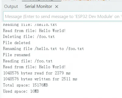
writeFile(SD, "/hello.txt", "Hello ");
appendFile(SD, "/hello.txt", "World!\n");
readFile(SD, "/hello.txt");
deleteFile(SD, "/foo.txt");
renameFile(SD, "/hello.txt", "/foo.txt");
readFile(SD, "/foo.txt");
testFileIO(SD, "/test.txt");
Serial.printf("Total space: %lluMB\n", SD.totalBytes() / (1024 * 1024));
Serial.printf("Used space: %lluMB\n", SD.usedBytes() / (1024 * 1024));
}
void loop() {}
Code Analysis
-
Initialization:
if(!SD_MMC.setPins(clk, cmd, d0)){Serial.println("Pin change failed!");return;}if (!SD_MMC.begin( "/sdcard", true)) {Serial.println("Card Mount Failed");return;}
08_gfx_helloworld
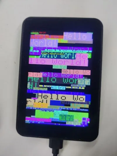
This example demonstrates using the GFX_Library_for_Arduino library to drive the screen on the ESP32-Touch-LCD-3.5 and display "HelloWorld".
Operation Result
Code
08_gfx_helloworld.ino
#include <Arduino_GFX_Library.h>
#include "TCA9554.h"


#define GFX_BL 25 // default backlight pin, you may replace DF_GFX_BL to actual backlight pin

TCA9554 TCA(0x20);

Arduino_DataBus *bus = new Arduino_ESP32SPI(27 /* DC */, 5 /* CS */, 18 /* SCK */, 23 /* MOSI */, 19 /* MISO */);

Arduino_GFX *gfx = new Arduino_ST7796(bus, GFX_NOT_DEFINED  /* RST */, 0 /* rotation */, true /* IPS */);


void setup(void)
{
#ifdef DEV_DEVICE_INIT
  DEV_DEVICE_INIT();
#endif
  Wire.begin(21, 22);
  TCA.begin();
  TCA.pinMode1(0,OUTPUT);
  TCA.write1(0, 1);
  delay(10);
  TCA.write1(0, 0);
  delay(10);
  TCA.write1(0, 1);
  delay(200);

  Serial.begin(115200);
  // Serial.setDebugOutput(true);
  // while(!Serial);
  Serial.println("Arduino_GFX Hello World example");

  // Init Display
  if (!gfx->begin())
  {
    Serial.println("gfx->begin() failed!");
  }
  gfx->fillScreen(RGB565_BLACK);

#ifdef GFX_BL
  pinMode(GFX_BL, OUTPUT);
  digitalWrite(GFX_BL, HIGH);
#endif

  gfx->setCursor(10, 10);
  gfx->setTextColor(RGB565_RED);
  gfx->println("Hello World!");

  delay(5000); // 5 seconds
}

void loop()
{
  gfx->setCursor(random(gfx->width()), random(gfx->height()));
  gfx->setTextColor(random(0xffff), random(0xffff));
  gfx->setTextSize(random(6) /* x scale */, random(6) /* y scale */, random(2) /* pixel_margin */);
  gfx->println("Hello World!");

  delay(1000); // 1 second
}
Code Analysis
-
Configure the screen interface and resolution, etc.:
Arduino_DataBus *bus = new Arduino_ESP32SPI(27 /* DC */, 5 /* CS */, 18 /* SCK */, 23 /* MOSI */, 19 /* MISO */);Arduino_GFX *gfx = new Arduino_ST7796(bus, GFX_NOT_DEFINED /* RST */, 0 /* rotation */, true /* IPS */);
09_lvgl_arduino_v8
This example demonstrates running an LVGL (v8.4.0) example program on the ESP32-Touch-LCD-3.5.
Need to install lvgl v8.4.0. If another version is installed, please reinstall it.

Operation Result

Code
09_lvgl_example_v8.ino
#include <lvgl.h>
/*To use the built-in examples and Demos of LVGL uncomment the includes below respectively.
*You also need to copy `lvgl/examples` to `lvgl/src/examples`. Similarly for the Demos `lvgl/Demos` to `lvgl/src/Demos`.
Note that the `lv_examples` library is for LVGL v7 and you shouldn't install it for this version (since LVGL v8)
as the examples and Demos are now part of the main LVGL library. */
// #include <examples/lv_examples.h>
// #include <Demos/lv_Demos.h>
// #define DIRECT_RENDER_MODE // Uncomment to enable full frame buffer
#include <Arduino_GFX_Library.h>
#include "TCA9554.h"
#include "TouchDrvFT6X36.hpp"
#include <Wire.h>
#define GFX_BL 25 // default backlight pin, you may replace DF_GFX_BL to actual backlight pin
TCA9554 TCA(0x20);
Arduino_DataBus *bus = new Arduino_ESP32SPI(27 /* DC */, 5 /* CS */, 18 /* SCK */, 23 /* MOSI */, 19 /* MISO */);

Arduino_GFX *gfx = new Arduino_ST7796(bus, GFX_NOT_DEFINED  /* RST */, 0 /* rotation */, true /* IPS */);
TouchDrvFT6X36 touch;
uint32_t screenWidth;
uint32_t screenHeight;
uint32_t bufSize;
lv_disp_draw_buf_t draw_buf;
lv_color_t *disp_draw_buf1;
lv_color_t *disp_draw_buf2;
lv_disp_drv_t disp_drv;
#if LV_USE_LOG != 0
/* Serial debugging */
void my_print(const char *buf) {
Serial.printf(buf);
Serial.flush();
}
#endif
/* Display flushing */
void my_disp_flush(lv_disp_drv_t *disp_drv, const lv_area_t *area, lv_color_t *color_p) {
uint32_t w = (area->x2 - area->x1 + 1);
uint32_t h = (area->y2 - area->y1 + 1);
#if (LV_COLOR_16_SWAP != 0)
gfx->draw16bitBeRGBBitmap(area->x1, area->y1, (uint16_t *)&color_p->full, w, h);
#else
gfx->draw16bitRGBBitmap(area->x1, area->y1, (uint16_t *)&color_p->full, w, h);
#endif
lv_disp_flush_ready(disp_drv);
}
/*Read the touchpad*/
void my_touchpad_read(lv_indev_drv_t *indev_drv, lv_indev_data_t *data) {
int16_t x[1], y[1];
uint8_t touched = touch.getPoint(x, y, 1);
if (touched) {
data->state = LV_INDEV_STATE_PR;
/*Set the coordinates*/
data->point.x = x[0];
data->point.y = y[0];
}else{
data->state = LV_INDEV_STATE_REL;
}
}
void setup() {
#ifdef DEV_DEVICE_INIT
DEV_DEVICE_INIT();
#endif
Wire.begin(21, 22);
TCA.begin();
TCA.pinMode1(0,OUTPUT);
TCA.pinMode1(1,OUTPUT);
TCA.write1(0, 1);
TCA.write1(1, 1);
delay(10);
TCA.write1(0, 0);
TCA.write1(1, 0);
delay(10);
TCA.write1(0, 1);
TCA.write1(1, 1);
delay(200);
Serial.begin(115200);
// Serial.setDebugOutput(true);
// while(!Serial);
Serial.println("Arduino_GFX LVGL_Arduino_v8 example ");
String LVGL_Arduino = String('V') + lv_version_major() + "." + lv_version_minor() + "." + lv_version_patch();
Serial.println(LVGL_Arduino);
// Init Display
if (!gfx->begin()) {
Serial.println("gfx->begin() failed!");
}
gfx->fillScreen(RGB565_BLACK);
#ifdef GFX_BL
pinMode(GFX_BL, OUTPUT);
digitalWrite(GFX_BL, HIGH);
#endif
// Init touch device
if (!touch.begin(Wire, FT6X36_SLAVE_ADDRESS)) {
Serial.println("Failed to find FT6X36 - check your wiring!");
while (1) {
delay(1000);
}
}
lv_init();
#if LV_USE_LOG != 0
lv_log_register_print_cb(my_print); /* register print function for debugging */
#endif
screenWidth = gfx->width();
screenHeight = gfx->height();
#ifdef DIRECT_RENDER_MODE
bufSize = screenWidth * screenHeight;
#else
bufSize = screenWidth * 80;
#endif
disp_draw_buf1 = (lv_color_t *)heap_caps_malloc(bufSize * 2, MALLOC_CAP_8BIT);
disp_draw_buf2 = (lv_color_t *)heap_caps_malloc(bufSize * 2, MALLOC_CAP_8BIT);
if (!disp_draw_buf1 || !disp_draw_buf2) {
Serial.println("LVGL disp_draw_buf allocate failed!");
}else{
lv_disp_draw_buf_init(&draw_buf, disp_draw_buf1, disp_draw_buf2, bufSize);
/*Initialize the display*/
lv_disp_drv_init(&disp_drv);
/*Change the following line to your display resolution*/
disp_drv.hor_res = screenWidth;
disp_drv.ver_res = screenHeight;
disp_drv.flush_cb = my_disp_flush;
disp_drv.draw_buf = &draw_buf;
#ifdef DIRECT_RENDER_MODE
disp_drv.direct_mode = true;
#endif
lv_disp_drv_register(&disp_drv);
/*Initialize the (dummy) input device driver*/
static lv_indev_drv_t indev_drv;
lv_indev_drv_init(&indev_drv);
indev_drv.type = LV_INDEV_TYPE_POINTER;
indev_drv.read_cb = my_touchpad_read;
lv_indev_drv_register(&indev_drv);
/* Option 1: Create simple label */
lv_obj_t *label = lv_label_create(lv_scr_act());
lv_label_set_text(label, "Hello Arduino! (V" GFX_STR(LVGL_VERSION_MAJOR) "." GFX_STR(LVGL_VERSION_MINOR) "." GFX_STR(LVGL_VERSION_PATCH) ")");
lv_obj_align(label, LV_ALIGN_CENTER, 0, 0);
lv_obj_t *sw = lv_switch_create(lv_scr_act());
lv_obj_align(sw, LV_ALIGN_TOP_MID, 0, 50);
sw = lv_switch_create(lv_scr_act());
lv_obj_align(sw, LV_ALIGN_BOTTOM_MID, 0, -50);
/* Option 2: Try an example. See all the examples
* online: https://docs.lvgl.io/master/examples.html
* source codes: https://github.com/lvgl/lvgl/tree/e7f88efa5853128bf871dde335c0ca8da9eb7731/examples */
// lv_example_btn_1();
/* Option 3: Or try out a Demo. Don't forget to enable the Demos in lv_conf.h. E.g. LV_USE_DEMOS_WIDGETS*/
// lv_Demo_widgets();
// lv_Demo_benchmark();
// lv_Demo_keypad_encoder();
// lv_Demo_music();
// lv_Demo_stress();
}
Serial.println("Setup done");
}
void loop() {
lv_timer_handler(); /* let the GUI do its work */
// #ifdef DIRECT_RENDER_MODE
// #if (LV_COLOR_16_SWAP != 0)
// gfx->draw16bitBeRGBBitmap(0, 0, (uint16_t *)disp_draw_buf, screenWidth, screenHeight);
// #else
// gfx->draw16bitRGBBitmap(0, 0, (uint16_t *)disp_draw_buf, screenWidth, screenHeight);
// #endif
// #endif // !DIRECT_RENDER_MODE
delay(5);
}
Code Analysis
-
setup():- Initialize the screen and LVGL;
-
loop():- Calls
lv_timer_handlerto let LVGL handle GUI tasks
- Calls
10_lvgl_arduino_v9
This example demonstrates running an LVGL (v9.3.0) example program on the ESP32-Touch-LCD-3.5.
Need to install lvgl v9.3.0. If another version is installed, please reinstall it.

Operation Result

Code
10_lvgl_example_v9.ino
/*Using LVGL with Arduino requires some extra steps:
 *Be sure to read the docs here: https://lvgl.io/docs/open/integration/frameworks/arduino  */

#include <lvgl.h>

/*To use the built-in examples and Demos of LVGL uncomment the includes below respectively.
 *You also need to copy `lvgl/examples` to `lvgl/src/examples`. Similarly for the Demos `lvgl/Demos` to `lvgl/src/Demos`.
 *Note that the `lv_examples` library is for LVGL v7 and you shouldn't install it for this version (since LVGL v8)
 *as the examples and Demos are now part of the main LVGL library. */

// #include <examples/lv_examples.h>
// #include <Demos/lv_Demos.h>

// #define DIRECT_RENDER_MODE // Uncomment to enable full frame buffer


#include <Arduino_GFX_Library.h>

#include "TCA9554.h"

#include "TouchDrvFT6X36.hpp"
#include <Wire.h>


#define GFX_BL 25 // default backlight pin, you may replace DF_GFX_BL to actual backlight pin

TCA9554 TCA(0x20);

Arduino_DataBus *bus = new Arduino_ESP32SPI(27 /* DC */, 5 /* CS */, 18 /* SCK */, 23 /* MOSI */, 19 /* MISO */);

Arduino_GFX *gfx = new Arduino_ST7796(bus, GFX_NOT_DEFINED  /* RST */, 0 /* rotation */, true /* IPS */);

TouchDrvFT6X36 touch;


uint32_t screenWidth;
uint32_t screenHeight;
uint32_t bufSize;
lv_display_t *disp;
lv_color_t *disp_draw_buf1;
lv_color_t *disp_draw_buf2;

#if LV_USE_LOG != 0
void my_print(lv_log_level_t level, const char *buf)
{
  LV_UNUSED(level);
  Serial.println(buf);
  Serial.flush();
}
#endif

uint32_t millis_cb(void)
{
  return millis();
}

/* LVGL calls it when a rendered image needs to copied to the display*/
void my_disp_flush(lv_display_t *disp, const lv_area_t *area, uint8_t *px_map)
{
  uint32_t w = lv_area_get_width(area);
  uint32_t h = lv_area_get_height(area);

  gfx->draw16bitRGBBitmap(area->x1, area->y1, (uint16_t *)px_map, w, h);

  /*Call it to tell LVGL you are ready*/
  lv_disp_flush_ready(disp);
}

/*Read the touchpad*/
void my_touchpad_read(lv_indev_t *indev, lv_indev_data_t *data)
{
  int16_t x[1], y[1];
  uint8_t touched = touch.getPoint(x, y, 1);

  if (touched) {
    data->state = LV_INDEV_STATE_PR;

    /*Set the coordinates*/
    data->point.x = x[0];
    data->point.y = y[0];
  }else{
    data->state = LV_INDEV_STATE_REL;
  }
}

void setup()
{
#ifdef DEV_DEVICE_INIT
  DEV_DEVICE_INIT();
#endif
  Wire.begin(21, 22);
  TCA.begin();
  TCA.pinMode1(0,OUTPUT);
  TCA.pinMode1(1,OUTPUT);
  TCA.write1(0, 1);
  TCA.write1(1, 1);
  delay(10);
  TCA.write1(0, 0);
  TCA.write1(1, 0);
  delay(10);
  TCA.write1(0, 1);
  TCA.write1(1, 1);
  delay(200);

  Serial.begin(115200);
  // Serial.setDebugOutput(true);
  // while(!Serial);
  Serial.println("Arduino_GFX LVGL_Arduino_v9 example ");
  String LVGL_Arduino = String('V') + lv_version_major() + "." + lv_version_minor() + "." + lv_version_patch();
  Serial.println(LVGL_Arduino);

  // Init Display
  if (!gfx->begin())
  {
    Serial.println("gfx->begin() failed!");
  }
  gfx->fillScreen(RGB565_BLACK);

#ifdef GFX_BL
  pinMode(GFX_BL, OUTPUT);
  digitalWrite(GFX_BL, HIGH);
#endif

  // Init touch device
  if (!touch.begin(Wire, FT6X36_SLAVE_ADDRESS)) {
    Serial.println("Failed to find FT6X36 - check your wiring!");
    while (1) {
      delay(1000);
    }
  }

  lv_init();

  /*Set a tick source so that LVGL will know how much time elapsed. */
  lv_tick_set_cb(millis_cb);

  /* register print function for debugging */
#if LV_USE_LOG != 0
  lv_log_register_print_cb(my_print);
#endif

  screenWidth = gfx->width();
  screenHeight = gfx->height();

#ifdef DIRECT_RENDER_MODE
  bufSize = screenWidth * screenHeight;
  disp_draw_buf1 = (lv_color_t *)heap_caps_malloc(bufSize * 2, MALLOC_CAP_SPIRAM | MALLOC_CAP_8BIT);
  disp_draw_buf2 = (lv_color_t *)heap_caps_malloc(bufSize * 2, MALLOC_CAP_SPIRAM | MALLOC_CAP_8BIT);
#else
  bufSize = screenWidth * 40;
  disp_draw_buf1 = (lv_color_t *)heap_caps_malloc(bufSize * 2, MALLOC_CAP_INTERNAL | MALLOC_CAP_8BIT);
  disp_draw_buf2 = (lv_color_t *)heap_caps_malloc(bufSize * 2, MALLOC_CAP_INTERNAL | MALLOC_CAP_8BIT);
#endif
  if (!disp_draw_buf1 || !disp_draw_buf2)
  {
    Serial.println("LVGL disp_draw_buf allocate failed!");
  }
  else
  {
    disp = lv_display_create(screenWidth, screenHeight);
    lv_display_set_flush_cb(disp, my_disp_flush);
#ifdef DIRECT_RENDER_MODE
    lv_display_set_buffers(disp, disp_draw_buf1, disp_draw_buf2, bufSize * 2, LV_DISPLAY_RENDER_MODE_DIRECT);
#else
    lv_display_set_buffers(disp, disp_draw_buf1, disp_draw_buf2, bufSize * 2, LV_DISPLAY_RENDER_MODE_PARTIAL);
#endif

    /*Initialize the (dummy) input device driver*/
    lv_indev_t *indev = lv_indev_create();
    lv_indev_set_type(indev, LV_INDEV_TYPE_POINTER); /*Touchpad should have POINTER type*/
    lv_indev_set_read_cb(indev, my_touchpad_read);

    /* Option 1: Create a simple label
     * ---------------------
     */
    lv_obj_t *label = lv_label_create(lv_scr_act());
    lv_label_set_text(label, "Hello Arduino, I'm LVGL!(V" GFX_STR(LVGL_VERSION_MAJOR) "." GFX_STR(LVGL_VERSION_MINOR) "." GFX_STR(LVGL_VERSION_PATCH) ")");
    lv_obj_align(label, LV_ALIGN_CENTER, 0, 0);

    lv_obj_t *sw = lv_switch_create(lv_scr_act());
    lv_obj_align(sw, LV_ALIGN_TOP_MID, 0, 50);

    sw = lv_switch_create(lv_scr_act());
    lv_obj_align(sw, LV_ALIGN_BOTTOM_MID, 0, -50);

    /* Option 2: Try an example. See all the examples
     *  - Online: https://docs.lvgl.io/master/examples.html
     *  - Source codes: https://github.com/lvgl/lvgl/tree/master/examples
     * ----------------------------------------------------------------
     */
    // lv_example_btn_1();

    /* Option 3: Or try out a Demo. Don't forget to enable the Demos in lv_conf.h. E.g. LV_USE_DEMOS_WIDGETS
     * -------------------------------------------------------------------------------------------
     */
    // lv_Demo_widgets();
    // lv_Demo_benchmark();
    // lv_Demo_keypad_encoder();
    // lv_Demo_music();
    // lv_Demo_stress();
  }

  Serial.println("Setup done");
}

void loop()
{
  lv_task_handler(); /* let the GUI do its work */
  delay(5);
}
Code Analysis
-
my_disp_flush():- This function is the refresh funtion of LVGL display driver. It is responsible for refreshing the LVGL drawing buffer content to the display screen;
- Depending on the color format setting, it calls the appropriate
gfxobject function to draw the bitmap to the specified area. - Finally, it notifies LVGL that the display refreshing is complete.
-
loop():- Calls
lv_timer_handlerto let LVGL handle GUI tasks - Uses
delay(5)to increase the data polling frequency, ensuring timely retrieval of sensor data and display updates.
- Calls
11_bt_music_receiver_arduino_i2s
This example demonstrates using the ESP32-Touch-LCD-3.5 to connect via Bluetooth and play music, with song information displayed on the screen.
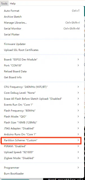
Set Partition Scheme to "Custom"
*QQ Music: Settings ->Lyrics ->Car Bluetooth Lyrics *NetEase Cloud Music: Settings - > General - > External Devices - > External Devices Bluetooth Lyrics
Operation Result
*Connect to Bluetooth from your phone or tablet. (Model: ESP32-Touch-LCD-3.5) *The song information is displayed on the screen.
