Working with Raspberry Pi
This deserializer board only supports the Raspberry Pi 5 mainboard and the Raspberry Pi Compute Module 5. The Compute Module 5 must be used with a carrier board that has a 22PIN MIPI-CSI interface.
Hardware Connection
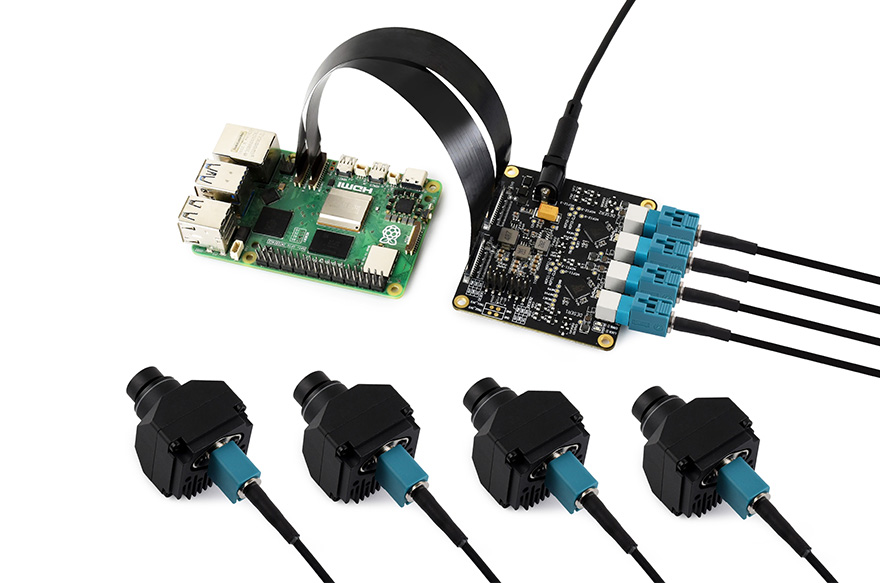
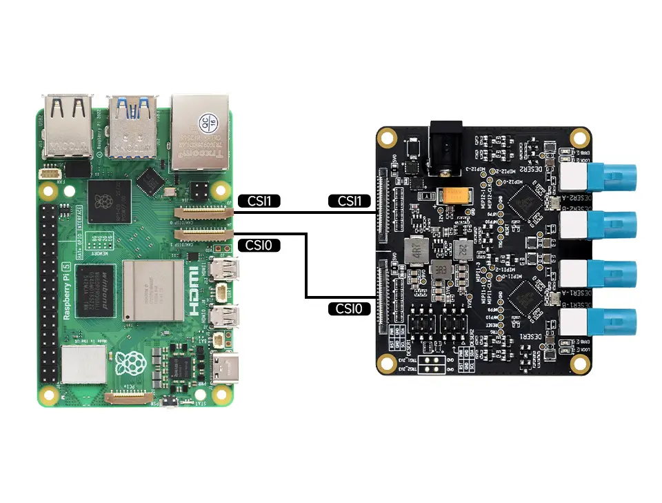
- Note: When connecting the devices, you must power both the deserializer board and the Raspberry Pi. To ensure correct power-up sequencing, first connect the power to the GMSL board, then connect the power to the Raspberry Pi and boot. Always power off before connecting or disconnecting camera cables.
Software Configuration
-
Tested using the official Raspberry Pi image
2024-07-04-raspios-bookworm-arm64.xz.- The download link for the corresponding version is provided here. You can click here to download the image package.
-
Flash the image file and boot the Raspberry Pi.
- Extract the
.imgimage file from the downloaded package. - Use the Raspberry Pi Imager or balenaEtcher to write the image file to a TF card.
- Insert the TF card with the flashed image into the Raspberry Pi mainboard, connect the hardware, and power on.
- Extract the
-
Open a terminal on the Raspberry Pi and use the following commands to download and extract the driver package:
wget https://files.waveshare.com/wiki/GMSL-Module-Board-4CH-A/gmsl-module-board-4ch-a.zipunzip gmsl-module-board-4ch-a.zip -
Install the drivers
-
Use the
cdcommand to enter the driver package directory:cd gmsl-module-board-4ch-a/ -
Copy the device tree file to
/boot/formware/overlays:sudo cp bin/6.6.31+rpt-rpi-2712/dtbo/max9296.dtbo /boot/firmware/overlays/ -
Copy the driver kernel module:
-
It is recommended to use the suggested system version.
sudo cp bin/6.6.31+rpt-rpi-2712/ko/max9296.ko /lib/modules/6.6.31+rpt-rpi-2712/
-
-
-
Configure the
/boot/firmware/config.txtfile-
Edit the file:
sudo nano /boot/firmware/config.txt -
Depending on which interface is used, add the appropriate setting lines to the end of the file.
dtoverlay=max9296,sensor-type=ISX031_MAX96717_2CHdtoverlay=max9296,cam0,sensor-type=ISX031_MAX96717_2CH#dtoverlay=max9296,sensor-type=ISX031_MAX96717_1CH#dtoverlay=max9296,cam0,sensor-type=ISX031_MAX96717_1CH -
In the configuration lines, the csi1 interface is used by default. If you connect the hardware using the csi0 interface, add the
cam0parameter.sensor-type=ISX031_MAX96717_2CHsets the camera type, where2CHmeans two cameras are connected, and1CHmeans one camera is connected. The example above shows connecting four ISX031 cameras.
-
-
After setting, save the file and reboot the system with
sudo reboot -
After rebooting, load the driver:
sudo depmodsudo modprobe max9296
Quick Test
-
Install gstreamer1.0 tools:
sudo apt install gstreamer1.0-tools -y -
Configure the CSI and CFE driver pipeline.
-
Set script execution permissions:
cd ~/gmsl-module-board-4ch-a/sudo chmod a+x script/* -
Configure the pipeline:
./script/aili_run_camera.sh all 1920 1536 2ch -
The pipeline configuration command is
./aili_run_camera.sh csi_channel width hight deserdes_channel, where:csi_channelspecifies which CSI interface to use.allmeans use both csi0 and csi1,csi0means use csi0,csi1means use csi1.widthandheightset the camera resolution.deserdes_channelsets the number of channels used.1chuses the LINKA channel by default,2chuses both channels.
-
-
Run the preview script to display the preview window:
./script/aili_review_camera.sh all 1920 1536 2ch- Note: The preview script must use the same parameters as the pipeline link configuration.
-
After the preview script runs successfully, a preview window will appear. When multiple windows preview simultaneously, they may overlap; you can manually drag the windows to view each one.