IPCBOX-CM5-A
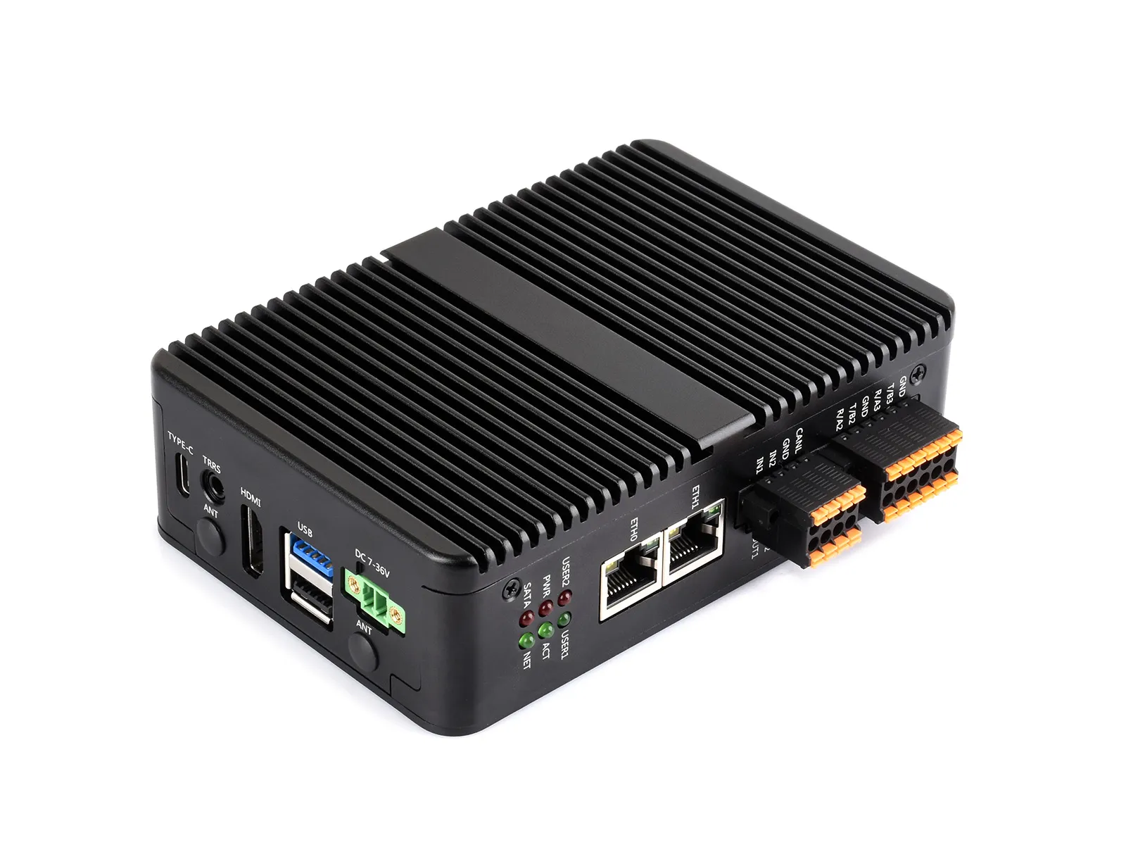
The IPCBOX-CM5-A is a carrier board designed for use with the Raspberry Pi Compute Module 5. It offers powerful features, including onboard 1x USB 3.2 Gen1, 3x USB 2.0, M.2 M KEY, M.2 B KEY (for 4G/5G modules), audio output interface, and dual Ethernet ports. Additionally, it provides RS485/RS232, CAN, digital inputs, and digital outputs via GPIO expansion for user convenience.
| SKU | Product |
|---|---|
| 34120 | IPCBOX-CM5-A (US) |
| 34121 | IPCBOX-CM5-A (EU) |
| 34122 | IPCBOX-CM5-A (UK) |
| 34123 | IPCBOX-CM5-B (US) |
| 34124 | IPCBOX-CM5-B (EU) |
| 34125 | IPCBOX-CM5-B (UK) |
Version Options
| Model | Image | Interface Specs |
|---|---|---|
| IPCBOX-CM5-A | 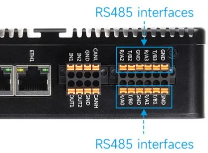 | Dual Ethernet ports, 4 × RS485 |
| IPCBOX-CM5-B | 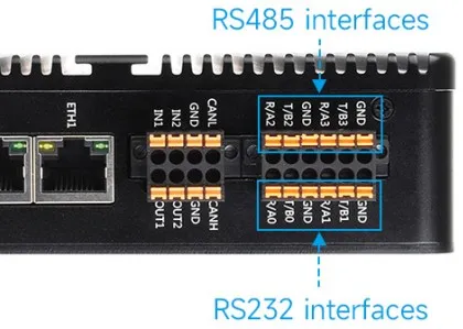 | Dual Ethernet ports, 2 × RS485 + 2 × RS232 |
Features
- Do not plug or unplug any devices other than USB and HDMI while the system is powered on
- The Type-C port can be used as a USB SLAVE interface for flashing images or powering the device
- Onboard 2 USB port groups, with a total maximum output current of 2A per group (1x USB 3.2 Gen1 + 3x USB 2.0 ports)
- Supports triple independent displays. When a MIPI DSI driver is added, the system will default to connecting to it regardless of whether a screen is connected, and the screen will display in split-screen mode (depending on the system version)
- Onboard M.2 M KEY interface, supports NVMe SSD protocol (or PCIe protocol AI modules)
- Onboard M.2 B KEY interface, supports 4G/5G communication modules
- Optional versions: 2x RS485 + 2x RS232, or 4x RS485 (isolated)
- 1x CAN supporting 1Mbps communication rate (isolated)
- 2x Digital Output + 2x Digital Input (isolated)
- 3.5mm headphone jack (supports microphone), PH2.0 speaker connector
- Single controllable buzzer
- Onboard EEPROM and encryption chip
- Onboard BOOT button: Press and hold the BOOT button before powering on, then connect to a PC via Type-C to enter flashing mode
- When using Type-C for flashing, do not connect other devices; otherwise, insufficient power may cause the device not to be recognized
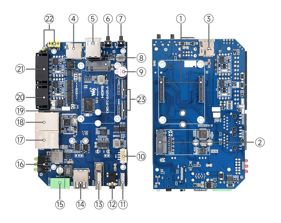
Onboard Resources
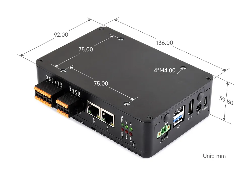
Dimensions
Development Related
Image Flashing
- Entering Download Mode
- Onboard BOOT Button: Press and hold the BOOT button before powering on, connect to PC via Type-C, and release the button after the power indicator lights up
- Flashing Images for LITE Versions: LITE Version Tutorial
- Flashing Images for EMMC Versions: EMMC Version Tutorial
NVMe(M.2 M KEY)
- The product supports all features in this tutorial: NVMe Usage Tutorial
- Includes: Formatting SSD | Partitioning SSD | Manual Mounting | Auto-mount on Boot | Read/Write Test
NVMe SSD Boot
- First, boot the Raspberry Pi using a TF card, mount and test the NVMe SSD to ensure the hardware functions correctly
- NVMe SSD Boot: Boot Configuration Tutorial
MIPI
The enclosure for this product does not have a cutout for this interface, so it cannot be accessed from inside the case. It can only be used when the enclosure is not assembled.
- You can add specific content to config.txt to select using DSI or CSI connection
- MIPI - DSI
- The product supports all features in this tutorial: DSI Interface Usage Tutorial
- DSI includes: DSI Interface Selection
- MIPI - CSI - The product supports all features in this tutorial: CSI Interface Usage Tutorial - CSI includes: CSI Interface Selection (Driver Settings) | Camera Detection | Displaying Real-time Preview | Taking a Photo | Recording a Video
Fan Control
- The product supports all features in this tutorial: Fan Usage Tutorial
- Includes: Manual Speed Control | View Current Speed | Restore Automatic Temperature Control
RTC
- With an RTC battery connected, the product supports all features in this tutorial: RTC Usage Tutorial
- Includes: Get RTC Time | Set RTC Time | Synchronize RTC Clock | Scheduled Shutdown | Scheduled Power-on - Low Power Wake-up | RTC Battery Charging
Audio Interface
When headphones are connected, the PH2.0 speaker interface will be muted, and the audio signal will be output through the headphone jack.
- The product features an onboard 3.5mm headphone jack and a PH2.0 4-pin speaker connector
- The product supports all features in this tutorial: USB Audio Function Usage Tutorial
- Includes: Query Audio Devices | Audio Recording | Audio Playback | Audio Input/Output Test
RS485/RS232
- The product features onboard RS485/RS232 interfaces (Version A does not have RS232)
- The product supports all features in this tutorial: RS485/RS232 Usage Tutorial
CAN
- The product has an onboard CAN interface (supports up to 1Mbps).
- The product supports all features in this tutorial: CAN Usage Guide
Digital Input Interface
The maximum input voltage supported by the product's digital input interface is 36V.
| Control Pin | Function | Description |
|---|---|---|
| GPIO23 | IN1 | Digital Input Channel 1 |
| GPIO24 | IN2 | Digital Input Channel 2 |
- When the digital input is high (above 2V), the GPIO reads as low
- When the digital input is low (below 0.9V), the GPIO reads as high
Digital Output Interface
The product's digital output is open-drain, with a maximum cut-off voltage of 150V and a maximum current of 500mA (on-resistance is 18Ω). Overvoltage or overcurrent will damage the device.
| Control Pin | Function | Description |
|---|---|---|
| GPIO27 | OUT1 | Digital Output Channel 1 |
| GPIO22 | OUT2 | Digital Output Channel 2 |
- When the GPIO outputs high, the digital output level is low
- When the GPIO outputs low, the digital output level is high-impedance
4G/5G
- The product has an onboard M.2 M KEY interface, supporting 4G / 5G communication modules.
- The product supports all features in this tutorial: 4G / 5G Usage Guide
Encryption Chip (ATSHA204)
- I2C address of this product's encryption chip (ATSHA204): 0x64
- The default I2C used by this product's encryption chip (ATSHA204) is: I2C1 (SDA:GPIO2, SCL:GPIO3)
- The product supports all features in this tutorial: ATSHA204 Usage Tutorial
- Includes: Data Read/Write | Chip Configuration Area Description
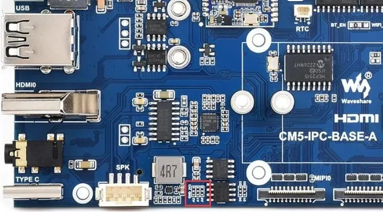
EEPROM (CAT24C32)
- I2C address of the chip: 0x50 (adjustable by changing the soldering position of resistors A0~A2)
- The default I2C connection for the chip is: I2C1 (SDA:GPIO2, SCL:GPIO3) I2C1 (SDA:GPIO2, SCL:GPIO3)
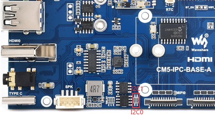
I2C Interface
- The default I2C bus used by the carrier board is I2C1 (SDA:GPIO2, SCL:GPIO3)
- This I2C interface is currently used for the onboard encryption chip (ATSHA204) and EEPROM (CAT24C32)
- It can be switched to use I2C0 by adjusting resistors
Buzzer
| Control Pin | Function | Description |
|---|---|---|
| GPIO7 | Buzzer | Active buzze |
- When the GPIO outputs high, the buzzer is silent.
- When the GPIO outputs low, the buzzer sounds.
LED Indicators
| LED Label | Function | Description |
|---|---|---|
| STAT | 4G/5G module enable LED | 4G/5G module interface LEDs |
| NET | 4G/5G module status LED | |
| PWR | Raspberry Pi system LEDs | Raspberry Pi system LEDs |
| ACT | Raspberry Pi activity LED | |
| USER1 | User-definable LED 1 | Connected to GPIO25, active low |
| USER2 | User-definable LED 2 | Connected to GPIO26, active low |