Assembly Steps
info
- Since the JETSON-ORIN-CASE-A and JETSON-ORIN-CASE-B differ only in the front and rear panel cutouts, we use the JETSON-ORIN-CASE-A as an example to demonstrate the assembly process.
- Please note that the front and rear panel cutouts on the B model are different from those on the A model.
- Before assembly, please check that all parts are present.
Components List
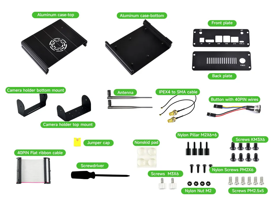
Among the parts, the screw kit includes:
- Jumper cap
- M3 screws
- M2 nylon pillars
- M2 nylon screws
- M2 nylon nuts
- M3 black flat-head screws
- M2.5 silver screws
Assembly Process
- Remove the plastic base from the Jetson Orin Nano/NX, and detach the PCB antenna from the wireless card to allow for future restoration during servicing or returns.
- Install the IPEX-4 adapter cable onto the front panel. To secure the SMA connector, first unscrew the retaining nut from the adapter cable, then fasten it on the outside of the front panel. Connect the other end of the adapter cable to the wireless card on the back.
- Secure the Jetson Orin Nano/NX board to the metal bottom cover using M2.5 silver screws, and at the same time fix the lower part of the front panel to the metal bottom cover with M3 black flat-head screws. When securing the board, you can determine the orientation by the camera connector position — the side of the case with the camera ribbon cable will have two elongated openings.
- Insert the jumper cap onto the AUTO ON and DIS pins on the motherboard. Remove the retaining nut from the LED button, secure it to the rear panel, and connect the button's ribbon cable to the motherboard's PWR BTN/GND and LED pins respectively.
- Connect the red wire to LED+, black wire to LED-; the yellow and blue wires are for the button and are not polarity-sensitive.
- After connecting the button, secure the lower part of the rear panel to the metal bottom cover with M3 black flat-head screws.
- If you need to connect a camera, route the camera ribbon cable through the opening on the right and insert it into the camera connector, making sure the metal contacts face downward.
- Secure the camera holder bottom mount to the metal top cover using M2.5 silver screws.
- Use the provided nylon screw kit to attach the camera to the camera holder top mount.
- Place nylon pillars between the camera and the bracket to prevent short circuits.
- Do not use metal screws here, as they may short the camera and damage the device.
- Attach the camera holder top mount to the camera holder bottom mount and tighten them together with M3 screws. During use, you can loosen the screws to adjust the bracket angle.
- Install the metal top cover onto the bottom cover, paying attention to orientation, then secure the upper sides of the panels with M3 black flat-head screws. Connect the other end of the camera ribbon cable to the camera, and attach the rubber-antenna.
- Finally, attach the non-slip rubber pads to the bottom.
-39f488f97394bc49e82c14f61b4bf360.webp) Install antenna adapter cable Install antenna adapter cable | -475bd3da6e8f55295e880fa13473b87c.webp) Secure motherboard to case Secure motherboard to case | -7ec96cab18eb2ad3536e91721a5a6dde.webp) Install LED button Install LED button |
|---|
-1cf361804b6829851ebe326fce0754d2.webp) Install camera ribbon cable Install camera ribbon cable | -5420944129c79e89ad2b88de654afd76.webp) Install camera holder bottom mount Install camera holder bottom mount | -e6423366f1fa006c903a170e3f8dac0e.webp) Install camera Install camera |
|---|
-d811958d9d20b4950490a080816274f5.webp) Install camera holder top mount Install camera holder top mount | -51e1031829c54fd72eef6c34f76247e9.webp) Install metal top cover Install metal top cover | -d1398888b82286f50f086f9e968c65e3.webp) Attach non-slip pads Attach non-slip pads |
|---|