LED Matrix
This page serves as the main entry for the LED Matrix product category, introducing the product lineup, technical features, and selection guidelines for Waveshare's HUB75 RGB LED matrix panels. For specific models and usage instructions, please refer to the corresponding subpages.
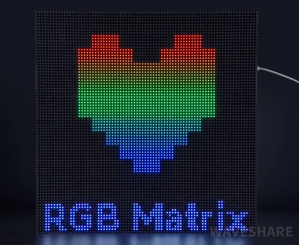
LED matrix panels (also known as RGB matrix or LED dot-matrix panels) use arrays of individually addressable RGB LEDs controlled via the HUB75 interface. They are widely used in information displays, scrolling signage, decorative lighting, art installations, and industrial status panels.
Product Lineup
| Model | Panel Resolution | Pixel Pitch | Viewing Angle | Supply Voltage / Current | Scan Mode | Panel Dimensions (mm) | Metal Frame (F) | GOB Coating (B) |
|---|---|---|---|---|---|---|---|---|
| RGB-Matrix-P2-64x64-B | 64×64 | 2mm | ≥140° | 5V / 3A | 1/32 scan | 128×128 | - | √ |
| RGB-Matrix-P2-64x64 | 64×64 | 2mm | ≥140° | 5V / 3A | 1/32 scan | 128×128 | - | - |
| RGB-Matrix-P2.5-64x32-B | 64×32 | 2.5mm | ≥140° | 5V / 2.5A | 1/16 scan | 160×80 | - | √ |
| RGB-Matrix-P2.5-64x32 | 64×32 | 2.5mm | ≥140° | 5V / 2.5A | 1/16 scan | 160×80 | - | - |
| RGB-Matrix-P2.5-64x64 | 64×64 | 2.5mm | ≥140° | 5V / 4A | 1/32 scan | 160×160 | - | - |
| RGB-Matrix-P2.5-96x48-F | 96×48 | 2.5mm | ≥140° | 5V / 4A | 1/24 scan | 240×120 | √ | - |
| RGB-Matrix-P3-64x32-B | 64×32 | 3mm | ≥160° | 5V / 2.5A | 1/16 scan | 192×96 | - | √ |
| RGB-Matrix-P3-64x32 | 64×32 | 3mm | ≥160° | 5V / 2.5A | 1/16 scan | 192×96 | - | - |
| RGB-Matrix-P3-64x64 | 64×64 | 3mm | ≥160° | 5V / 4A | 1/32 scan | 192×192 | - | - |
| RGB-Matrix-P3-64x64-F | 64×64 | 3mm | ≥140° | 5V / 4A | 1/32 scan | 192×192 | √ | - |
| RGB-Matrix-P4-64x32 | 64×32 | 4mm | ≥160° | 5V / 4A | 1/16 scan | 256×128 | - | - |
| RGB-Matrix-P4-80x40 | 80×40 | 4mm | ≥140° | 5V / 4A | 1/20 scan | 320×160 | - | - |
| RGB-Matrix-P5-64x32 | 64×32 | 5mm | ≥140° | 5V / 4A | 1/16 scan | 320×160 | - | - |
GOB (Glue On Board) process description: A transparent protective layer is applied over the LED beads, providing water resistance, dust resistance, impact resistance, and ESD protection. This makes GOB panels suitable for applications requiring frequent touching or use in humid environments. GOB does not change the resolution, pixel pitch, or control interface — only the surface protection is added.
Selection Guide
| Pixel Pitch | Key Features | Typical Applications | Platforms |
|---|---|---|---|
| P2.5 | Fine detail at close range, optional GOB protection | Indoor close-range information display, art installations, fine text/graphics | Arduino, ESP32, Raspberry Pi, STM32 |
| P3 | Balanced clarity and cost, comfortable viewing | Desktop/wall-mounted displays, environmental monitoring, scrolling text | Arduino, ESP32, Raspberry Pi, STM32 |
| P4 | Longer viewing distance, high fault tolerance, easy installation | Corridor/lobby information boards, floor indicators, public signage | Arduino, ESP32, Raspberry Pi, STM32 |
| P5 | Good readability at long distances, cost-effective | Indoor billboards, long-distance indicators, decorative displays | Arduino, ESP32, Raspberry Pi, STM32 |
Product Variants
- RGB Matrix Standard Series: High-density LED dot-matrix panels for information display and decorative lighting.
- RGB Matrix GOB Version Series: Features a GOB surface coating for water and moisture resistance. The panel can be cleaned with a damp cloth, and the coating reduces the impact of moisture and dust on LED solder joints, simplifying daily maintenance. The coating reduces the impact of moisture and dust on the LED solder joints.
Technical Features
- High Brightness: Suitable for a variety of ambient lighting conditions.
- Fast Response: Short response time, capable of high-frequency refresh without visible flicker.
- Environmentally Friendly: Contains no harmful substances like mercury, meeting environmental requirements.
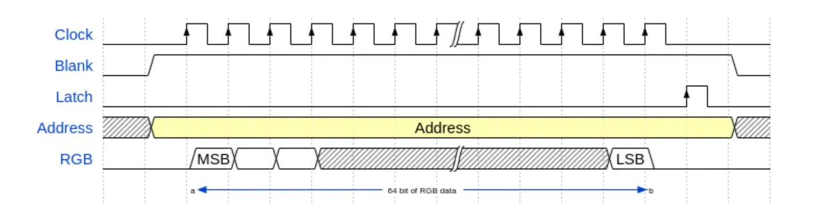
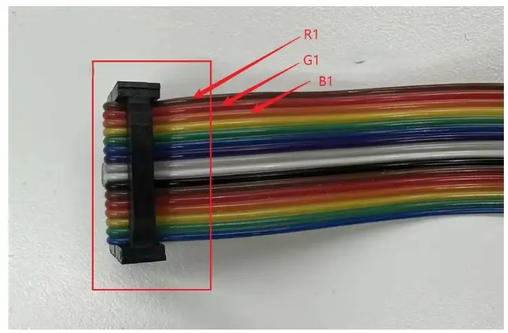
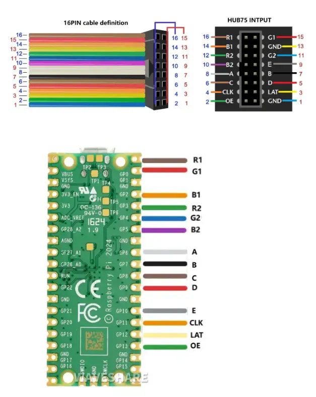
HUB75 Interface Description

- Use 5 address lines (A–E) to select the row to be displayed, choosing one row out of 32 (the E pin may be omitted if the panel height is 32 or fewer).
- Turn off the display by setting the Blank pin high; this prevents glitches or acts as blanking.
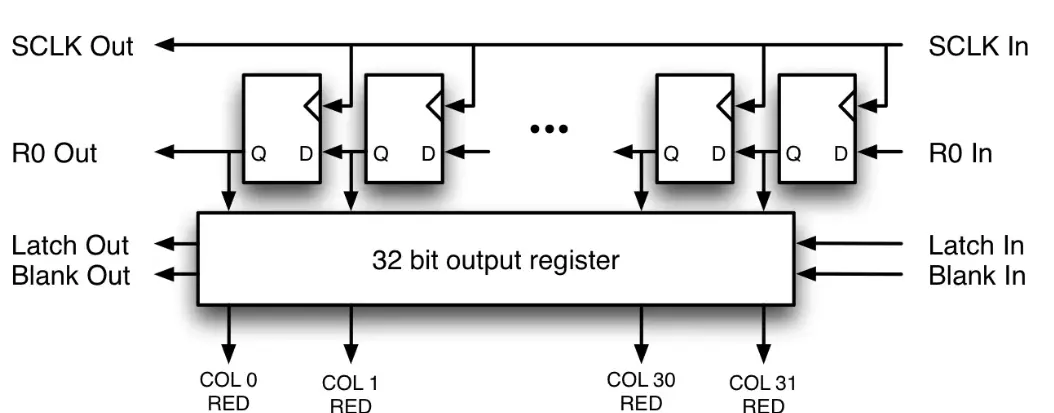
- Use the Clock pin and RGB pins to input data for the selected row.
- Toggle the Latch pin high -> low to load the data into the selected row.
- Turn on the display by pulling the Blank pin low.
The current example code uses a simple GPIO polling method for HUB75 control, which consumes significant MCU resources. In production, consider leveraging hardware peripherals (e.g., DMA, I2S parallel output, or dedicated LED drivers) to improve performance and reduce CPU load.
To summarize the operation flow: OE high (blank) → Set row address (A–E) → Shift RGB data column by column (R1–B2 + CLK) → Latch (LAT high → low) → OE low (display briefly) → OE high (blank) → Next row. When this loop runs fast enough, persistence of vision makes the entire panel appear continuously lit.
Basic Example Code (ESP-IDF)
hub75.c
#include "driver/gpio.h"
#include "rom/ets_sys.h"
#include "freertos/FreeRTOS.h"
#include "freertos/task.h"
#include "sdkconfig.h"
#include <stdint.h>

#define CONFIG_HUB75_PIN_R1 GPIO_NUM_4
#define CONFIG_HUB75_PIN_G1 GPIO_NUM_5
#define CONFIG_HUB75_PIN_B1 GPIO_NUM_6
#define CONFIG_HUB75_PIN_R2 GPIO_NUM_7
#define CONFIG_HUB75_PIN_G2 GPIO_NUM_15
#define CONFIG_HUB75_PIN_B2 GPIO_NUM_16
#define CONFIG_HUB75_PIN_A GPIO_NUM_18
#define CONFIG_HUB75_PIN_B GPIO_NUM_8
#define CONFIG_HUB75_PIN_C GPIO_NUM_3
#define CONFIG_HUB75_PIN_D GPIO_NUM_42
#define CONFIG_HUB75_PIN_E GPIO_NUM_9
#define CONFIG_HUB75_PIN_LAT GPIO_NUM_40
#define CONFIG_HUB75_PIN_OE GPIO_NUM_2
#define CONFIG_HUB75_PIN_CLK GPIO_NUM_41

#define HUB75_WIDTH 64
#define HUB75_HEIGHT 64
#define HUB75_HALF_ROWS  (HUB75_HEIGHT / 2)

/*
 * @brief Generate rising edge on HUB75 shift clock to shift current RGB parallel data into the panel shift register
 * @note Each call advances the data by one column position
 */
static inline void hub75_clk_pulse(void)
{
    gpio_set_level(CONFIG_HUB75_PIN_CLK,1);
    gpio_set_level(CONFIG_HUB75_PIN_CLK,0);
}

/*
 * @brief Trigger LAT latch to update the shift register contents to the output register
 * @note After latching and OE enabling, the current row data is actually lit
 */
static inline void hub75_latch(void)
{
    gpio_set_level(CONFIG_HUB75_PIN_LAT,1);
    gpio_set_level(CONFIG_HUB75_PIN_LAT,0);
}
/*
 * @brief Set row select address lines A~E
 * @param row Row address index (valid range depends on panel scan mode and HUB75_HALF_ROWS)
 * @note In this project, upper and lower halves output in parallel: the same row corresponds to one row in the upper half and one row in the lower half simultaneously
 */
static inline void hub75_set_row_address(uint32_t row)
{
    gpio_set_level(CONFIG_HUB75_PIN_A, (int)(row & 0x01U));
    gpio_set_level(CONFIG_HUB75_PIN_B, (int)((row >> 1U) & 0x01U));
    gpio_set_level(CONFIG_HUB75_PIN_C, (int)((row >> 2U) & 0x01U));
    gpio_set_level(CONFIG_HUB75_PIN_D, (int)((row >> 3U) & 0x01U));
    gpio_set_level(CONFIG_HUB75_PIN_E, (int)((row >> 4U) & 0x01U));
}

/*
 * @brief Push the upper/lower half RGB data for the current column and perform one shift
 * @param r1,g1,b1 RGB bits for the upper half at the current column (0/1)
 * @param r2,g2,b2 RGB bits for the lower half at the current column (0/1)
 * @note This function only sends "1 column of data"; to display a full row, it must be called HUB75_WIDTH times consecutively
 */
static inline void hub75_push_column(uint32_t r1, uint32_t g1, uint32_t b1, uint32_t r2, uint32_t g2, uint32_t b2)
{
    gpio_set_level(CONFIG_HUB75_PIN_R1, (int)r1);
    gpio_set_level(CONFIG_HUB75_PIN_G1, (int)g1);
    gpio_set_level(CONFIG_HUB75_PIN_B1, (int)b1);
    gpio_set_level(CONFIG_HUB75_PIN_R2, (int)r2);
    gpio_set_level(CONFIG_HUB75_PIN_G2, (int)g2);
    gpio_set_level(CONFIG_HUB75_PIN_B2, (int)b2);
    hub75_clk_pulse();
}

static void hub75_gpio_init(void)
{
    gpio_config_t io_conf = {
        .pin_bit_mask =
            (1ULL << CONFIG_HUB75_PIN_R1)  |
            (1ULL << CONFIG_HUB75_PIN_G1)  |
            (1ULL << CONFIG_HUB75_PIN_B1)  |
            (1ULL << CONFIG_HUB75_PIN_R2)  |
            (1ULL << CONFIG_HUB75_PIN_G2)  |
            (1ULL << CONFIG_HUB75_PIN_B2)  |
            (1ULL << CONFIG_HUB75_PIN_A)   |
            (1ULL << CONFIG_HUB75_PIN_B)   |
            (1ULL << CONFIG_HUB75_PIN_C)   |
            (1ULL << CONFIG_HUB75_PIN_D)   |
            (1ULL << CONFIG_HUB75_PIN_E)   |
            (1ULL << CONFIG_HUB75_PIN_LAT) |
            (1ULL << CONFIG_HUB75_PIN_OE)  |
            (1ULL << CONFIG_HUB75_PIN_CLK),
        .mode = GPIO_MODE_OUTPUT,
        .pull_up_en = GPIO_PULLUP_DISABLE,
        .pull_down_en = GPIO_PULLDOWN_DISABLE,
        .intr_type = GPIO_INTR_DISABLE
    };
    gpio_config(&io_conf);
    gpio_set_level(CONFIG_HUB75_PIN_CLK,0);
    gpio_set_level(CONFIG_HUB75_PIN_LAT,0);
    gpio_set_level(CONFIG_HUB75_PIN_OE,1);
}

void app_main(void)
{
    hub75_gpio_init();
    while (true) {
        uint32_t row = 0;
        while (row < HUB75_HALF_ROWS) {
            uint32_t col = 0;
            gpio_set_level(CONFIG_HUB75_PIN_OE,1);
            hub75_set_row_address(row);
            while (col < HUB75_WIDTH) {
                hub75_push_column(1, 0, 0, 1, 0, 0);
                col++;
            }
            hub75_latch();
            gpio_set_level(CONFIG_HUB75_PIN_OE,0);
            ets_delay_us(80);
            gpio_set_level(CONFIG_HUB75_PIN_OE,1);
            row++;
        }
        vTaskDelay(1);
    }
}
BCM Signal Control
The basic HUB75 drive above uses only 1-bit RGB data per channel, producing at most 8 colors (2³).
To achieve a wider color range, we use BCM (Binary Code Modulation) to control the display duration of each bit, enabling color mixing through time-domain weighting.
BCM splits each refresh cycle into multiple time slices with binary-weighted durations. Instead of fixed-duty-cycle PWM, each bit of a color value corresponds to a time slice whose length doubles with each higher bit — giving each bit proportional influence on perceived brightness.

Examples and Explanations
For example, set the total display time slice to 35 µs and use a 3-bit color depth. If the lowest bit time unit is 5 µs, the 3 bits can be assigned binary weights of 5 µs, 10 µs, and 20 µs, corresponding to a weight ratio of 1:2:4. Each color channel then has a range of 0–7 (binary 000–111).
Consider a pixel with color values R=7, G=2, B=0. In binary: R=111, G=010, B=000. During the 35 µs cycle, the R channel is lit for all three time slices (5+10+20 = 35 µs), the G channel is lit only during the 10 µs slice, and the B channel remains off. The result is a reddish-orange color. By adjusting the G channel value, you can mix R and G in different proportions to produce a range of intermediate colors.
Example Code
hub75-BCM.c
#define COLOR_R_LEVEL    7
#define COLOR_G_LEVEL    2
#define COLOR_B_LEVEL    0

#define COLOR_BITS       3 // Each color channel uses 3 bits for brightness (8 levels, 0–7)
#define ROW_ON_US        5 // BCM base time unit (microseconds)

/*
 * @brief Scan one row and push the current row's RGB data to the panel
 * @param row Row address index (valid range depends on panel scan mode and HUB75_HALF_ROWS)
 * @param r_on,g_on,b_on RGB bits for the upper half of the current row (0/1)
 * @param hold_us Display time for the current row when scanning (unit: microseconds)
 */
static inline void hub75_scan_one_row(uint32_t row, uint32_t r_on, uint32_t g_on, uint32_t b_on, uint32_t hold_us)
{
    uint32_t col = 0;
    hub75_set_row_address(row);
    while (col < HUB75_WIDTH) {
        hub75_push_column(r_on, g_on, b_on, r_on, g_on, b_on);
        col++;
    }
    hub75_latch();
    gpio_set_level(CONFIG_HUB75_PIN_OE,0);
    ets_delay_us(hold_us);
    gpio_set_level(CONFIG_HUB75_PIN_OE,1);
}

void app_main(void)
{
        uint32_t bit = 0;
        while (bit < COLOR_BITS) {
            const uint32_t r_on = (COLOR_R_LEVEL >> bit) & 0x01U;
            const uint32_t g_on = (COLOR_G_LEVEL >> bit) & 0x01U;
            const uint32_t b_on = (COLOR_B_LEVEL >> bit) & 0x01U;
            const uint32_t hold_us = (ROW_ON_US << bit);
            uint32_t row = 0;
            while (row < HUB75_HALF_ROWS) {
                hub75_scan_one_row(row, r_on, g_on, b_on, hold_us);
                row++;
            }
            bit++;
        }
}
Cascading Display
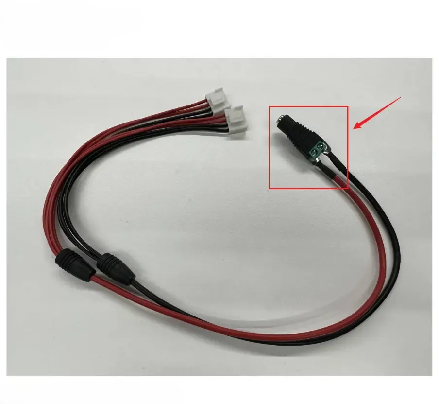
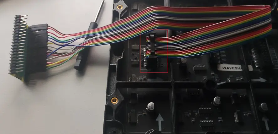
A single panel's display area is limited. To expand it, multiple panels can be daisy-chained using the HUB75 cascade interface.
Each panel provides both an input and an output connector. The output of one panel connects to the input of the next. All panels in the chain share the CLK, LAT, and OE control signals, while RGB data propagates through the chain stage by stage.
Since HUB75 data is shifted in serially via CLK, the first data shifted in is pushed to the farthest panel in the chain. After all pixel data for a row has been shifted in across all panels, a single LAT pulse latches the data, and OE controls the display. The essence of cascading is: shared control signals (CLK/LAT/OE) + extended data path = uniform driving of multiple panels.
Examples and Explanations
To cascade two 64×64 HUB75 panels, simply increase the total width in the code. In the example below, we shift 64 columns of green followed by 64 columns of red. Because data enters from the MCU side, the panel closer to the MCU displays red (shifted in last), and the farther panel displays green (shifted in first).
Example Code
hub75-Cascade.c
#define PANEL_COUNT 2
#define HUB75_TOTAL_WIDTH  (64 * PANEL_COUNT)

void app_main(void)
{
    hub75_gpio_init();
    while (true) {
        uint32_t row = 0;
        while (row < HUB75_HALF_ROWS) {
            uint32_t col = 0;
            gpio_set_level(CONFIG_HUB75_PIN_OE,1);
            hub75_set_row_address(row);
            while (col < HUB75_TOTAL_WIDTH) {
                if (col < HUB75_WIDTH) {
                    // 2nd panel (far)
                    hub75_push_column(0, 1, 0, 0, 1, 0); // green
                }else{
                    // 1st panel (close to MCU)
                    hub75_push_column(1, 0, 0, 1, 0, 0); // red
                }
                col++;
            }
            hub75_latch();
            gpio_set_level(CONFIG_HUB75_PIN_OE,0);
            ets_delay_us(80);
            gpio_set_level(CONFIG_HUB75_PIN_OE,1);
            row++;
        }
        vTaskDelay(1);
    }
}
Workflow
 |  |  |  |
|---|---|---|---|
 |  |  |  |