Working with Raspberry Pi
The deserializer board is physically designed for the Raspberry Pi form factor and can be used with the Raspberry Pi 5 mainboard via a ribbon cable connection.
Hardware Connection
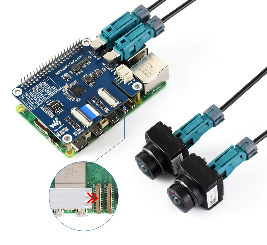
- Connect the CSI0 interface of the deserializer board to the CAM1 or CAM0 interface of the Raspberry Pi 5 using the supplied ribbon cable.
- Insert the deserializer board onto the 40PIN GPIO header of the Raspberry Pi 5.
- Connect the GMSL camera to the camera interface on the deserializer board using a coaxial cable.
- Set the CFG switch to the 0100 position (default configuration for the ISX031 camera).
Software Configuration
-
Flash the image file and boot the Raspberry Pi.
- Extract the
.imgimage file from the downloaded package. - Use the Raspberry Pi Imager or balenaEtcher to write the image file to a TF card.
- Insert the TF card with the flashed image into the Raspberry Pi mainboard, connect the hardware, and power on.
- Extract the
-
Open a terminal on the Raspberry Pi and use the following commands to download and extract the driver package:
wget https://files.waveshare.com/wiki/MAX9296-GMSL-Deser-Module/ws-rpi5-gmsl.zipunzip ws-rpi5-gmsl.zip -
Install the drivers
-
Use the
cdcommand to enter the driver package directory:cd ws-rpi5-gmsl/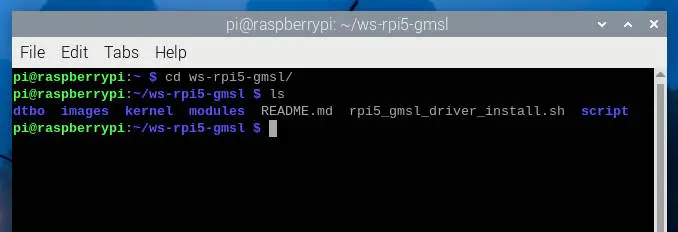
-
Add executable permissions to the installation script and execute it:
sudo chmod a+x rpi5_gmsl_driver_install.shsudo ./rpi5_gmsl_driver_install.sh
-
-
Configure the
config.txtfile-
Edit the file and add the dtoverlay setting as shown in the image below
sudo nano /boot/firmware/config.txt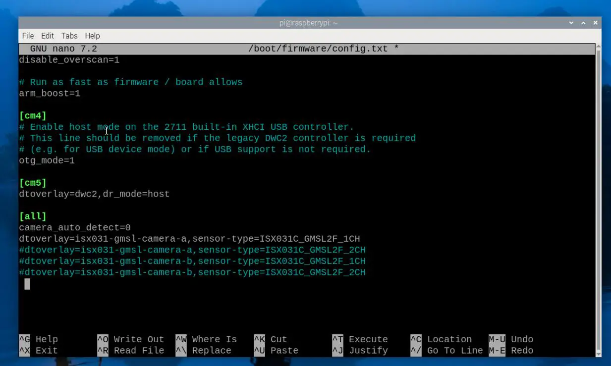
-
Depending on the connected camera, remove the comment symbol
#from the corresponding configuration line. Hereisx031-gmsl-camera-ais the camera model being connected, andsensor-type=ISX031C_GMSL2F_1CHsets the camera channel parameter. -
Table of camera models and corresponding configuration parameters:
Camera Model Camera Model Parameter Camera Channel Parameter Preview Parameter ISX031C-GMSL-Camera-H100 isx031-gmsl-camera-a ISX031C_GMSL2F_xCH ISX031-GMSL-Camera-A ISX031-GMSL-Camera-H60 isx031-gmsl-camera-b ISX031C_GMSL2F_xCH ISX031-GMSL-Camera-B ISX031-GMSL-Camera-H100 isx031-gmsl-camera-b ISX031C_GMSL2F_xCH ISX031-GMSL-Camera-B ISX031-GMSL-Camera-H120 isx031-gmsl-camera-b ISX031C_GMSL2F_xCH ISX031-GMSL-Camera-B ISX031-GMSL-Camera-H190 isx031-gmsl-camera-b ISX031C_GMSL2F_xCH ISX031-GMSL-Camera-B GMSL-2MP-Camera-A gmsl-2mp-camera-a GMSL_xCH GMSL-2MP-Camera-A GMSL-1MP-Camera-A gmsl-1mp-camera-a GMSL_1CH_LINKx / GMSL_2CH GMSL-1MP-Camera-A -
_xCH: can be configured as 1CH or 2CH depending on the connected camera. -
_LINKx: When using GMSL-1MP-Camera-A, the program cannot auto-detect the link; you need to specify it in the config file. For a single GMSL camera, specify the link based on the connected interface: GMSL0 usesGMSL_1CH_LINKA, GMSL1 usesGMSL_1CH_LINKB. For dual cameras, useGMSL_2CH.
-
-
-
If one ISX031 camera is connected (either link A or link B; the program will auto-detect):
dtoverlay=isx031-gmsl-camera-a,sensor-type=ISX031C_GMSL2F_1CH -
If two ISX031 cameras are connected:
dtoverlay=isx031-gmsl-camera-a,sensor-type=ISX031C_GMSL2F_2CH -
If connecting to the CAM0 interface, add the
cam0parameter at the end:dtoverlay=gmsl-isx031,sensor-type=ISX031C_GMSL2F_1CH,cam0dtoverlay=gmsl-isx031,sensor-type=ISX031C_GMSL2F_2CH,cam0 -
Supports separate configuration for CAM0 and CAM1 based on the camera model:
dtoverlay=gmsl-2mp-camera-a,sensor-type=GMSL_2CH,cam0dtoverlay=gmsl-1mp-camera-a,sensor-type=GMSL_2CH -
The default deserializer I2C address is
0x48(0x90 >> 1). To change it, add thedser-addrparameter:dtoverlay=isx031-gmsl-camera-a,sensor-type=ISX031C_GMSL2F_1CH,dser-addr=0x4adtoverlay=isx031-gmsl-camera-a,sensor-type=ISX031C_GMSL2F_2CH,dser-addr=0x4a -
After setting, save the file and reboot the system with
sudo reboot
Quick Test
-
Install gstreamer1.0 tools:
sudo apt install gstreamer1.0-tools -y -
The driver board provides a test script for preview. After rebooting the system, you can use the following commands to perform a preview test of the camera
-
Use the
-hparameter to view usage:ws_camera_preview.sh -h -
Connected to Raspberry Pi CAM1, 2x ISX031C:
ws_camera_preview.sh --csi1 ISX031-GMSL-Camera-A:2ch -
Connected to Raspberry Pi CAM1, 1x ISX031C:
ws_camera_preview.sh --csi1 ISX031-GMSL-Camera-A:1ch -
Connected to Raspberry Pi CAM0, 2x ISX031C:
ws_camera_preview.sh --csi0 ISX031-GMSL-Camera-A:2ch -
Connected to Raspberry Pi CAM0, 1x ISX031C:
ws_camera_preview.sh --csi0 ISX031-GMSL-Camera-A:1ch -
Preview both simultaneously:
ws_camera_preview.sh --csi0 GMSL-1MP-Camera-A:2ch --csi1 ISX031-GMSL-Camera-A:2ch
-
-
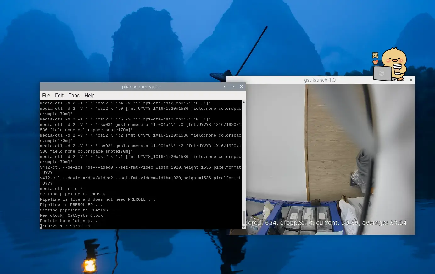
The following image is for reference only: