Modbus POE ETH IO 8CH
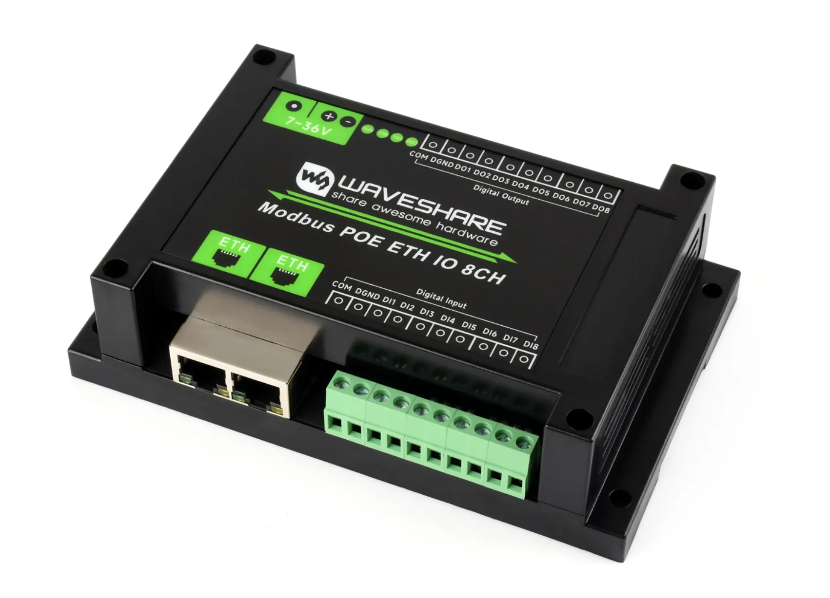
This product is an industrial-grade 8DI / 8DO isolated digital input/output module controlled via dual Ethernet interfaces. It supports both dry contact and wet contact inputs, utilizes Modbus RTU/Modbus TCP protocols, and features PoE (Power over Ethernet) capability. This relay module is very easy to use. Due to its fast communication, stability, reliability, and safety, it is an ideal choice for industrial control equipments and/or applications with high communication requirements.
| SKU | Product |
|---|---|
| 33917 | Modbus POE ETH IO 8CH |
Product Parameters
| Parameter | Specification |
|---|---|
| Supply Voltage | DC 7~36 V |
| Power Supply Methods | PoE Ethernet port, DC 5.5*2.1 power jack, or screw terminal (7 ~ 36 V) |
| Communication Interface | PoE Ethernet port, supporting IEEE 802.3af standard |
| Digital Input | 8DI, 5 ~ 36 V, dry contact/wet contact (NPN or PNP type), built-in bidirectional optocoupler |
| Digital Output | 8DO, 5 ~ 40 V, open-drain output, output load 500 mA/channel (MAX) |
| Modbus Protocol | Modbus RTU protocol or Modbus TCP protocol |
LED Indicator Descriptions
| LED Indicator | Status Description |
|---|---|
| RUN LED | Ethernet port running indicator. After the Ethernet port is working normally, it outputs a square wave with a period of 2 seconds |
| STA LED | MCU indicator. Flashes when the MCU is operating normally |
| TXD LED | Transmit indicator, lights up when transmitting data |
| RXD LED | Receive indicator, lights up when receiving data |
| Left Port Green LED | Illuminates when Ethernet port 1 is connected to an Ethernet network |
| Right Port Green LED | Illuminates when Ethernet port 2 is connected to an Ethernet network |
| Left Port Yellow LED | Illuminates when a TCP connection is established. Can be used to check if a communication link is established between the module and the host software |
| Right Port Yellow LED | Data activity LED. The state of this yellow LED changes when data is being transmitted over the Ethernet port, useful for determining if data transfer is occurring |
Basic Functions
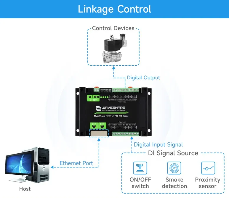
Supports reading switch inputs by sending Modbus RTU protocol commands via Ethernet, thereby controlling the digital outputs based on the input states
Wiring Instructions
Ethernet Port Wiring
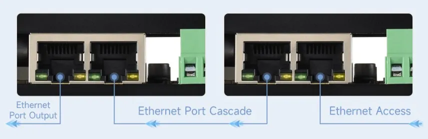
Connect the module to the local network using an Ethernet cable. Power the module via the 7~36V power terminal or via PoE. Both Ethernet ports have the same functionality and can be used for network communication and cascading.
Digital Input Wiring
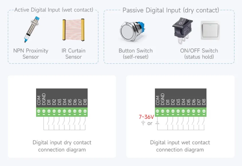
DI1-DI8 are the 8-channel signal input terminals. DGND is the common ground for the signal terminals. DICOM is the common terminal for input signals; it can be left floating, connected to the positive power supply, or connected to the negative power supply. Power can be drawn directly from the main supply or from an independent power source.
-
DICOM not connected (floating): Dry contact (passive) input

-
DICOM connected to positive power supply: Low-level trigger, NPN-type wet contact (active) input, voltage 5V-30V DC
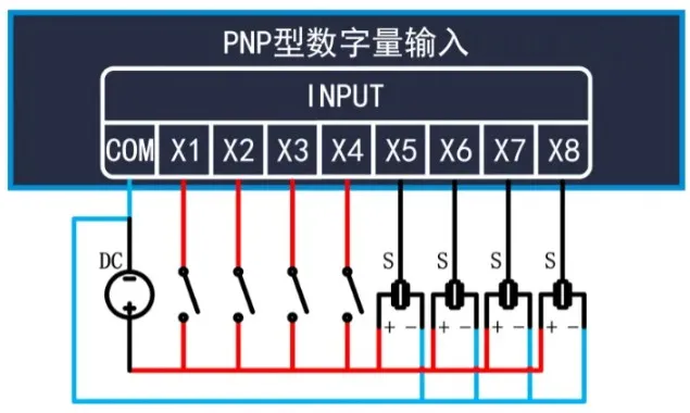
-
DICOM connected to negative power supply: High-level trigger, PNP-type wet contact (active) input
Digital Output Wiring
The output uses NPN Darlington transistors. DOCOM is the common terminal for the freewheeling diodes and should be connected to the positive terminal of the output power supply. The wiring diagram is as follows:
