Software Test
The demonstration introduces the operation methods of the following two software tools. The SSCOM serial port debugging assistant is more convenient to operate, requires no installation, and displays complete commands for easier analysis. The disadvantage is that the data is not intuitive. The Modbus Poll software operates directly on registers, making data observation more intuitive. Its disadvantage is that it does not display full commands, requiring familiarity with Modbus register operations.
You can choose either method for testing. It is recommended to use the SSCOM Serial Port Debug Assistant for the first test.
SSCOM Serial Port Debugging Assistant
-
Download SSCOM Serial Debugging Assistant and open it on your computer. Select the correct COM port, set baud rate to 9600, select HEX send and receive, enable Modbus CRC16 check, click "Multi_Strings" to open the send multi char window, and then click the corresponding function button to send the corresponding command.
- Turn on channel 1 relay
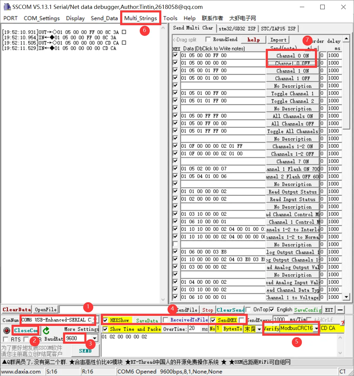
NoteThe module defaults to Normal mode upon delivery, and relays can be controlled directly via commands. If a command returns normally but the relay does not act, the module may have been switched to another control mode. You can check this by reading the Relay Control Mode command.
- Turn on channel 1 relay
-
To send other commands, select SendHEX, enable Modbus CRC16 check, enter the first six bytes of the command, and click Send. The software will automatically append the CRC code. For example, send the following command to set analog channel 1 to output 1 mA:
01 06 00 00 03 E8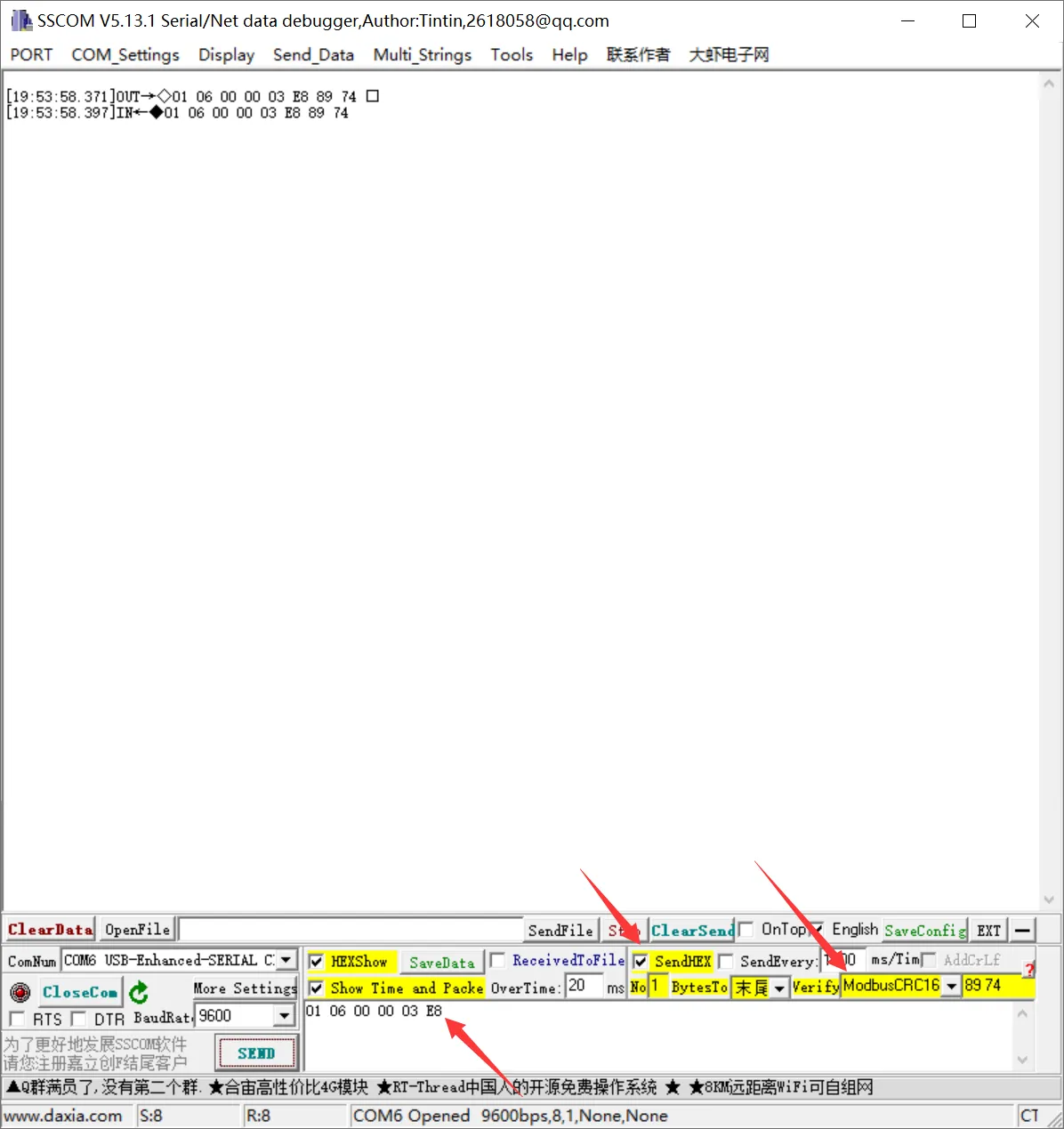
For more detailed control commands, please refer to the Development Protocol.
Modbus Poll Software
Relay Output
-
If the serial port software is inconvenient for observing data, you can choose the Modbus Poll software to read data. Download and install the Modbus Poll software.
-
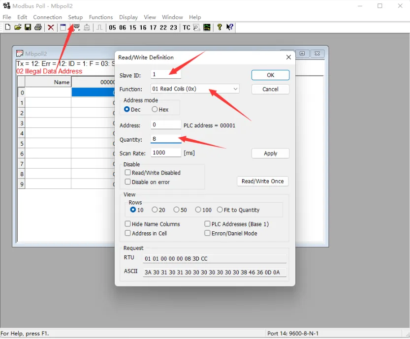
Open the software, select Setup -> Read/Write Definition. Set Slave ID to the actual device address, Function to 01 Read Coils, Quantity to 2 channels. Click OK to confirm.
-
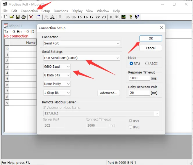
Select Connection->Connect..., choose the corresponding serial port, set the baud rate to 9600, and select 8 Data bits and None Parity. Click OK to connect.
-
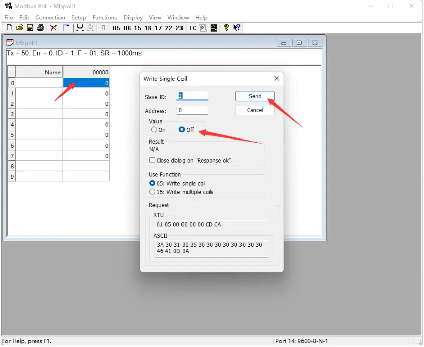
Once connected, you can view the current output channel status. Select the desired channel, double-click the status value to open the send dialog, choose On or Off, then click Send to control the relay.
Digital Input
-
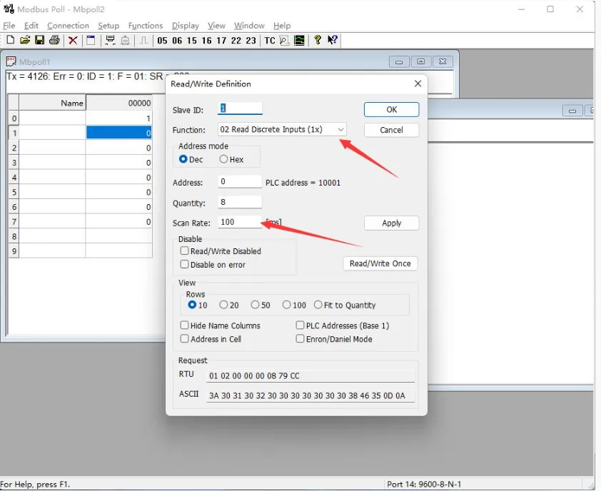
Select File -> New to create a new window. Select Setup -> Read/Write Definition. Set Slave ID to the actual device address, Function to 02 Read Discrete Inputs, Address to 0, Quantity to 2 channels, Scan Rate to 100 ms. Click OK to confirm.
-
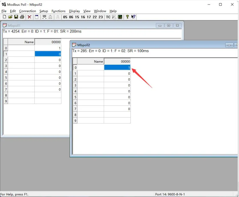
The newly created window 2 can display the current input status. Changing the input interface level will also change the corresponding value.
 Recommendation
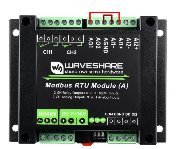
The following tests use AO1 and AI2 as examples. To achieve the same test results, complete the wiring first, then set the current output parameters. Do not enable current output before wiring is complete.
Current Output
-
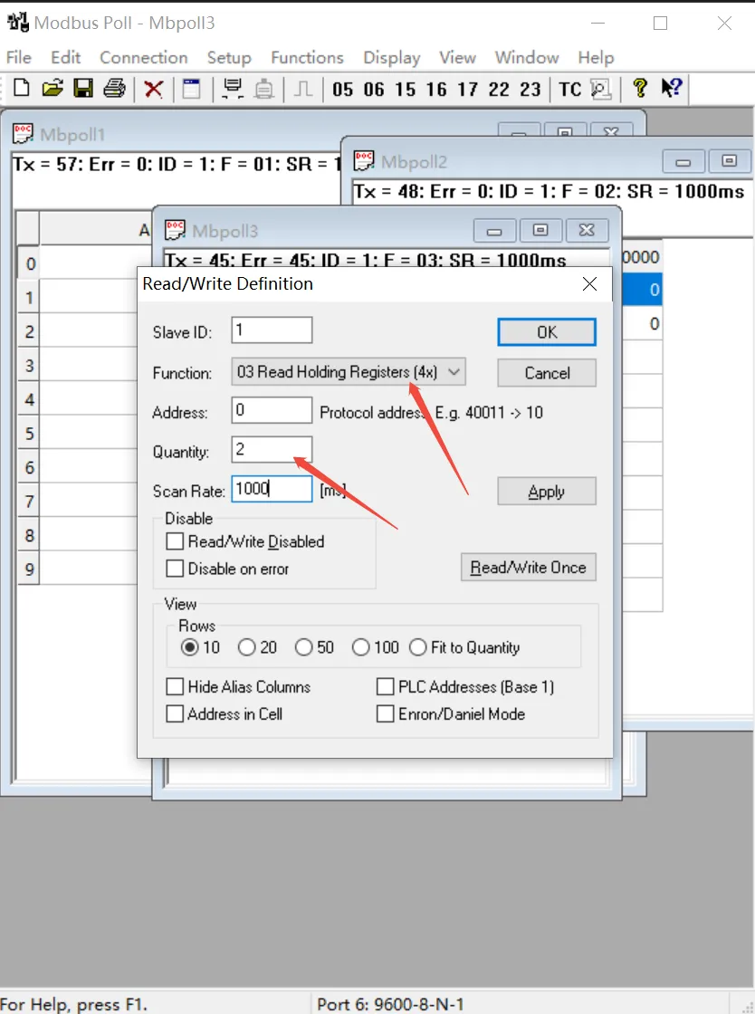
Select File -> New to create a new window. Select Setup -> Read/Write Definition. Set Slave ID to the actual device address, Function to 03 Read Holding Registers, Address to 0, Quantity to 2 channels, Scan Rate to 100 ms. Click OK to confirm.
-
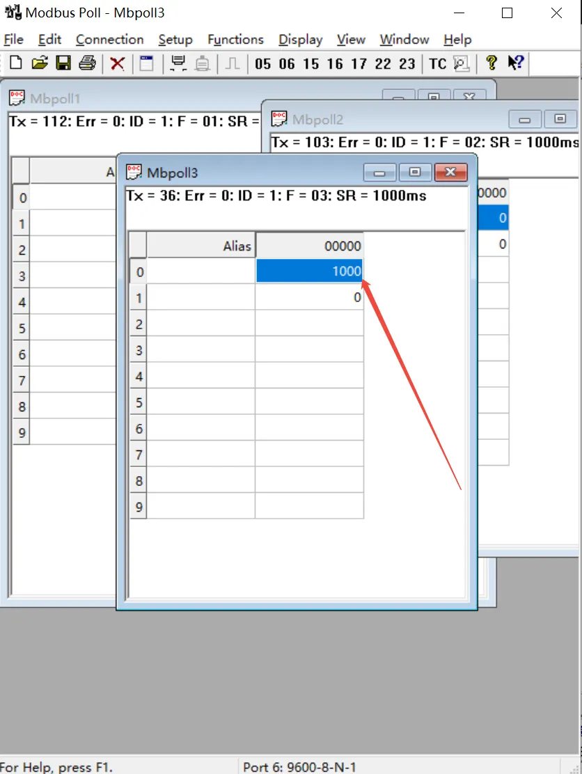
The new window (window 3) will display the register values for the current output channels. Adjusting the output current will change the corresponding register values.
Analog Input Channel Data Type
-
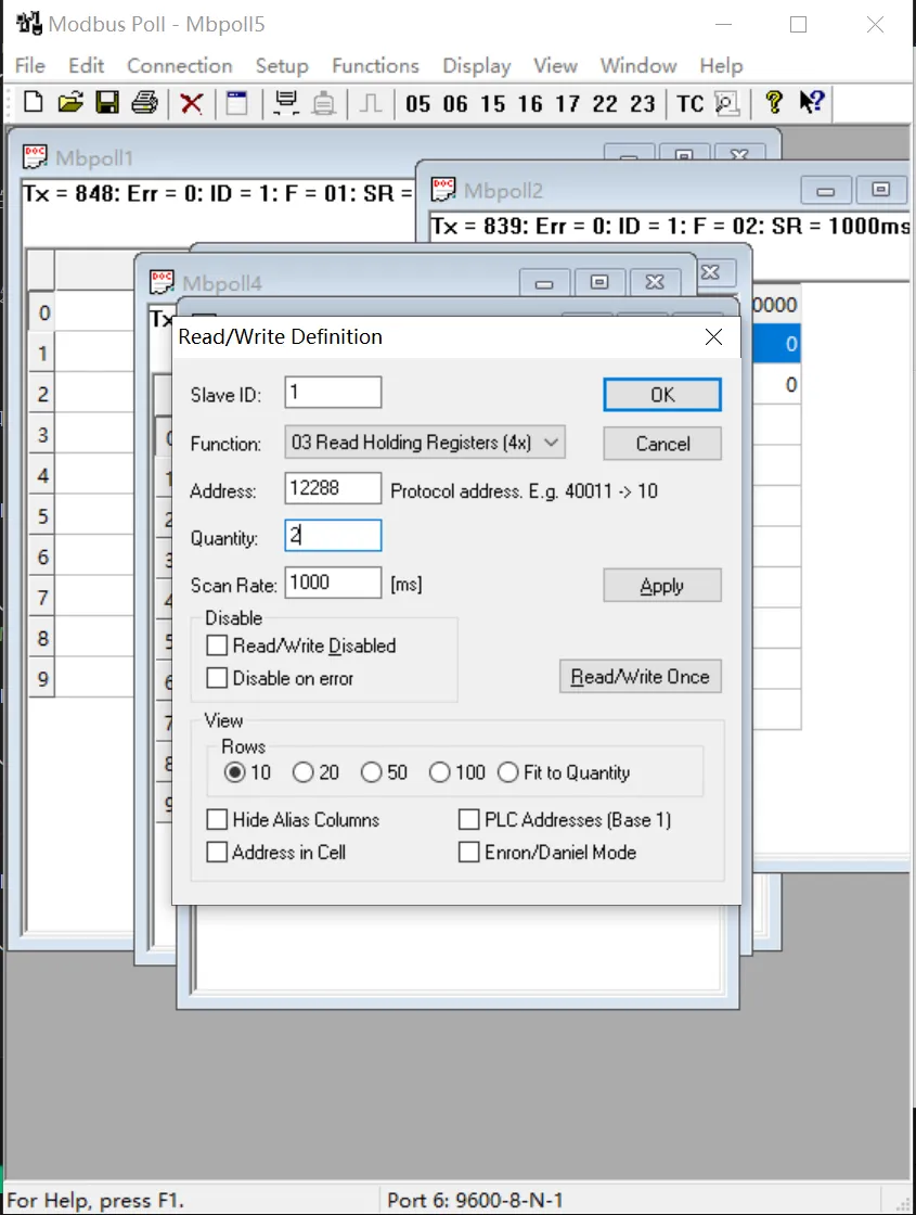
Select File -> New to create a new window. Select Setup -> Read/Write Definition. Set Slave ID to the actual device address, Function to 03 Read Holding Registers, Address to 12288, Quantity to 2 channels, Scan Rate to 100 ms. Click OK to confirm.
-
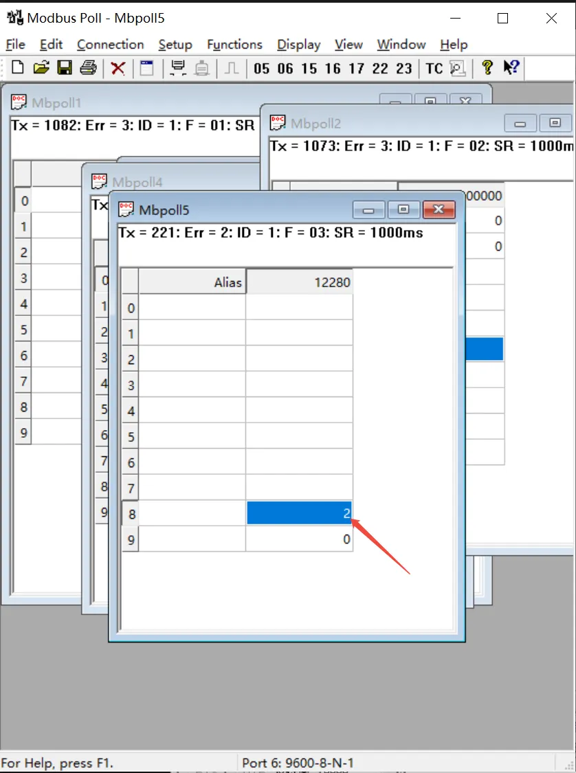
The new window (window 4) will display the data type of the analog input channels. After changing an analog input channel's data type to 02 (0 ~ 20 mA range), the corresponding register value will change.
Analog Input
-
Select File -> New to create a new window. Select Setup -> Read/Write Definition. Set Slave ID to the actual device address, Function to 04 Read Input Registers, Address to 0, Quantity to 2 channels, Scan Rate to 100 ms. Click OK to confirm.
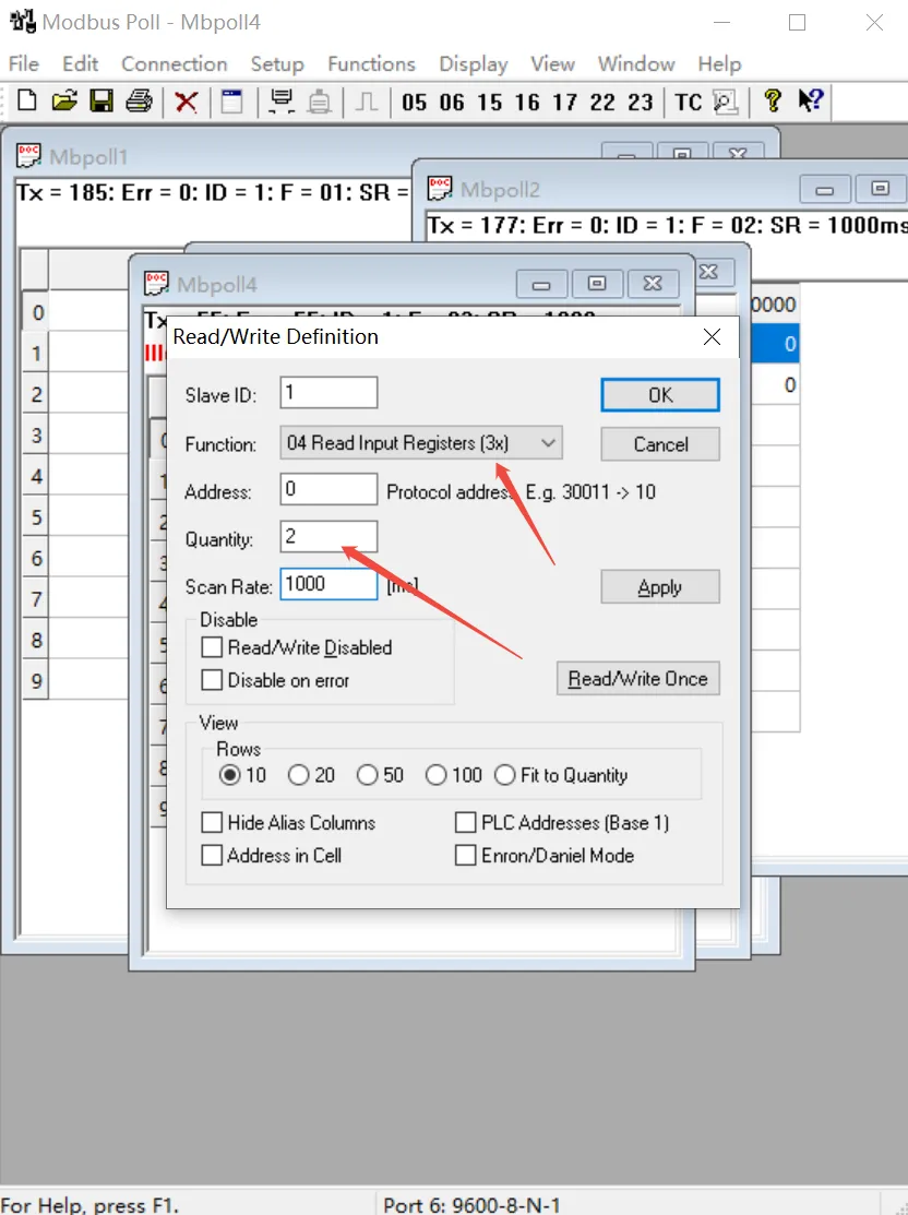
-
The new window (window 5) will display the sampled values of the analog input channels. Adjusting the output channel current will cause the input channel's measured current to change, and the corresponding register values will update accordingly.
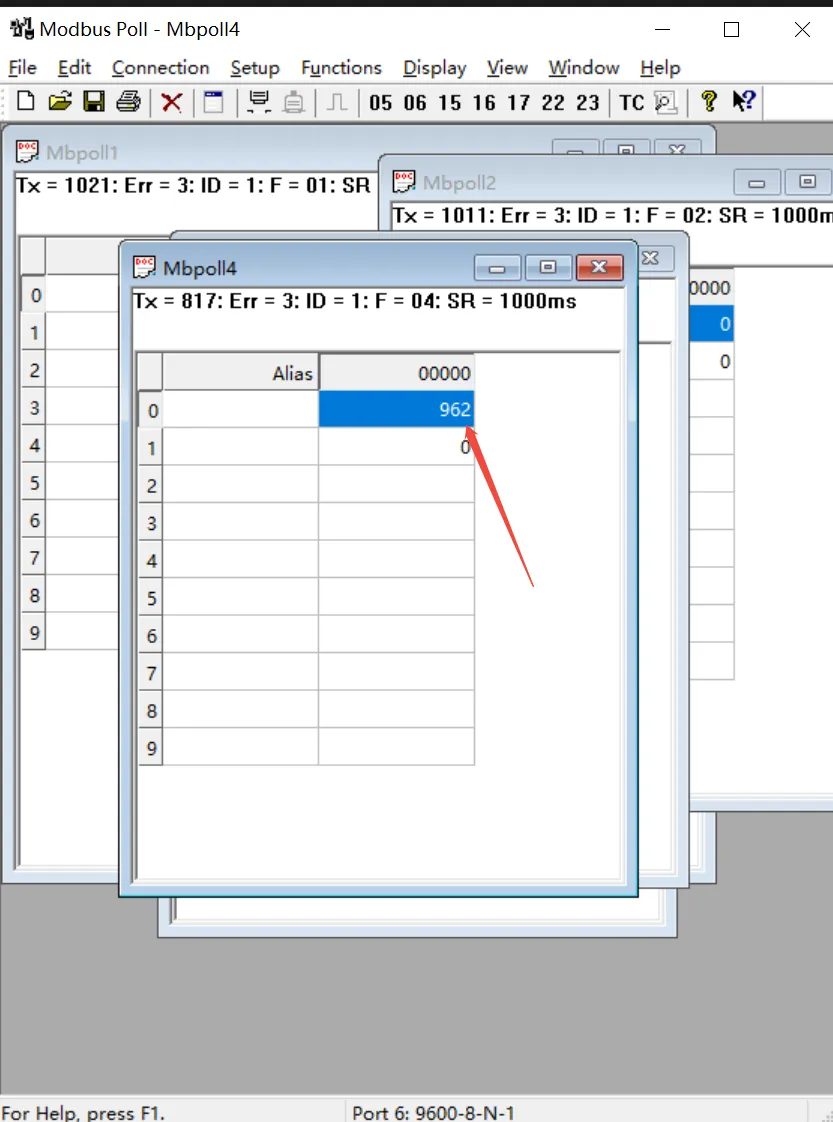
Result Explanation: Output channel accuracy is ±0.03 mA. Due to output cable loss and analog acquisition accuracy errors, the actual read register values may deviate slightly. Therefore, measurement results around 960 are within the normal range.