Modbus RTU PWM Input 8CH
| SKU | Product |
|---|---|
| 33919 | Modbus RTU PWM Input 8CH |
Hardware Description
Product Parameters
| Parameter | Specification |
|---|---|
| Communication Interface | RS485 |
| Communication Baud Rate | 4800, 9600, 19200, 38400, 57600, 115200, 128000, 256000 |
| Default Communication Format | 9600, N, 8, 1 |
| Modbus Protocol | Standard Modbus RTU Protocol |
| Supply Voltage | DC 7~36 V |
| Pulse Input Voltage Range | 3.3 V ~ 30 V |
| Pulse Frequency Measurement Range | 400 Hz ~ 50 kHz |
| Pulse Resolution | 0.01 Hz |
| Pulse Accuracy | 5‰ |
| Duty Cycle Measurement Range | 0 ~ 100 % |
| Duty Cycle Resolution | 0.01 % |
| Duty Cycle Accuracy | 5 ‰ |
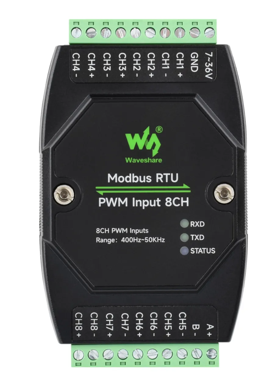
Indicator Light Description
| Indicator Light | Status Description |
|---|---|
| STATUS LED | MCU indicator, flashes when the MCU is operating normally |
| TXD LED | Transmission indicator, lights up when data is being sent |
| RXD LED | Reception indicator, lights up when data is being received |
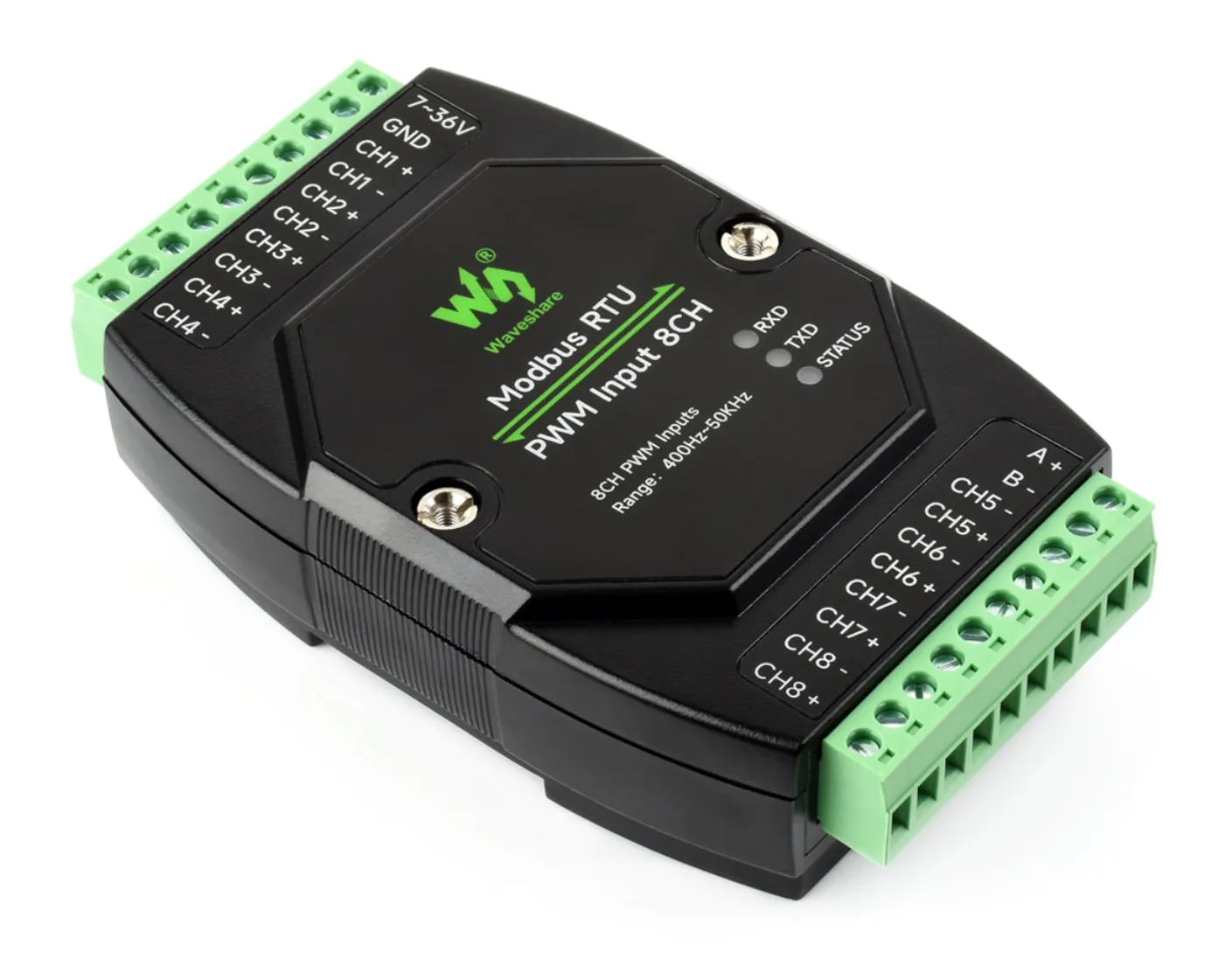
Hardware Description
CHN+ is the positive input, CHN- is the negative input. The PWM measurement frequency range is 400 Hz ~ 50 kHz, and the duty cycle range is 0 ~ 100%.
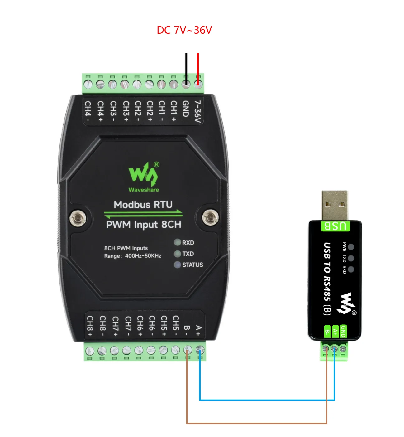
Hardware Connection Description
Connect the USB TO 485 converter to the target board using jumper wires, connecting A-->A and B-->B as shown in the figure below: